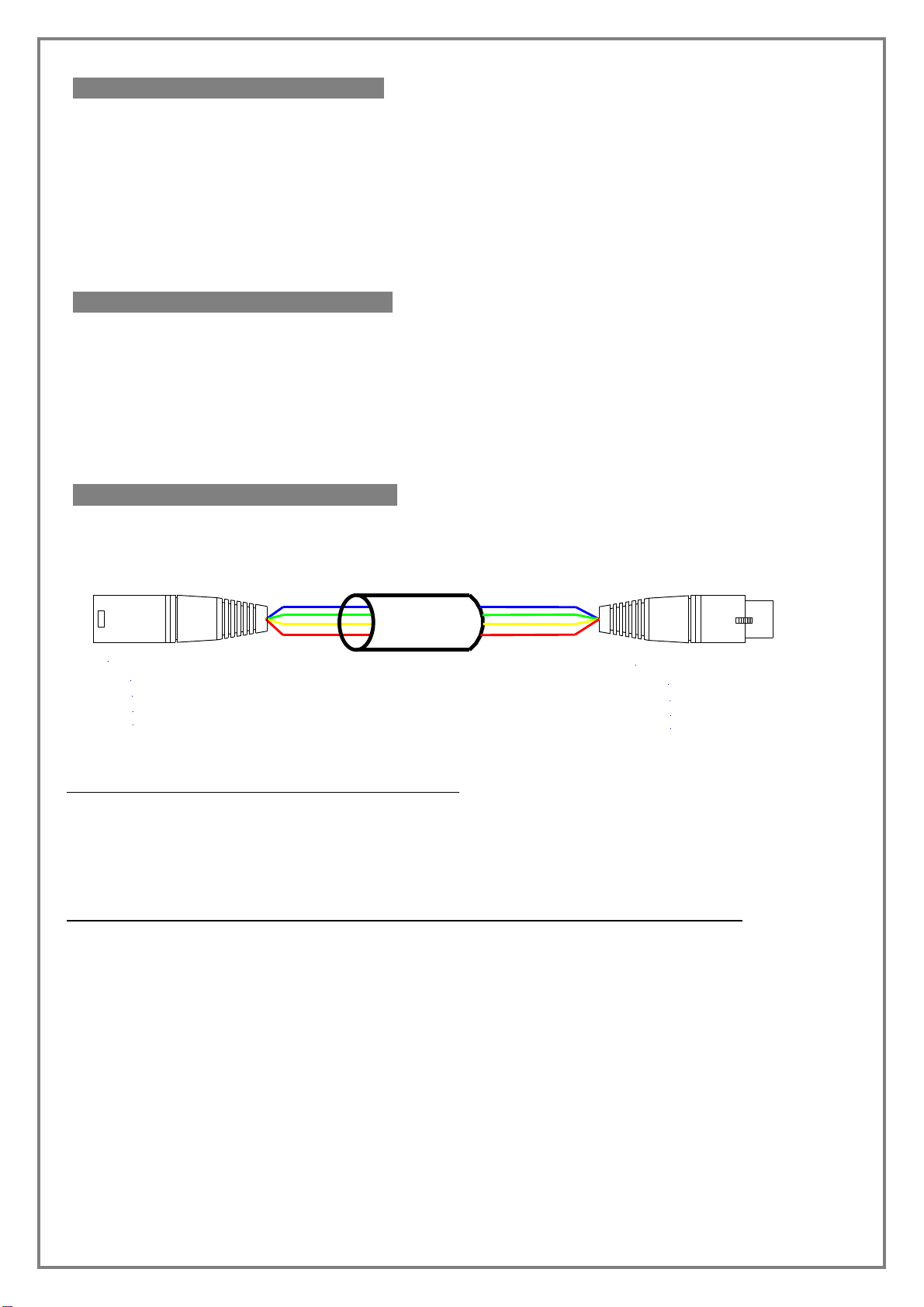
Cable Management
On the pan cover, under the camera plate are two M2.5 threaded holes. These can be used to
attach cable management clips.
Pan & Tilt Clutch Adjustment
Both the pan and the tilt clutches can be adjusted if needed.
To adjust the pan clutch, remove the Pan Cover which is
secured with a single screw. The cover will need to be
prized off as it is sealed with silicone sealant. The
Adjustment nut is on the top of the shaft and locked with
an M3 grub screw. Use a 1.5mm allen key to loosen the
locking screw and tighten the clutch adjustment nut until
to achieve the required clutch movement. It should be
set as lightly as possible without slipping. If it is
adjusted too tightly, damage may occur to the pan motor
gearbox.
Clean all the sealant from the cover and the body and re-apply a very thin layer of silicone
sealant before re-fitting the cover.
The tilt clutch adjuster is accessed by removing the Main Cover.
This has 3 screws. Take care not to damage the sealing
gasket. The Tilt Shaft Support Bearing may be on the shaft, as
in this picture, or may me retained in the main cover. Take care
not to lose this bearing.
The tilt adjustment is an M5 Nylock nut under the bearing on
the tilt shaft. You will need an 8mm spanner.
When re-fitting the cover ensure the gasket is located correctly
and that no wires become trapped between the body and the
cover.
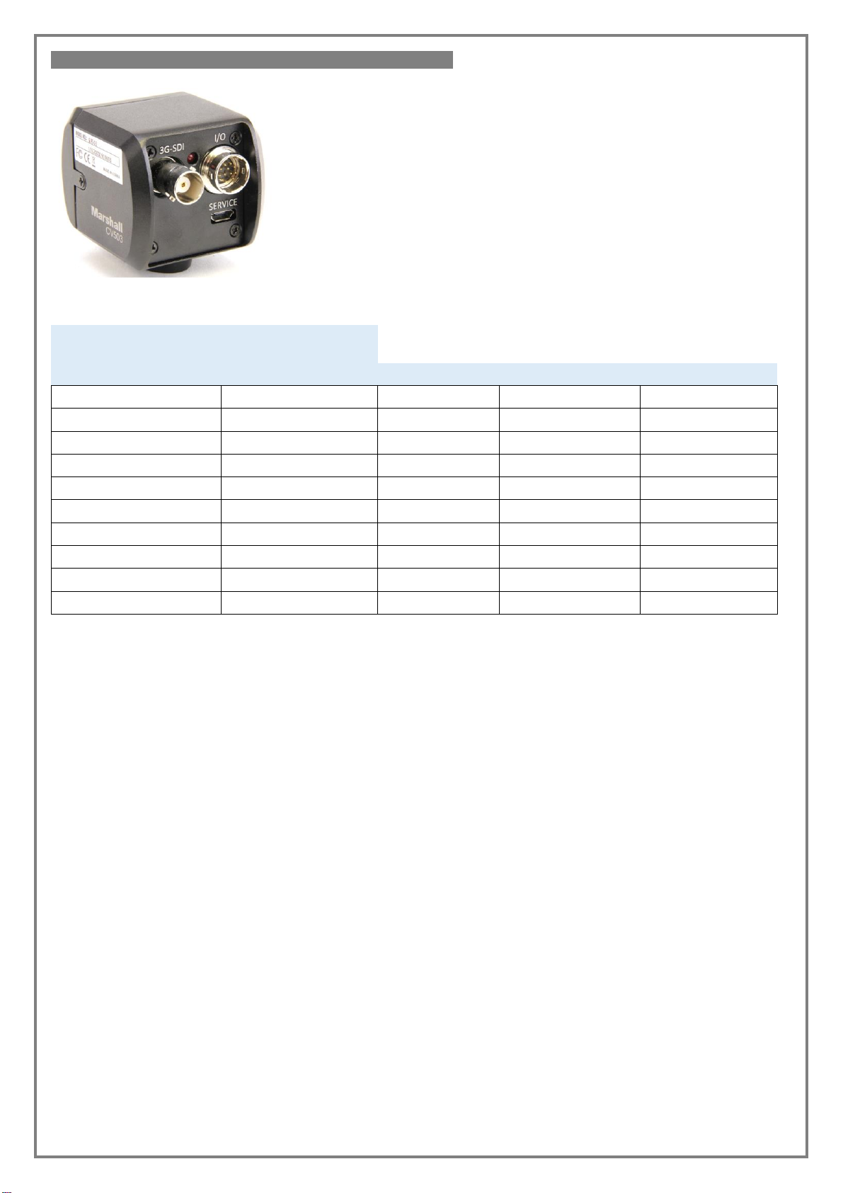
Specifications
Power: 12 –35v @ 0.5A + camera
Camera power: 12v @ 1A max.
Weight: 250gm.
Payload: 400gm.
20 –60mm wide
Cam Protocols: Marshall VISCA,
Dreamchip,
Pan Range: 350 deg.
Tilt Range: 360 deg.
Environmental: IP66 (with plugs)