2
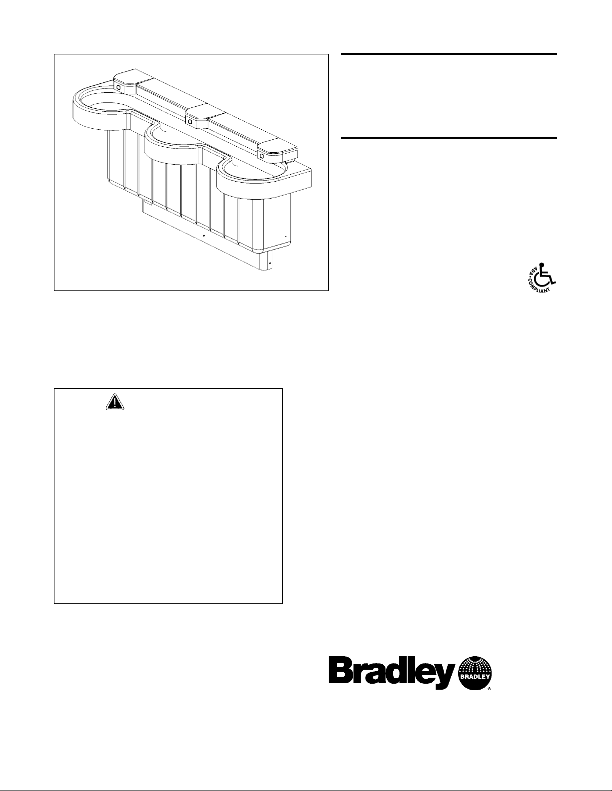
Express® Lavatory System SS-Series
SS-3/BIR/STD, SS-3/BIR/JUV Installation Instructions - For Service Only
5/11/04 Bradley Corporation • 215-1461 Rev. A; EN 03-813
Pre-Installation Information
Barrier-free and ADA compliant - standard height mounting
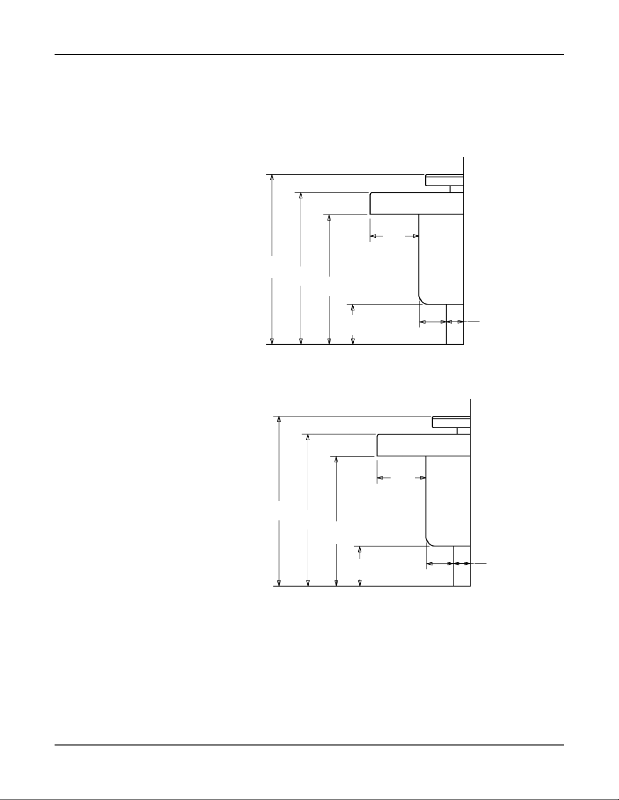
The SS-3/BIR/STD Express® Lavatory System must have a rim height of 34" above finished
floor to be compliant with Americans with Disabilities Act (ADA). When mounted at 34" rim
height, the Express® meets ADA, ANSI and UFAS requirements for barrier-free clearances,
reaches and controls. Always check local codes and ordinances for compliance.
Barrier-free and ADA compliant - juvenile height mounting
The SS-3/BIR/JUV Express® Lavatory System is compliant with Americans with Disabilities Act
(ADA) Accessibility Guidelines for Buildings and Facilities: Building Elements Designed for
Children's Use; Final Rule.
Infrared sensor and battery box
Each sprayhead is controlled by a separate sensor and and single-operation control box, enabling
each user to activate a single flow of water. Each valve uses less than half the maximum of hot
water allowed by the ANSI/ASHRAE/IESNA 90.1-1989-Standard.
Supplies required for installation:
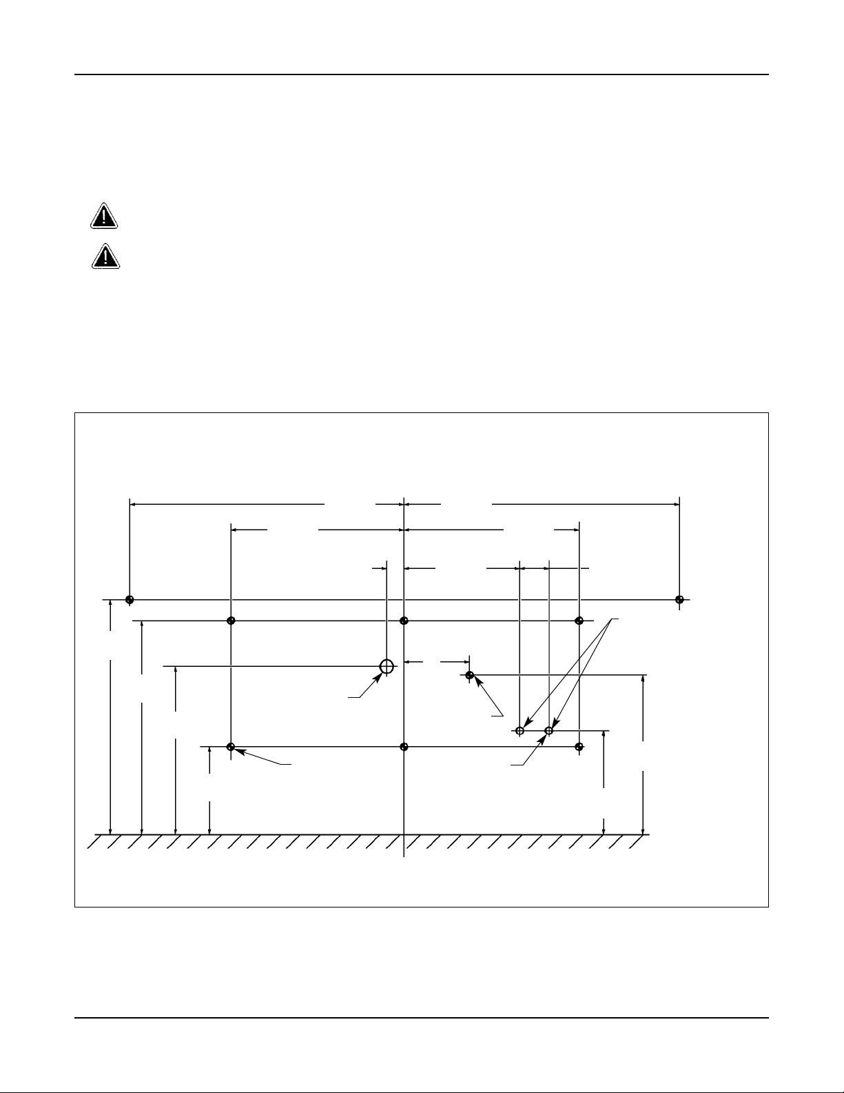
• (8) 3/8" wall anchors, bolts and washers to mount frame and bowl to wall
(minimum pull-out rating of 1,000 lbs.)
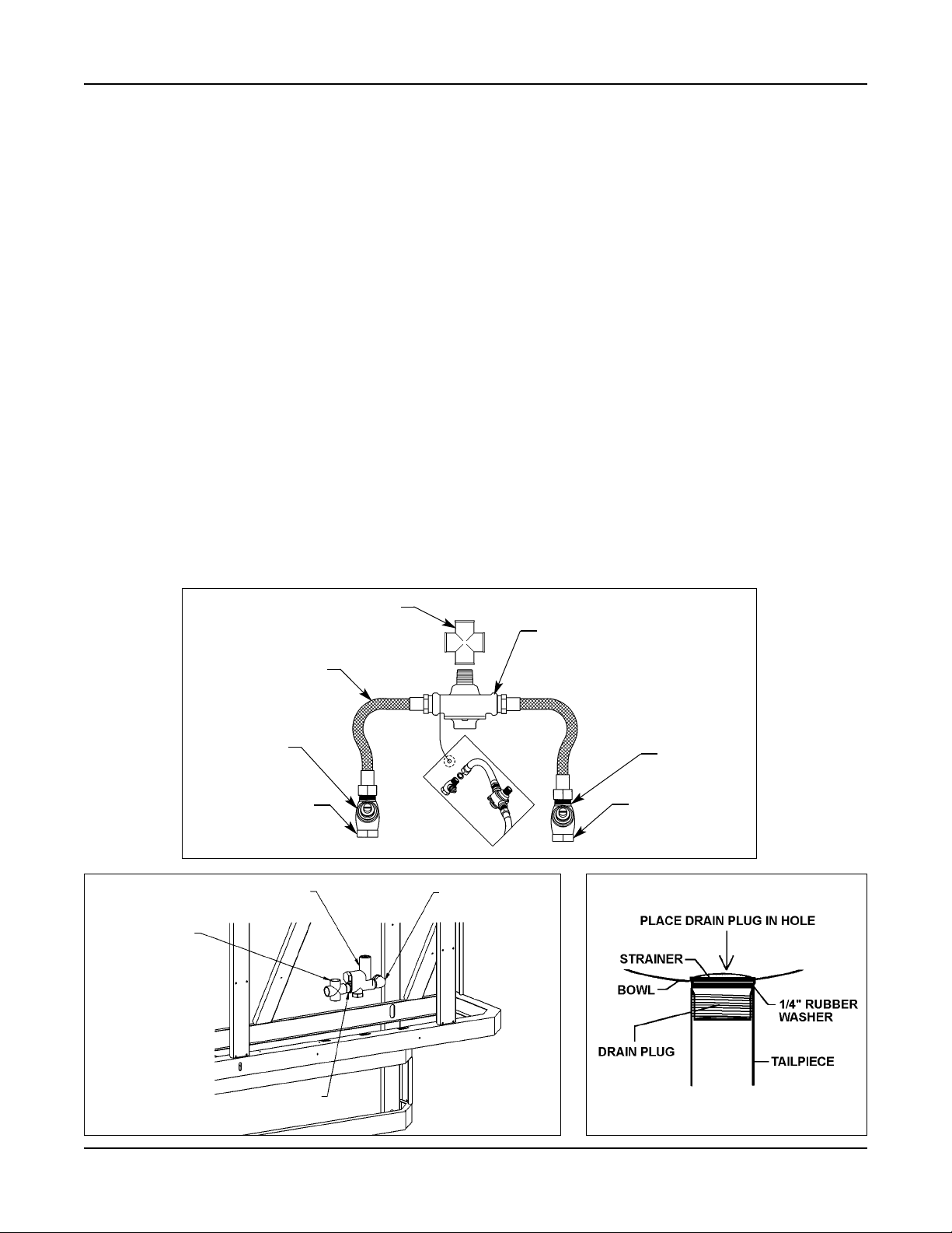
• 1/2" NPT tempered supply piping
• 1-1/2" NPT drain piping
• (18) “AA” alkaline batteries
• (1) 1/4" wall anchor, bolt and washer to mount center battery box to wall