SOFTLINK Sigfox WS868 User manual


Contents
1 Introduction 1
1.1 Sigfox communication network ....................................... 1
1.2 Module usage ................................................. 1
1.3 Hardware features .............................................. 1
2 Technical parameters overview 2
3 Configuration of the WS868-PLE2 module 3
3.1 Configuration of the module with using of optical converter ....................... 3
3.1.1 Installation of the ”WACO OptoConf” program .......................... 3
3.1.2 Connection of ”USB-IRDA” optical converter to computer .................... 4
3.1.3 Using of ”WACO OptoConf” program for configuration of modules ............... 4
3.1.4 General rules for configuration of the module by optical converter ............... 5
3.2 ”USB GateWay” and ”USB-IRDA” driver installation .......................... 6
3.2.1 How to disable driver signature enforcement in Windows 8 system ............... 8
3.2.2 How to disable driver signature enforcement in Windows 10 system ............... 8
3.2.3 Support of older OS Windows versions and OS Linux support .................. 8
3.3 Setting of parameters by using of optical ”USB-IRDA” converter .................... 9
3.3.1 Overview of module configuration parameters ........................... 10
3.4 Structure of module data messages ..................................... 12
4 Operational conditions 13
4.1 General Operation Risks ........................................... 13
4.1.1 Risk of mechanical and/or electric damage ............................. 13
4.1.2 Risk of premature battery discharge ................................ 13
4.2 The condition of modules on delivery .................................... 13
4.3 Modules storage ............................................... 13
4.4 Safety precautions .............................................. 14
4.5 Environmental protection and recycling .................................. 14
4.6 WS868-PLE2 module installation ...................................... 14
4.7 Module replacement and dismantling .................................... 15
4.8 Functional check of the module ....................................... 16
4.9 Operation of the WS868-PLE2 module ................................... 16
5 Troubleshooting 16
5.1 Possible causes of module failures ...................................... 16
5.1.1 Power supplying failures ....................................... 16
5.1.2 System failures ............................................ 17
5.1.3 Reading system failures ....................................... 17
5.1.4 Transmitter and receiver failures .................................. 17
5.2 Troubleshooting procedure .......................................... 18
6 Additional information 18
List of Tables
1 Overview of WS868-PLE2 module technical parameters ......................... 2
2 V´ypis vˇsech konfiguraˇcn´ıch parametr˚u modulu WS868-PLE2 ...................... 11
List of Figures
1 View of the WS868-PLE2 module ...................................... 2
2 Configuration of the module with using of optical converter ....................... 3
3 Displaying of the optical converter in the Windows’ ”Device Manager” ................. 4
4 Displaying of ”WACO OptoConf” configuration window” ........................ 5
5 List of variables in the working window of ”WACO OptoConf” program ................ 5
6 Example of module’s configuration table in the ”WACO OptoConf” window .............. 5
7 Displaying of the device without driver in ”Device Manager” window .................. 7
WS868-PLE2 i

8 Manual selection of the driver file from a folder .............................. 7
9 USB driver installation ............................................ 7
10 The WS868-PLE2 module configuration table ............................... 9
11 Detailed view of WS868-PLE2 module ................................... 14
12 Installation and setting of WS868-PLE2 module ............................. 15
WS868-PLE2 ii

1 Introduction
This document describes features, parameters and setting possibilities of the WS868-PLE2 module, which is used for
reading of Elster BK-G series gas-meters and for radio-broadcasting of the data from the gas-meter to the superior
remote reading system in form of Sigfox standard messages.
1.1 Sigfox communication network
Sigfox communication network is a global radio frequency (RF) communication system intended for collecting
data from the huge number of terminal devices that transmit only a very limited amount of data. This kind of
network services are commonly referred as ”Internet of Things” (”IoT”).
Sigfox technology (including communication protocol) is optimizing for maximum radio range, that enables
building of country wide RF networks with a maximum cost effectivity. Unification of technology, global register of
identification addresses as well as central registration and control system enable interconnection of national networks
(”roaming”) into one global Sigfox network.
The module is designed for using in free 868 MHz frequency band with maximum transmitting power of 25
mW that is commonly used in European countries. Maximum reach of Sigfox services in this band for devices
with maximum transmitting power in open terrain is in range of tens of kilometers. This extensive range is enabled
by using of ultra-low modulation frequency (Ultra Narrow Band Modulation) where communication sub-channel
bandwidth is just 100 - 600 bps (Baud). As the messages are transmitted with such extremely low speed, Sigfox
message was invented as short as possible with maximum length of 26 Byte (maximum data content of 12 Byte).
Optimized length of message has positive influence on the terminal device energy consumption during transmitting
and receiving.
Sigfox network supports also bi-directional communication, if ”Downlink” service for transfer of data in reverse
direction is allowed, in earmarked time interval the Sigfox base station can deliver to terminal device a special
downlink radio-message containing configuration commands.
National Sigfox RF network consists of number of base stations, that are connected by data channels into one central
node (”star” type topology). The messages from Sigfox RF network are transferred from Sigfox central network
server to the application servers of authorized users through the unified data interface via public Internet.
1.2 Module usage
The WS868-PLE2 module can be used for remote reading of Elster BK-G series residential gas-meters that are
equipped with special slot (”lock”) for external remote reading modules (e.g. IN-Z61) in the lower side of its
counter. The module is equipped with one magnetic sensor for registration of gas-meter counter revolution, one
mechanical contact for detection of detachment from gas-meter (”Tamper”) and one reset micro-switch (button) for
setting of internal counters to zero. The module continuously registers revolving of gas-meter pivotal wheel into its
internal counter and broadcasts info-messages with current status of gasmeter counter in form of Sigfox standard
radio-messages (hereinafter ”INFO-message”). The INFO-messages contain also service information about tamper
status, battery voltage and processor temperature.
The INFO-messages are transferred through the Sigfox network to the central network server (”Back-End”), from
which there are forwarded to assigned IP-address of their addressee through the Internet. The addressee of the
messages is an application server of remote reading service operator, where the messages are decoded and processed.
1.3 Hardware features
The module is enclosed in plastic casing designed for mounting directly to the BK-G series gas-meter counter slot
reserved for remote reading modules. The device is not suitable for using in exteriors without additional protection.
The module is power supplied by internal battery with up to 10 years lifetime for frequency of 4 - 6 broadcastings
per day. Battery lifetime can be negatively influenced by shorter broadcasting period, or by storing and operation
in sites with the temperatures exceeding the recommended range.
The module can be controlled and configured wirelessly - by infra-red remote control with using of optical converter.
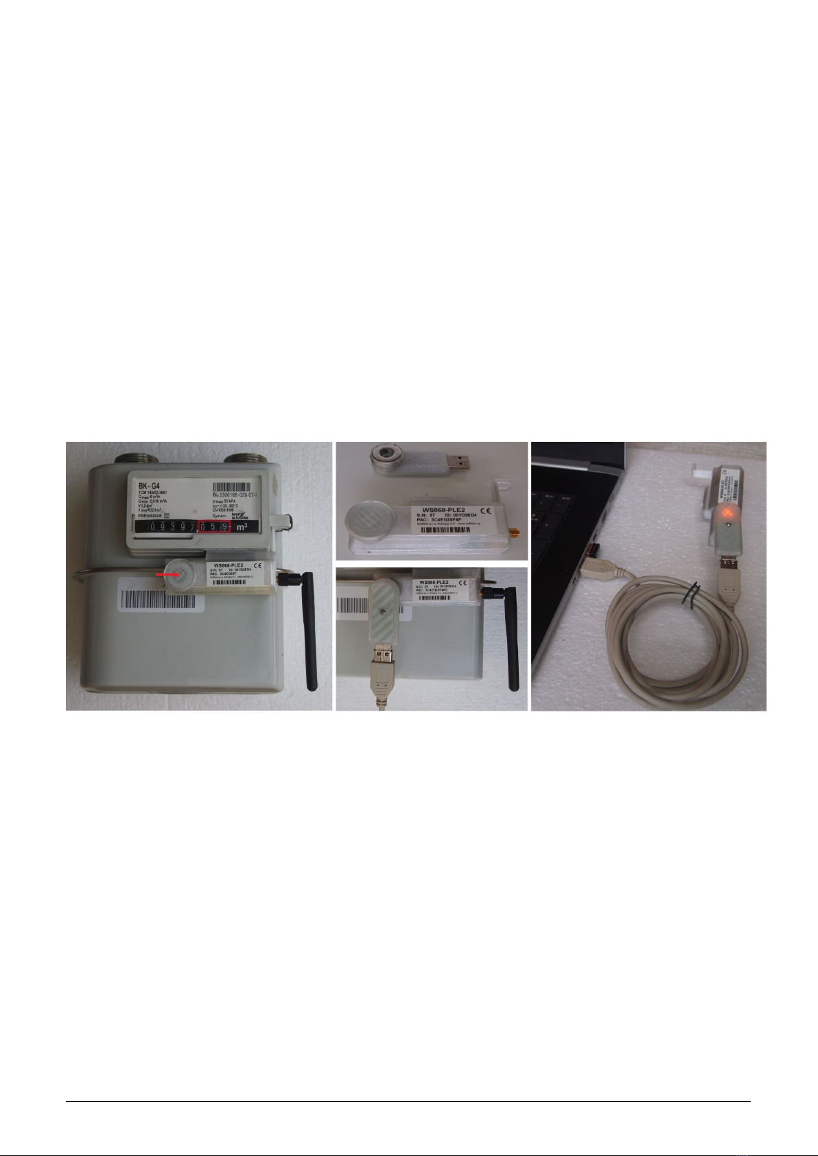
External appearance of the WS868-PLE2 module is shown in the figure 1. Position of infrared sensor for wireless
configuration is marked by green arrow.
WS868-PLE2 1
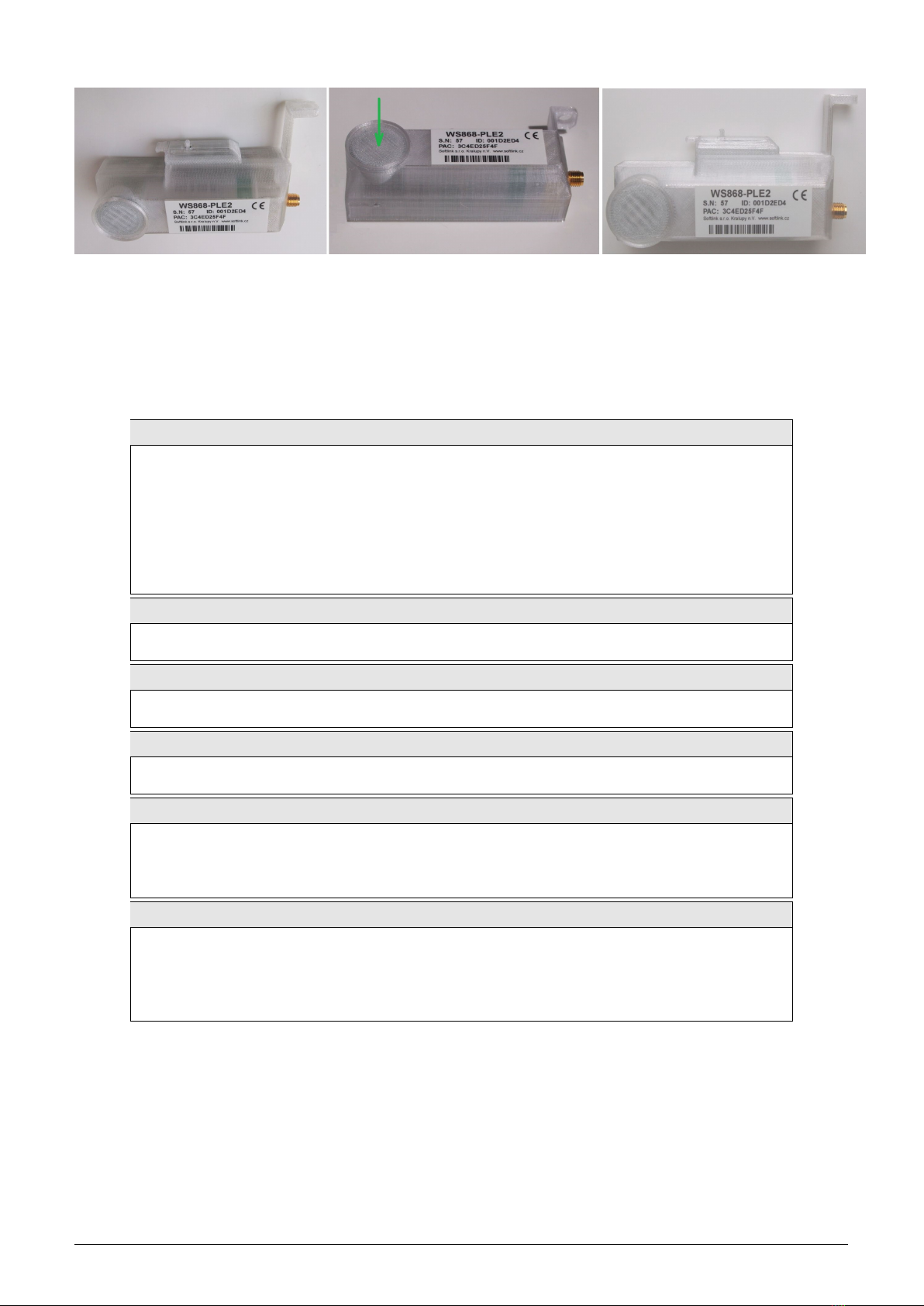
Figure 1: View of the WS868-PLE2 module
2 Technical parameters overview
Overview of WS868-PLE2 module technical parameters is shown in the Table1below.
Table 1: Overview of WS868-PLE2 module technical parameters
RF subsystem parameters
Frequency band 868,0 - 868,6 MHz
Modulation DBPSK
Sub-channel bandwidth 100 Hz
Transmitting power 16 mW
Communication protocol Sigfox
Transmission speed 100 Baud
Antenna connector SMA female
Antenna characteristic impedance 50 Ω
Optical configuration interface
Transmission speed 115 200 Baud
Optical interface specification IrPHY 1.4 standard
Inputs
Magnetic sensor of pivotal wheel revolving index ”0”
Mechanic ”tamper” sensor index ”1”
Power supplying
Lithium battery voltage 3,6 V
Lithium battery capacity 3,6 Ah
Weight and dimensions
Length (w/o antenna connector) 84 mm
Width (w/o sealing protrusion) 40 mm
Height 29 mm
Weight cca 70 g
Storage and installation conditions
Installation environment (by ˇ
CSN 33 2000-3) normal AA6, AB4, A4
Operation temperature range (-20 ÷40) ◦C
Storage temperature range (0 ÷40) ◦C
Relative humidity * 95 % (w/o condensation)
Degree of protection * IP20
WS868-PLE2 2
3 Configuration of the WS868-PLE2 module
Configuration parameters of the WS868-PLE2 module can be displayed and changed from a common computer
(PC) wirelessly, with using of ”USB-IRDA” optical converter. Technique of interconnection of the ”USB-
IRDA” converter with PC and general rules of configuration with using of this optical converter are described in
the section 3.1 ”Configuration of the WS868-PLE2 module with using of optical converter”. The description and
meaning of the parameters that can be changed by optical converter can be found in the section 3.3 ”Setting of
parameters by using of optical ”IRDA” converter”.
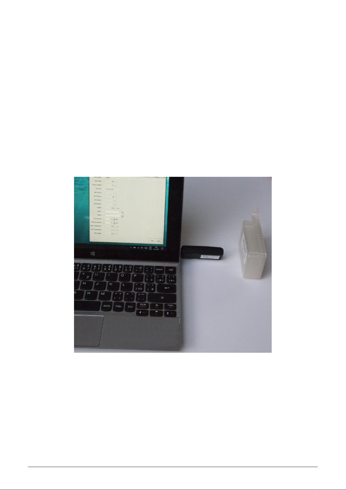
3.1 Configuration of the module with using of optical converter
The module is equipped with an InfraRed interface that is intended for configuration with using of ”USB-IRDA”
converter. This converter serves for wireless transfer of configuration data (commands and values) between module
and configuration computer via modulated beam of light in infrared band. By using of this kind of configuration there
is possible to make all common settings through the transparent casing without necessity to open the module’s cover
(see figure 2). Optical beam goes through the transparent casing and it is decoded by the infrared modem placed
on the module’s printed board (PCB). A special software application program ”WACO OptoConf” written in
Java language can be used for required settings. This program can be installed to the computers with MS Windows
as well as Linux operating systems.
Figure 2: Configuration of the module with using of optical converter
3.1.1 Installation of the ”WACO OptoConf” program
Installation of the ”WACO OptoConf” program can be performed from the ”Optoconf.zip” installation pack.
Copy the pack to any folder of the computer and unpack it by any ”unzip” program. The installation pack contains
following files:
-”optoconf.jar” - executable file of the program
-”lib” - folder with ”library” files
-”README.TXT” - ”readme” file
-”SetupJSerial.msi” - serial port support for Java (installer)
-”ugw3.inf” - driver for USB-IRDA converter
WS868-PLE2 3

The ”WACO OptoConf” program can be started each time by launching of ”optoconf.jar” file (clicking on the file
name or to the created desktop shortcut to this file).
Check whether the ”Java Runtime Environment” (Java Virtual Machine) program in the 8 or higher version is pre-
installed in the computer. If after launching of the ”optoconf.jar” file a Java-window of the configuration program
does not open (or pop-up window ”How do you want to open this file?” appears) then the Java support it is not
installed (or installed in older version) and it is necessary to perform its installation (32-bit version for Windows,
64-bit version for Linux). The Java Runtime Environment program is available on the official Oracle WEB site for
Java support here:
Download Free Java Software
After installation of the Java Runtime Environment install the driver for a serial interface support in Java envi-
ronment by clicking to ”SetupJSerial.msi” file. The installer of driver starts running. The installation is very
simple - it only requires confirmation of necessary changes in computer configuration (”Do you want to allow this
app to make changes to your PC?”). After the driver is installed try to start ”WACO OptoConf” program again
and if everything is all right the program window will be opened. Close the program window.
3.1.2 Connection of ”USB-IRDA” optical converter to computer
Before starting of the ”WACO OptoConf” program connect the ”USB-IRDA” converter to USB port of the
computer. When the converter is connected to computer for the first time an operating system will automatically
find and install correct driver for the converter (i.e. generic driver for ”USB Serial Device” category of device).
After driver is successfully installed to MS Windows computer, the device should appear in the ”Device Manager”
in section ”Ports (COM and LPT)” as ”USB Serial Device (COMx)” (see figure 3).
Figure 3: Displaying of the optical converter in the Windows’ ”Device Manager”
Older versions of MS Windows do not support generic driver for support of serial ports via USB. I this case install
the ”ugw3.inf” driver from delivered installation pack according to the instructions mentioned in the paragraph 3.2
”USB GateWay” and ”USB-IRDA” driver installation” below.
3.1.3 Using of ”WACO OptoConf” program for configuration of modules
Start the ”WACO OptoConf” program by clicking on the ”optoconf.jar” file name or to the pre-created desktop
shortcut to this file. Program window ”WACO configuration” will open (see figure 4). In Config/Port item of
menu choose name of serial port assigned to USB-IRDA converter by operating system (see figure 3). The program
is thus fully functional and ready for configuring parameters. Menu item ”Config/Look and Feel” serves only
for choice of window color and design by clicking to one of pre-configured options.
By clicking to ”Walk device” button the list of all variables that are used for module configuration can be displayed
(see figure 5.
Index and description of all variables of the NEP protocol, that is used for coding of data in Softlink’s ”wacoSystem”
communication systems can be found on the producer’s WEB site NEP Page.
By clicking to ”Read device” button the textbfconfiguration table with all the relevant parameters of the module
is displayed in the working window. Non-configurable (read only) parameters are displayed as ”inactive” (with gray
WS868-PLE2 4

Figure 4: Displaying of ”WACO OptoConf” configuration window”
Figure 5: List of variables in the working window of ”WACO OptoConf” program
editing fields), while parameters that can be changed by ”WACO OptoConf” program are displayed inside white
editing fields (”active fields”). Example of configuration table of the module is depicted in the figure 6.
Figure 6: Example of module’s configuration table in the ”WACO OptoConf” window
3.1.4 General rules for configuration of the module by optical converter
Connect USB-IRDA optical converter to the USB port of the computer. Flashing of green LED signalizes correct
function of the converter. By clicking to ”optoconf.jar” file (or its shortcut) launch ”WACO OptoConf” program.
If not chosen automatically by previous functioning, choose the name of serial port of the converter (”COM XY”)
in the ”Config/port” menu.
Configuration can be performed either on the working desk or directly in the installation site. In both cases it must
be arranged such mutual position of the module and optical converter in which the configured module is not more
than 15 cm from the tip of converter, module’s printed board is facing to converter by its element side and module’s
optical sensor lies approximately in the converter’s axis of symmetry (i.e. in the direction of the infrared beam).
Approximate position of the optical sensor of the module is marked in the figure 1by green arrow. Correctness of
mutual position module/converter can be checked by displaying of the current configuration as described below. It
is necessary to fix and keep such position in which the communication between module and converter is stable and
WS868-PLE2 5

reliable. Do not move with neither computer nor module during configuration. If current modification of the module
is equipped with magnetic attachment for the USB-IRDA converter, it is very easy to use a special modification
of converter equipped with circular magnet. In this case just simply put the converter to the circularly shaped
crater-shaped pit on the module where it is kept by power of magnet, and use USB extension cable.
By clicking to ”Read device” open a configuration table with all the relevant parameters of the module. Parameters
that can be changed are displayed in white colored editing fields. There are four types of editing fields:
- text fields, in which a text can be edited (e.g. ”Info-text” field)
- numeric fields, in which a change of number can be done
- selection fields, in which a choice from pre-set options can be done
- hexadecimal fields (marked by ”hex”), in which hexadecimal characters can be entered
Text fields can be changed by correcting, erasing, or rewriting of the text inside the field.
Numeric fields can be changed by rewriting number inside the field or by its increasing/decreasing with using of
arrows ∆a∇.
Selection fields can be changed by clicking to symbol ∇and choosing required option from the list-box.
Hexadecimal number fields (e.g. ”8B 01”) can be changed by clicking on the character and rewriting its value
to another hexadecimal character (0 to F).
For editing of individual items keep following rules:
•after making any change in editing field there appears symbol ”√” before the field that is an indication of
active change request that will be sent to the module;
•by clicking to ”Write” button in the lower part of the configuration table the program sends configuration
commands through the USB-IRDA converter. During the process of establishing connection converter’s LED
light stops flashing for approximately 2 seconds and then lights-up;
•after sending data to module the program automatically requests a new status of configuration. Displaying of
the new current status of configuration parameters (after requested changes) is signalized by disappearance
of symbol ”√”before editing field;
•if requested change of some parameter is out of its range, the change is not accomplished and after disappear-
ance of symbol ”√”there appears an original value in the editing field;
•the program enables making multiple configuration changes at one time. If there are changes in several editing
fields of the table, each of them is marked by symbol ”√” and after clicking to ”Write” button all the changes
are requested/performed;
•if some of the fields was edited unintentionally (by mistake) and the change of this field is not really requested,
by clicking to symbol ”√” the field can be ”unchecked” and the change request of the parameter is not sent
to module;
•current status of all configuration parameters of the module can be requested anytime by clicking to ”Read”
button in lower part of the table;
•ongoing communication between module and USB-IRDA converter may be signaled by flashing of LED on
the device;
•if the connection between USB-IRDA and the module was not established until several seconds, error window
”Error: Read timeout” will appear in the program window;
•the most common reason of connection failure is either bad position of the module (long distance, wrong
orientation, dirty cover, obstacle in the beam), or the module’s battery was switched off.
NOTE! ”WACO OptoConf” program contains specific data and settings for interworking with certain types of
modules. Each version of the program thus supports only the relevant versions of the wacoSystem modules (i.e.
actual versions of the modules up to date of the software release). If after reading of data from the module the error
window ”Error: Unknown device” will appear, the current version of the program does not support configuration
of this version of the module. In this case it is necessary to download a new version of the ”WACO OptoConf”
program from the product WEB site www.wacosystem.com/podpora, or contact manufacturer’s technical support
3.2 ”USB GateWay” and ”USB-IRDA” driver installation
The driver ”ugw3.inf” intended for support of multiple virtual serial ports through the USB interface of a computer
is a part of delivered installation pack. If your version of MS Windows operating system failed in automatic
installation of a driver for connected ”USB GateWay” or ”USB-IRDA” device, make an installation of ”ugw3.inf”
driver manually.
WS868-PLE2 6

Connect the device to computer and open a window of ”Device Manager” tool. The device appears in the ”Other
device” section in upper part of the window as ”USB Serial port” device (see figure 7left).
Figure 7: Displaying of the device without driver in ”Device Manager” window
By right-clicking to ”USB Serial port” open the context menu and choose ”Update driver software” item. Click on
”Find driver in this computer” in the opened window. Click to ”Select driver from the list” and ”Next” in next
window. After a new ”Select device type from the following list” window appears, select ”Ports (CPM & LPT)” in
the window and click to ”Next” button (see figure 8left). Choose ”From disc” in the next ”Choose driver which
you want to install” window ( figure 8right).
Figure 8: Manual selection of the driver file from a folder
After that a new ”Find file” window appears. Set the folder with driver file in the ”Browse” tool, select ”ugw3.inf”
file name that will appear in the window and click to ”Open” button (see figure 9left). A new ”Choose driver to be
installed for the hardware” window will appear, select ”RFU Gateway Serial port” item and click to ”Next” button
(see figure 9right).
Figure 9: USB driver installation
A new ”Driver software installation” window will appear with standard red ”unknown driver producer” Windows
WS868-PLE2 7

system warning. Click to ”Install the software anyway” option and the installation process will launch (*). After
the process is completed the system shows positive message ”The driver was successfully installed” (or similar).
The device will move to the ”Ports (COM & LPT)” section of the ”Device Manager” window (see figure 7right).
(*) If installing the driver into the Windows 8 or Windows 10 OS computer, it could be a security problem with
the installation because the driver doesn’t have a digital signature (”unsigned driver“). In this case follow the
instructions below.
3.2.1 How to disable driver signature enforcement in Windows 8 system
Enforcement of signed driver installation in Windows 8 can be disabled by following procedure:
•by pressing the ”Windows + R” keys open the ”Run” window;
•write a restart command ”shutdown.exe /r /o /f /t 00” into the ”Open” editable field;
•choose ”Troubleshoot” option in the ”Choose an option” window that will pop-up;
•choose ”Advanced options” in opened ”Troubleshoot” window;
•choose ”Windows Startup Settings” in opened ”Advanced options” window and run ”Restart”;
•during the system restart process a window ”Advanced Boot Options” appears, choose ”Disable Driver Sig-
nature Enforcement” option in this window;
•after launching the system install the driver according the above mentioned instructions.
Deactivation of the enforcement of signed driver function of the Windows 8 operating system is functional only
until the next restart of the system.
3.2.2 How to disable driver signature enforcement in Windows 10 system
Enforcement of signed driver installation in Windows 10 can be switched-off by following procedure:
•click to ”Windows” icon in left the bottom left corner of the screen and choose ”Settings” icon;
•select ”Update and security” in ”Settings” window;
•select ”Recovery” in next window’;
•select ”Advanced startup” section in ”Recovery” window and click to ”Restart” button in the section;
•in a few seconds the new ”Choose an option” screen appears; select ”Troubleshoot” option;
•in next steps select ”Advanced options” and ”Startup repair” options and click to ”Restart” button;
•in this step an instruction for entering of ”BitLocker” recovery key could appear (depends on the system
settings). This is a 64-character access key for data section of the user that can be used in case of loss of OS
Windows password. The key can be found in the ”Microsoft Account Settings” page, that can be displayed by
clicking to ”Windows” icon and ”User” item of main Windows menu. To get to the account it is necessary to
click to ”Change account setting” and ”Manage my Microsoft account” and log into the account by using of
Microsoft user login/password. Select ”Device” in main menu of the user account page and click to ”Obtain
BitLocker recovery key” in ”Desktop” section and ”Bitlocker” subsection. The new screen with recovery keys
will open. Copy down the key that is valid for the required unit (according to the required unit identifier);
•after entering of the key the new screen with startup options will appear, select ”Disable Driver Signature
Enforcement” option from the list. The selection can be done with using of F1 - F10 keys, for selected option
with order number ”7” press key ”F7”;
•after OS Windows restart perform the driver installation according to the above described procedure.
Deactivation of the enforcement of signed driver function of the Windows 10 operating system is functional only
until the next restart of the system.
3.2.3 Support of older OS Windows versions and OS Linux support
Earlier MS Windows versions (Vista, Windows XP and older ones) do not support sufficiently the installation of
multiple virtual serial ports onto one physical USB port and the current versions of ”USB GateWay” and ”USB-
IRDA” devices cannot be connected to the computers with these operating systems.
There is no need to install any drivers with serial port support to the computer with Linux OS as the Linux system
will automatically use its own generic drivers.
WS868-PLE2 8
3.3 Setting of parameters by using of optical ”USB-IRDA” converter
All parameters that is necessary to set-up during common operation can be configured by optical interface. The
settings can be performed through the translucent casing without necessity to open the module’s cover. This is the
significant advantage especially if the module is already mounted to gas-meter and sealed by antifraud seal, because
it is not possible to remove cover without breaking seal.
Principles of the optical configuration, technique of connection to computer and working procedure with using of
the ”WACO OptoConf” program are explained in detail in the section 3.1 ”Configuration of the WS868-PLE2
module with using of optical converter”.
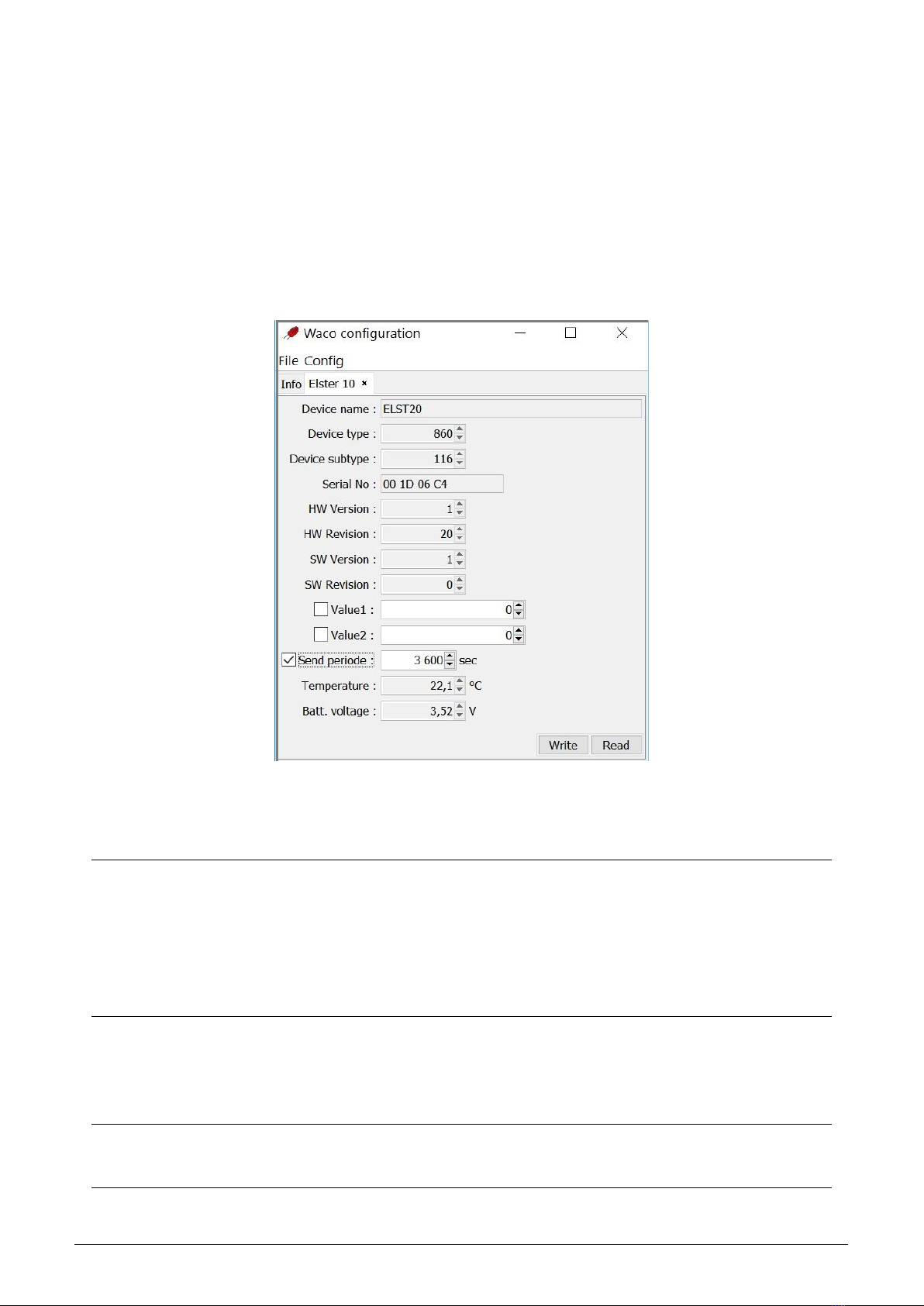
Any changes in module’s settings can be performed in Module configuration table that opens by click on the
”Read device“ button in ”WACO OptoConf” program window. View of configuration table is depicted in figure 10.
Figure 10: The WS868-PLE2 module configuration table
In the upper section of the table there are ”read only” type of parameters (factory settings) that refer to the
identification of the module and its components. There are following parameters:
Device name device name by manufacturer
Device type device type by manufacturer
Device subtype device subtype by manufacturer
Serial No. device serial number (as well MBUS-ID in M-Bus address)
HW Version hardware version by manufacturer
HW Revision hardware revision by manufacturer
SW Version software version by manufacturer
SW Revision software revision by manufacturer
All the parameters contain information about device identification, series and hardware/software version and are
intended only for manufacturer’s use.
In the middle section of the table there is a group of commonly used configurable parameters of the WS868-
PLE2 module. There are following parameters:
Value1 setting of initial value of the first port counter (index ”0”)
Value2 setting of initial value of the second port counter (index ”1”)
Send periode setting of broadcasting period
The ”Value1” parameter is used for setting of the initial (or current) value of internal counter for registration of
WS868-PLE2 9

gas-meter revolving. After this setting the initial value increases by one unit with each turn of gas-meter mechanical
counter.
The ”Value2” parameter is used for registration of tamper status. Current value of this variable (0/1) shows,
whether the tamper micro-switch is connected or released. Setting of this value has no practical meaning.
The ”Send periode” parameter is used for setting of broadcasting period of regular information messages. Value
of the period should be set in seconds.
WARNING!. Frequency of broadcasting in Sigfox network is under regulation. Each device working in Sigfox
network has assigned its service profile that enables only limited number of broadcasted messages per day. Exceeding
this limit can cause some restriction or sanction from the Sigfox service provider. When setting this parameter,
check whether the setting complies with a service contract, that is valid for configured device.
Setting of ”Value1” and ”Send periode” variable can be performed by editing (rewriting) of current value
to required number and clicking to ”Write” button. The process can be observed by flashing of green LED on
the converter and yellow LED on the module. After each writing of new values ”WACO OptoConf” program
automatically re-read actual data from the module, so that if required values will display in the configuration
window at the end (after yellow LED on the module ceases flashing), the process was completed successfully.
In the lower section of the table there are current values of external and internal sensors (temperature, volt-
age...). There are following parameters:
Temperature current processor temperature (read only)
Batt. voltage current battery voltage (read only)
In the non-editable fields ”Temperature” and ”Batt. voltage” there are displayed current values of module
processor temperature and battery voltage. These values are transmitted in each info-message (see description of
information message in section 3.4 ”Structure of WS868-PLE2 module data message”).
3.3.1 Overview of module configuration parameters
Overview of configuration parameters that can be used for user settings of the WS868-PLE2 module is shown in
the Table 2below. The parameters are presented in the same order as they appear in the list of variables obtained
by ”Walk device” command (see paragraph 3.1.3).
In ”OID” column (object ID) there is a variable type according to the ”NEP” coding system invented by SOFT-
LINK. Variable type determines meaning, character and data type of the variable. Multiply used variables have its
”index” (order number) stated in brackets. In the ”Type” column there is a data type of the parameter. In the
”Default” column there are default (factory) settings of the parameter. Colour marking of this field has following
meaning:
•green colour - commonly used parameters that should be set in reliance on the specific usage
•red colour - parameters that are not recommended to change
•grey colour - values that cannot be changed (”read only”)
OID 1 - 8 variables describe device specificatiion data: production type/subtype, serial number, harware and
software version/revision. These data are factory set and cannot be changed by user.
OID=11 variable is reserved for entering of command in texr mode. It has no practical use for WS868-PLE2 module.
OID=12 variable contains an elapsed time from last reset in seconds. By knowing this figure it is possible to
find out when the last reset occurred. Variable is of ”read only” type.
OID=13 variable contains the ”Systime” value, that is module real time. System time is kept in the same format
as in computer operating systems, i.e. in seconds, starting from 1.1.1970 (”UNIX Epoch time”). In default status
(after battery switch-on) there is zero value in the counter and it increases by one every second. As setting of this
parameter is not required for any common application of the module, command for its setting is not included in
the set of configuration commands.
OID=14 variable contains the ”Reset cause” value, that gives an information about the last reset circumstances.
Following reset codes are relevant for this type of device:
-”0” means ”Cold start” (caused by user ”RESET” command)
-”1” means ”Warm start” (based on ”suspension” cause
-”2” means ”Watchdog reset” (reset by ”watchdog“ system)
-”3” means ”Error reset” (incorrect instruction or inconsistent data)
-”4” means ”Power reset” (caused by low power voltage)
The parameter is of ”read only” character and it is used mainly for the diagnostics.
WS868-PLE2 10

Table 2: V´ypis vˇsech konfiguraˇcn´ıch parametr˚u modulu WS868-PLE2
OID N´azev Typ Popis Default.
1 Device name text manufacturer device name read only
2 Device type number manufacturer device type read only
3 Device subtype number manufacturer device subtype read only
4 Manufacturer hex. manufacturer ID read only
5 HW Version number hardware version read only
6 HW Revision number hardware revision read only
7 SW Version number software version read only
8 SW Revision number software revision read only
11 Command text command in text mode read only
12 Uptime number time from last reset (s) read only
13 Systime number system time (s) read only
14 Reset code number last reset code read only
15 Manufacturer ID text device category read only
61 Sequence number current sequence number read only0
90(1) Humidity number current humidity value (*) read only
98(1) Input value type number input counter mode read only0
99(1) Input value level number input counter edge read only0
100(1) Input value number counter current status 0
101(1) Inp. value multiplier number output value multiplier read only1
102(1) Inp. value divider number output value divisor read only1
105(1) Temperature (1) number measured temperature (*) read only
105(2) Temperature (2) number processor temperature read only
106(1) Voltage (mV) number battery voltage in mV read only
109(1) SISA timeouts (1) number broadcasting period (s) 86400
109(2) SISA timeouts (2) number A/D measurement interval read only60
180(1) Sigfox ID text Sigfox network ID read only
181(1) Sigfox PAC text Sigfox PAC-code read only
OID=15 variable contains information about the device category. It is intended only for manufacturer use and
cannot be changed.
OID=61 variable carries a number of last communication sequence. It is intended only for manufacturer use and
cannot be changed.
OID=90 variable contains current value of humidity measured by sensor. As the current module modification is
not equipped by humidity sensor, this variable has no practical meaning.
OID 98 - 102 variables contain setting parameters of counter for registration of gas-meter revolving.
Variable ”Input value” (OID=100) can be used for setting of internal counter initial value. This value increases
by one after each turn of gasmeter pivotal wheel. This variable is factory set to zero value, setting to zero value can
be performed anytime with using of counter reset button. Setting of initial counter value to any number can
be performed with using of optical converter and ”Optoconf” configuration program as described in paragraph 3.3
”Setting of parameters by using of optical ”USB-IRDA” converter”.
Parameters of counter mode and edge are factory preset for WS868-PLE2 module specific usage (registration of
gas-meter revolving) and cannot be changed.
Multiplier and divisor values (output value = counter status * multiplier / divisor) are also factory preset for
WS868-PLE2 module specific usage (working with particular gas-meter series) and cannot be changed. Possible
change of these parameters can be requested upon purchase order.
OID 105 - 106 variables contains current values of measured temperature (Temperature (1)), processor tem-
perature (Temperature (2)) and battery voltage (Voltage). As the current module modification is not equipped
by temperature sensor, the ”Temperature (1)” variable has no practical meaning.
OID=109 variable with index 1 (”SISA timeouts (1)”) can be used for setting of the module broadcasting pe-
riod. The period is set in seconds and the module broadcasts its INFO-messages spontaneously with this period.
Setting can be performed with using of optical converter and ”Optoconf” configuration program as described in
paragraph 3.3 ”Setting of parameters by using of optical ”USB-IRDA” converter”. When setting this parameter,
check whether the setting complies with a service contract, that is valid for configured device (*).
WS868-PLE2 11

(*) Frequency of broadcasting in Sigfox network is under regulation. Each device working in Sigfox network has
assigned its service profile that enables only limited number of broadcasted messages per day. Exceeding this limit
can cause some restriction or sanction from the Sigfox service provider.
OID=109 variable with index 2 (”SISA timeouts (2)”) can be used for setting of the time interval for measurement
of some operational parameters (temperature, voltage...). This interval is factory set for module specific usage and
cannot be changed.
OID=180 variable contains a value of module Sigfox ID, that is an unique identifier of the device in the Sigfox
global network. This ID is permanently assigned to the given module and cannot be changed.
OID=180 variable contains a value of module Sigfox ”PAC” code (Personal Authentication Code), that is an
unique identifier of assigning of the given device to concrete customer - service contractor. Initial PAC-code is
assigned to the module in factory and can be changed only with co-operation with Sigfox network provider (with
possible change of service contractor). Initial PAC-code is written in module configuration as an information for
user. Setting of this parameter has no influence on the module functionality. The parameter is of ”read only” type
and if the PAC-code is changed, it must be recorded in supporting evidence.
3.4 Structure of module data messages
The WS868-PLE2 module is intended for reading of data from Elster gas-meters of BK-G series and broadcasting
of measured data through the Sigfox RF network. Maximum length of standardized Sigfox INFO-messages is 26
Byte, maximum length of data payload is 12 Byte.
The INFO-message broadcasted by WS868-PLE2 module is 26 Byte long and contains 12 Byte long payload with
following information:
P.ˇc. Byte Format Description
1 0 ÷3 32-bit integer, LSB first current status of counter 1
2 4 ÷7 32-bit integer, LSB first current status of counter 2
3 8 ÷9 16-bit integer LSB first temperature in tenth of Celsius
4 10 8-bit unsigned integer voltage battery in mV / 20
5 11 8-bit signed integer relative humidity in per-cent (0 - 100)
”Counter 1” value represents current status of gas-meter input counter.
”Counter 2” value represents current status of tamper (0=not mounted, 1=mounted).
”Temperature” value represents current status of module processor temperature. It indirectly indicates ambient
temperature in installation site.
”Voltage” value represents current status of module battery voltage. It indirectly indicates status of batery
lifetime. The value is indicated in ”mV/20” units, what means that to get the real voltage value in mV, indicated
value must be multiplied by 20.
Example: If there is a ”181” value in the message, real value of battery voltage is: 181 * 20 = 3620 mV.
”Humidity” value represent status of humidity sensor. As this model of device is not equipped with humidity
sensor, ”humidity” value has no practical meaning.
WS868-PLE2 12

4 Operational conditions
This section of the document describes basic recommendations for transportation, storing, installation and operation
of WS868-PLE2 radio modules.
4.1 General Operation Risks
The radio modules are electronic devices power-supplied by internal batteries that register rotation of gas-meter
into the internal counter and broadcast radio-messages with actual gas-meter status.
During their operation be aware mainly of the following risks:
4.1.1 Risk of mechanical and/or electric damage
The devices are enclosed in plastic boxes, so that the electrical components are protected from the direct damage
by human touch, tools or static electricity.
The device is intended for using in normal internal environment. The device is designed for mounting directly to
the mechanical counter slot of the gas-meter reserved for remote reading modules. In normal operation no special
precautions are needed, besides avoiding of the mechanical damage from strong pressure or shocks and protection
against excessive humidity.
If the module is equipped with a remote antenna on a coaxial cable, much attention should be paid for the antenna
and the antenna cable as well. In operation it is necessary to ensure that the antenna cable is not stressed by
mechanical tension or bending. The minimum bending radius of the antenna cable with 6 mm diameter is 4 cm,
for the antenna cable with the 2,5 mm diameter the bending radius is 2 cm. Violation of these bending parameters
can lead to breach of homogeneity of the coaxial cable that can cause reducing of radio range of the device. Further
it is necessary to ensure that the connected antenna cable will not stress the antenna connector of the device by
tension or twist. Excessive loads can damage or destroy antenna connectors.
Installation of the module can be performed only by a person with necessary qualification in electrical engineering
and at the same time trained for this device installation.
4.1.2 Risk of premature battery discharge
The devices are equipped with the long duration batteries. Battery life can be influenced by these factors:
•storage and operation temperature – in high temperatures the spontaneous discharging current increases, in
low temperature the battery capacity reduces;
•frequency of broadcasting.
4.2 The condition of modules on delivery
Modules are delivered in standard cardboard boxes. The modules are commonly delivered in fully operating status
with battery switched on and completed registration in Sigfox Network. For saving battery energy reasons the long
transmitting period (e.g. 1 day) is pre-set in the factory.
4.3 Modules storage
As the modules are already registered in the Sigfox Network on delivery and the subscription period is already
passing, it is strongly recommended to store modules only as short time as necessary. If necessary, store the
modules in dry rooms or halls, in the temperature interval (0 ÷30) ◦C. To prevent the unwanted discharging of
internal battery it is recommended to keep the long transmitting period configured until the module’s installation.
IMPORTANT WARNING Sigfox Network services are charged on the base of prepaid subscription, when each
individual device can be operated only until the end of subscription period and then it is automatically deactivated.
Operation of the module is the most economical in case the module was put into operation immediately after delivery
and it is kept in operation for all the subscription period.
WS868-PLE2 13
4.4 Safety precautions
Warning! Mechanical and electrical installation of the WS868-PLE2 module can be provided only by a person
with necessary qualification in electrical engineering.
4.5 Environmental protection and recycling
The equipment contains non-rechargeable lithium battery. It is necessary to remove battery before module disposal
and dispose battery separately in compliance with the dangerous waste disposal rules. Damaged, destroyed or
discarded devices cannot be disposed as household waste. Equipment must be disposed of in the waste collection
yards, which dispose electronic waste. Information about the nearest collection yard can be provided by the relevant
local (municipal) authority.
4.6 WS868-PLE2 module installation
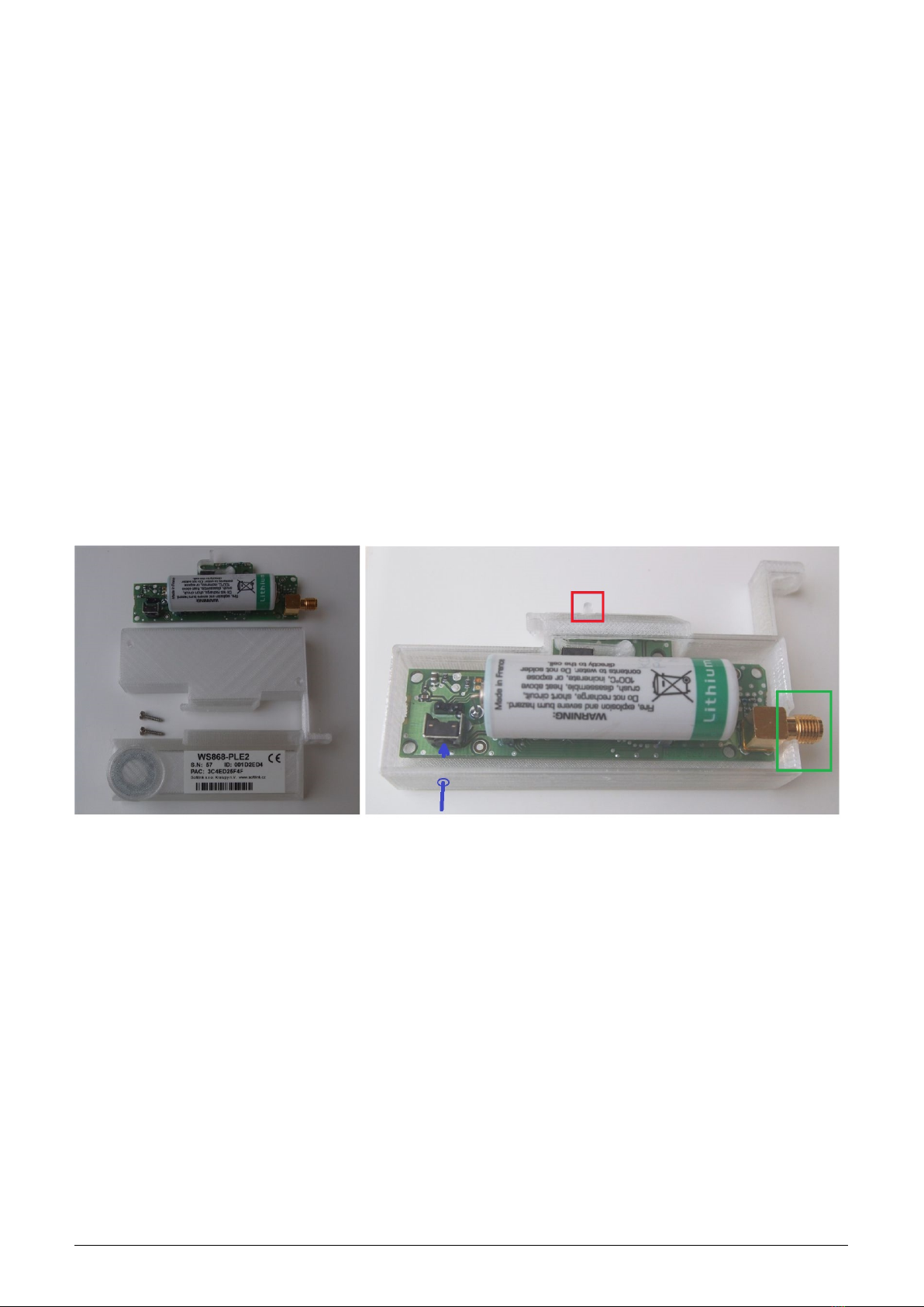
WS868-PLE2 radio modules are enclosed in plastic casings with IP20 degree of protection. The case consists of two
parts:
- back cover with locks for attachment to gas-meter
- front lid with production tag and circular hollow for configuration converter
Both parts are screwed together by two screws and there is no reason to dismantle the casing during normal opera-
tion. View of assembled WS868-PLE2 module is displayed in the figure 1. View of all components of disassembled
module (left) and view of module printed circuit board inserted into back cover (right) is displayed in the figure 11.
Figure 11: Detailed view of WS868-PLE2 module
The module is equipped with counter reset micro-switch (button) for setting of internal counters to zero. The reset
switch is accessible trough the circular hole in the lower side of the module back cover as depicted in the figure 1by
blue arrow. Module antenna connector is positioned in the right side of the module (marked by green rectangle),
tamper micro-switch for indication of module detachment from gas-meter is marked by red colour.
The crater-like circular hollow helps for easy positioning of USB-IRDA configuration converter. There is an iron
segment under the hollow, that enables magnetic fixing of converter equipped with permanent magnet in right
position (see figure 12 middle and right).
When mounting the device follow these instructions:
•the module is delivered fully assembled, switched on, and activated in the Sigfox network. It is no reason to
open the casing neither during installation, nor during operation;
•insert the module into the slot under gas-meter counter. L-shaped sealing protrusion should be oriented to
the right and must fit in the protrusion on the right side of the counter. Short plastic protrusion on the upper
left side of the module should be locked inside the gas-meter lock. View of WS868-PLE2 module installed to
gas-meter is displayed in the figure 12 left;
•connect module sealing protrusion with matching protrusion on the gas-meter by sealing screw or sealing wire
(or other prescribed way) and seal the connection by antifraud seal;
WS868-PLE2 14
•if the broadcasting period has been already set and counter initial value should be set to zero value, it is not
necessary to perform any setting. Just set counter initial value to zero by micro-switch as described below;
•counter reset micro-switch is accessible through the small circular hole in the left part of module lower side
(see figure 11 right). Press the reset switch for approximately two seconds by using of convenient tool (the
best tool is 1 mm thick plastic stick prepared and tested in advance). After this time the couner reset is
confirmed by triple blinking of red LED;
•if the broadcasting period has not been set yet, attach the USB-IRDA converter as depicted in figure 12 and
perform setting of broadcasting period and initial counter value as described in paragraph 3.3 ”Setting of
parameters by using of optical ”USB-IRDA” converter”;
•connect antenna (or antenna cable from remote antenna) to the antenna connector. Antenna rod should be
oriented in vertical direction and shoul be situated as far from gas-meter body and other metal objects, as
possible. The best way of antenna swivelling is depicted in figure 12;
•if the module is installed with remote antenna, pay attention to secure installation of antenna cable. The cable
should be protected against mechanical damage as well as against inundation of cable connector by water;
•check sealing of gas-meter by antifraud seal.
After module installation make sure the right module is mounted to right gas-meter and fill in the prescribed
documentation.
All manipulation with the WS868-PLE2 module during installation is in principle the same, as handling with any
other type of authorized remote reading module for Elster BK-G series gas-meter (e.g. IN-Z61).
Figure 12: Installation and setting of WS868-PLE2 module
4.7 Module replacement and dismantling
When there is necessary to replace the module due to the module failure or due to battery discharging follow this
procedure:
•check the antifraud seal before dismantling – the antifraud seal damage must be solved according to the
internal rules of the customer/project;
•unscrew antenna or antenna cable from the module;
•remove connecting element (screw, wire...) between the module sealing protrusion and matching protrusion
on the gas-meter;
•cautiously pull the module out of gas-meter slot;
•mark the module visibly as ”defective”;
•install a new module in the same way as described in paragraph 4.6 above (L-shaped sealing protrusion must
fit to matching protrusion of the counter, short plastic protrusion on the upper left side of the module should
be locked inside the gas-meter);
•connect module sealing protrusion with matching protrusion on the gas-meter and seal the connection;
•check and set broadcasting period and initial counter value as described in paragraph 3.3 ”Setting of parameters
by using of optical ”USB-IRDA” converter”;
WS868-PLE2 15

•connect antenna or antenna cable to the antenna connector and check the antifraud seal;
•write down the new module ID, gasmeter counter status and seal number. Fill in the prescribed service
documentation. If possible, arrange making of all appropriate changes in the database of the remote reading
system immediately.
When dismantling from gas-meter, disconnect antenna cable (if external antenna used), remove sealing connection
and detache the module from gas-meter. After the dismantling, mark the module as ”dismantled” and fill in the
relevant documentation, prescribed for this situation by the internal rules. If possible, arrange deactivation of the
module in the database of remote reading system immediately. Take off an external antenna (if used).
4.8 Functional check of the module
After putting the module into operation (or after each repair and replacing of the module) it is recommended to
check its basic functionality:
•before installation perform physical check of module, antenna and gas-meter and (if possible) examine avail-
ability of Sigfox network radio-signal by Sigfox signal tester;
•after installation to the gas-meter check correctness of reading system by repetitive inspection of counter
current value (”Value1”) by using of optical converter. If there is a real gas consumption in progress, counter
value should change in correspondence with changing of mechanical counter value. Values of physical quantities
(temperature, voltage..) should correspond with reality;
•check setting of broadcasting period;
•perform complex (end-to-end) check of implementation of the module into the remote reading system by
inspection of data rendered by module in reading system database. If the module broadcasting period is quite
long, set shorter period for testing. After testing don’t forget to set correct value of broadcasting
period (in accordance with service contract!.
4.9 Operation of the WS868-PLE2 module
The WS868-PLE2 module performs reading of gas-meter and broadcasting of radio messages fully automatically.
The greatest risks of permanent breakdown of module broadcasting are commonly caused by human activities
within the installation site, especially mechanical damage of the module, excessive humidity or water inundation,
or shading the RF signal by metallic object due to building operations.
To prevent an unexpected breakdown, it is recommended to perform regular monitoring of all broadcasting data,
i.e. readings, processor temperature and battery voltage. If some of the parameters goes beyond the common steady
value, it is recommended to contact the installation site caretaker and ask for the potential cause of the anomaly
or perform the physical check on the installation site.
The risk of premature battery discharge could be eliminated by respecting the instructions described in para-
graph 4.1.2.
5 Troubleshooting
5.1 Possible causes of module failures
If during operation of WS868-PLE2 module some anomaly, malfunctions or other troubles are recognized, the
possible causes of the failures can be classified by following categories:
5.1.1 Power supplying failures
The module is supplied by electrical power from the long-life internal battery. Approximate battery life is specified
in paragraph 1.3 ”Hardware features”. Battery life can be negatively influenced by circumstances that are described
in detail in paragraph 4.1.2 ”Risk of premature battery discharge”.
Low battery power becomes evident as irregular drop-outs of signal reception from the module, finally the radio
connection with the module completely fails.
Battery is soldered into the printed circuit board of the module and the module has to be disassembled for its
replacement. Battery replacement can be performed only by qualified and experienced person. Soldering of battery
WS868-PLE2 16

by unskilled person can cause irretrievable damage of the module. There are only top-quality batteries used in
the wacoSystem modules, that have been carefully selected and properly tested. In case of battery replacement by
user the new battery parameters should meet same technical requirements (type, capacity, voltage, current load,
auto-discharging current...) as the original battery. It is strongly recommended to use for replacement same type
of battery as used in production.
5.1.2 System failures
As ”system failure” are considered mainly failures of module’s processor, memory, internal supplying or any other
failures that cause a complete breakdown of the device. If module’s battery voltage is correct, with no signs of
discharging and the device still does not communicate through its configuration port and does not respond to
any commands and this status will not change even after module’s restart (by switching off and switching on its
battery), the system failure probably occur. Perform the replacement of the module according to the instructions
in paragraph 4.7 and check functionality of the new module. If the new device works properly, label the original
module as ”defective” and fill in the appropriate documentation prescribed by internal rules for this case.
5.1.3 Reading system failures
Reading system failures typically appear as ”zero consumption” of the gas-meter even though the consumption of
the meter is evident, or generally, meter status from remote reading is considerably different than meter status
shown in meter’s mechanical counter. In this case try to proceed with troubleshooting in following steps:
•visually check whether the module is correctly mounted to gas-meter and whether there are any signs of
gas-meter or module damage;
•if the module is correctly mounted to appropriate gas-meter type and there are no signs of damage or unau-
thorized manipulation, dismantle module from gas-meter and visually check the module and gas-meter again.
If everything looks well, without any signs of damage, replace the module according to the paragraph 4.7;
•if the new module (after replacement) does not work properly as well, the trouble is probaly caused by defective
gas-meter.
5.1.4 Transmitter and receiver failures
If the module is powered by correct voltage, the module communicates through the configuration port, responds
to the configuration commands but the radio-messages from the module are still not received steadily, the possible
reason of the trouble can be a failure of transmitting or receiving of radio signal. The typical indication of trans-
mitting or receiving failures is state of ”partial” functionality with frequent breakdowns in the receiving data from
the module.
All above described troubles could have on common ground, which is unreliability of radio-communication caused
by one of these reasons:
•weak radio-signal of Sigfox network in installation site. RF signal availability can be influenced by weather
conditions (rain, fog..), or by some changes in the transmitting or receiving side (around module installation
site as well as around Sigfox base station).
•permanent or occasional shading of radio signal caused by construction works or any construction changes
within the premises, or by operation around the installation site (moving of machines, cars, etc.);
•permanent, periodical or occasional interference (jamming) of radio signal from external source (another radio
system in the same frequency band, or industrial disturbance);
•low level of transmitting signal caused by transmitter failure;
•low level of receiving signal caused by receiver failure;
•low level of transmitting and receiving signal caused by damage of antenna or antenna cable (if external
antenna used).
If above described indications of unreliable radio-communication become evident, proceed with troubleshooting of
the malfunctioning in following steps:
•visually check surrounding of the installation site to find out if there are any changes that can influence radio
signal (e.g. new objects, things, machines...). If there are such negative circumstances, solve the trouble by
reorganization of the object or by relocation of the module or its antenna (if external antenna used);
•visually check an external antenna and antenna cable (if used), possibly replace these elements for the spare
ones with proven functionality;
WS868-PLE2 17
Table of contents
Other SOFTLINK Conference System manuals


Popular Conference System manuals by other brands

Zte
Zte ZXV10 T700 quick start guide

VADDIO
VADDIO BaseStation 999-8920-000 Installation and user guide

Polycom
Polycom SoundStation2 EX, FX, VS4000 Integrator's reference manual

Lucent Technologies
Lucent Technologies PARTNER II Release 4.1 installation guide

Yealink
Yealink MeetingSpace VC200 quick start guide

Cardo Systems
Cardo Systems SHO-01 user guide


