Brain Bee B-TP 1000 User manual

GB
B-TP 1000
TPMS SCANTOOL
Quick Guide
ENGLISH Ver. 1.3


B-TP 1000
ENGLISH 2
CONTENTS
CONTENTS ................................................................................................................................................................................ 2
GENERAL NOTES .................................................................................................................................................................... 3
MANUFACTURER IDENTIFICATION .................................................................................................................................. 3
TECHNICAL SERVICE CENTRES........................................................................................................................................... 3
DISPOSAL .................................................................................................................................................................................. 3
SYMBOLS ................................................................................................................................................................................... 3
SAFETY INSTRUCTIONS ........................................................................................................................................................ 3
GENERAL TECHNICAL FEATURES ...................................................................................................................................... 5
MARKING .................................................................................................................................................................................. 5
DECLARATION OF CONFORMITY ..................................................................................................................................... 5
EQUIPMENT DESCRIPTION ................................................................................................................................................. 5
ACCESSORIES COMING WITH THE EQUIPMENT ......................................................................................................... 6
DATABASE ................................................................................................................................................................................. 7
DESCRIPTION OF KEYPAD AND CONTROLS ................................................................................................................. 7
MENU STRUCTURE................................................................................................................................................................. 8
MAIN MENU AND STATUS BAR ........................................................................................................................................ 9
CORRECT POSITIONING OF THE EQUIPMENT ON THE SENSOR FOR PROGRAMMING PURPOSES ........ 11
SENSORS READING ............................................................................................................................................................. 11
SENSORS REPLACEMENT ................................................................................................................................................... 12
COPY SENSOR ID ............................................................................................................................................................ 13
CREATE SENSOR ID ........................................................................................................................................................ 14
ENTER SENSOR ID .......................................................................................................................................................... 15
CLONE ALL VEHICLE SENSORS ........................................................................................................................................ 15
CLONE SAVED VEHICLE ...................................................................................................................................................... 15
TECHNICAL INFORMATION .............................................................................................................................................. 16
SENSORS LEARNING PROCEDURES ............................................................................................................................... 16
ACTIVATION, UPDATE AND LICENSE RENEWAL OF B-TP 1000 ............................................................................ 16
The upgrade and license renewal of the B-TP 1000 takes place during the connection of the
scantool to the PC, switching it into "ITALSENSOR TOOL MANAGER" mode and connecting it via the
USB cable. .......................................................................................................................................................................... 16
Installation of ITALSENSOR TOOL MANAGER ....................................................................................................... 16
WARNING: to download updates and allow the program to renew the instrument license, the PC
must be connected to the Internet. .......................................................................................................................... 17
First activation, updating and renewal of the B-TP 1000 license .................................................................... 17
LOW LEVEL PROGRAMMING MODE .............................................................................................................................. 17

B-TP 1000
3 ENGLISH
GENERAL NOTES
All rights reserved. Total or partial copy of this manual is prohibited under any form, either paper
forms or electronic forms. BRAIN BEE SPA and resources used for the drawing up of this manual will
not be held responsible for the incorrect use of the manual, while guarantee that information in the
manual have been duly checked. Products undergo constant control and improvement, hence we
reserve the right to modify information herein without notice.
MANUFACTURER IDENTIFICATION
B-TP 1000 is equipment being manufactured by:
Brain Bee S.p.A.
Via Quasimodo, 4/a
43126 Parma (Italy)
Tel. +39 0521 954411 – Fax +39 0521 954490
e-mail contact@brainbee.com
internet http://www.brainbee.com
TECHNICAL SERVICE CENTRES
As to technical service centres, please view the list on the website www.brainbee.com or contact your
reseller.
DISPOSAL
SYMBOLS
The following warning symbols are aimed at ensuring an easier and simpler consultation of the
manual.
SAFETY INSTRUCTIONS
Precautions for operators safety
Before using the equipment, read and follow the instructions included in the user manual.
Do not use broken or damaged connection cables.
Do not use the equipment in direct contact with heat sources.
Do not use the equipment in environments with explosive atmosphere.
The product complies with the requir
ements of the Community Directive 2002/96/EC.
Disposal shall be made in compliance with local regulations on waste disposal: do not
dump the product with normal household waste but take it to specific collection centres on
the territory, in line with current regulations in force.
Operations representing a situation of potential danger for operators are highlighted using
the symbol shown alongside.
Operations requiring particu
lar attention are highlighted using the symbol alongside. Such
operations shall be performed correctly in order to avoid damaging objects or the
surrounding environment. This symbol also highlights information special attention shall be
paid to.

B-TP 1000
ENGLISH 4
Battery use and safety
Warning: The equipment includes two Li-ion batteries. These batteries can only be replaced by
Brain Bee authorized technical service centre.
Recharge the batteries using the battery charger or the battery power cable supplied with
the equipment.
The user must not remove or replace the battery. The attempt to remove or replace the
battery may damage the battery and cause burns and injuries.
Do not try to disassemble or repair the equipment. The attempt to disassemble or repair the
battery may damage the battery and cause burns and injuries.
Batteries performance is significantly reduced if the equipment is used outside the required
temperature range.
If the equipment is not used for a long period of time, batteries need to be periodically
recharged. If the battery runs completely flat, this will jeopardize its duration.
Do not use damaged cables for connection to the vehicle and comply with the connection-
related instructions.
Improper use of the batteries and failure to comply with the conditions of use indicated
herein might cause risk of fire, deflagration or fluid outflow.
Battery recharge
Notes for the recharge of the product’s internal battery
For an efficient recharge of the battery, the equipment and the battery charger must be kept
at ambient temperature during recharge.
The new batteries are not supplied fully charged.
A new battery or a battery that has not been used in a long time may require a longer
recharge time.
The equipment, the internal batteries and the recharge system are provided with safety
circuits against possible overcharges.
The internal battery is recharged using the battery recharger supplied with the equipment.
During the whole recharge phase, the “IN CHARGE” warning light is ON. Once the recharge
has been completed, the warning light turns off.
When operating on the engine
protect face, hands and feet, with suitable clothes, avoid contact with hot surfaces, such as
sparking plugs, radiators, pipings of the cooling system, exhaust pipes. Catalytic mufflers
reach extremely high temperatures and can cause burns or fires.
Do not smoke and do not use open flames when operating on the engine.
In the vehicles, the cooling fan starts automatically by means of a temperature sensor even
when the engine is off; always pay attention when operating close to it and disconnect it if
needed.
Precautions for equipment use
We recommend a first charging cycle of the battery for at least 8 consecutive hours.
Do not pour water or other fluids onto the system
Protect the equipment from rain or excessive humidity to avoid damaging it irremediably.
The equipment shall never be directly exposed to excessive dust.
Use exclusively original connection cables.
Do not place the equipment on live electrical terminals.
Shall the following technical problems occur, do not use the equipment and contact the
authorized technical service centre or your reseller:
o A fluid has been spilled on the equipment.
o The equipment is not working properly

B-TP 1000
5 ENGLISH
Cleaning of the equipment
For LCD display cleaning, use a soft, clean and dry cloth, spraying a small amount of (non
abrasive) glass cleaner. Rub softly.
Do not spray detergent on the display.
Never use acid base or abrasive cleansers to clean the body of plastic components. Use a
soft, clean and dry cloth, spraying a small amount of detergent and rubbing softly.
GENERAL TECHNICAL FEATURES
TPMS sensors activation:
125kHz (LF) ra
dio transmitter
Sensor parameters reading:
433M
Hz radio receiver
Equipment power supply:
Internal Li
-
Ion battery pack. Battery r
echarge with external 12VDC @
2A power supply unit (supplied with the equipment)
Max. battery life (after
complete recharge)
≈8h without activations
or
> 650 reading cycles
or
> 400 programming cycles
Max. recharge time
4h
User interface:
3,5” TFT LCD display 240x320 16bpp brightness 700cd/m2 and
membrane keypad for equipment control.
Internal memory:
µ
SDcard => 4GByte
Communication ports:
1 USB communication port for
Firmware
update and communication
to PC and/or Touch line diagnostic module.
Operating temperature
:
5°
-
40° C with humidity 0
-
95% without condensation
Dimensions:
210x98x35mm.
Weight:
500g.
MARKING
B-TP 1000 is manufactured in compliance with the Community Directives being relevant and applicable
to its placing on the market. The characteristic data of the equipment are described on the rear side of
the equipment itself. The equipment meets the requirements of the R&TTE Directive 1999/5/EC
It is prohibited to remove damage or tamper with the equipment “data plate”.
DECLARATION OF CONFORMITY
The declaration of conformity can be downloaded from the website www.brainbee.com/ce, in the B-TP
1000 manuals section.
EQUIPMENT DESCRIPTION
B-TP 1000 is an equipment dedicated to maintenance and diagnosis of both direct and indirect TPMS
systems.
Diagnosis of indirect systems can be done with a scantool of the Touch line connected in bluetooth
mode to the B-TP 1000. Any malfunction is detected using the ABS, ESP rpm sensors: the presence of a
flat tyre can be detected based on the rotation speed of every single tyre.
Diagnosis of direct TPMS systems (pressure and temperature sensors fitted in each tyre) includes the
following functions:
Sensor wake-up via radio (LF 125kHz) with different activation pulse according to the specific
sensor, or by deflating the tyre in the cases indicated by the equipment.

B-TP 1000
ENGLISH 6
Reading of the characteristic parameters of the original sensor via radio (UHF – 433 MHz)
o Battery status
o Sensor ID (both decimal and hexadecimal)
o Tyre pressure
o Tyre temperature
Realignment of TPMS sensors on the vehicle in case of “tyre change” or sensor replacement
o via EOBD with optional B-TP EOBD module
o by means of direct or indirect manual procedures
Universal sensors programming: the function allows programming or setting up the
universal sensors that can be used to replace the original sensor on a vehicle. The
programming or setting up phase of the universal sensor is done with radio transmission in
LF range. The types of universal sensors currently supported are:
o EZ Sensor®, EZ Sensor 2.0® - Schrader
o IntelliSens - Huf
o Sens.it® - Alligator
o Italsensor® - Italmatic
o Alcar by Schrader – Alcar
o EU-PRO/T-PRO, EU-PRO1/T-PRO1, EU-PRO2/T-PRO2, EU-PRO Hybryd/T-PRO
Hybryd – Hamaton
o Simple sensor / Direct Fit - Orange
Database with technical information regarding the sensor and tightening torques, original
and universal spare parts codes, and tools codes
Management of automatic updates with UP&GO software
Front vie
w
Bottom view
1.
Antenna
2. LCD display
3. Keypad
4.
USB port
5. Battery charger power input (DC IN)
ACCESSORIES COMING WITH THE EQUIPMENT
Standard accessories may vary according to sales configurations. The items included in the standard
configuration are listed below.
4
5
1
2
3
B-TP 1000
7 ENGLISH
DATABASE
A database of vehicles and associated TPMS sensors with related technical data is stored in the
equipment: maker, model and code of the original sensor, tightening torques of the valve and sensor
fixing nut or screw, codes of the tools required for sensor assembly / disassembly.
Keep the database updated by downloading it from the website and reprogramming the equipment
using the USB cable supplied, as outlined in the paragraph ACTIVATION, UPDATE AND LICENSE
RENEWAL OF B-TP 1000.
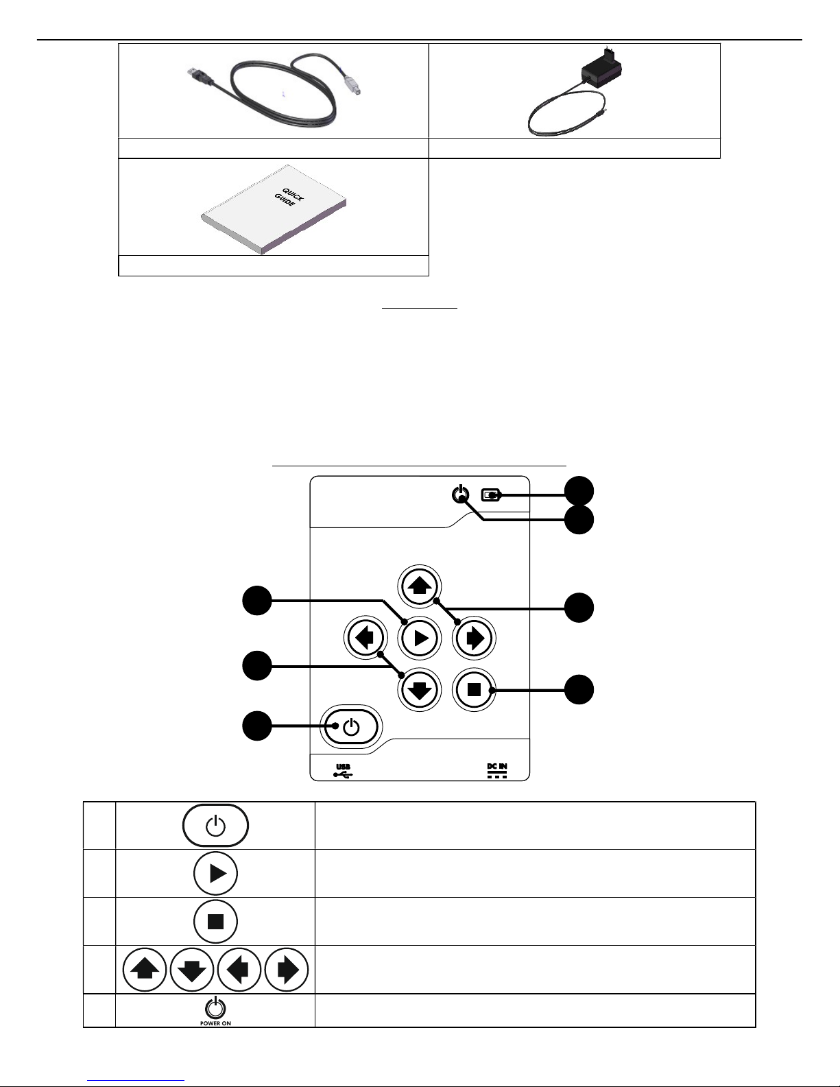
DESCRIPTION OF KEYPAD AND CONTROLS
1
ON/OFF key: press to turn on the equipment. Keep it pressed for
at least 2 seconds to turn off the equipment.
2
OK key: press to confirm your selection or to access the menu.
3
ESC key: press to exit the menu.
4
Arrow keys: press to navigate inside the menu to the left, to the
right, up and down.
5
Power on light: It turns on when the equipment is ON.
USB CABLE
BATTERY CHARGER
QUICK GUIDE
1
4
2
3
4
5
6

B-TP 1000
ENGLISH 8
6
Battery charging warning light:
when the equipment is
connected to the battery charger, the light turns on when the
battery is recharging and turns off when the battery is charged.
PROGRAMMING MODE
+
By pressing the
ESC
key and the
ON/OFF
key, the equipment is
started in programming mode: see paragraph LOW LEVEL
PROGRAMMING MODE
MENU STRUCTURE
The diagram above shows the schematic structure of B-TP 1000 software menus.
VEHICLE
SELECTION
SYSTEM
INFO
SETUP
REPORT
PRINT
MAKER MODEL SENSORS READING
SENSORS
REPLACEMENT
TECHNICAL
INFORMATION
LEARNING
PROCEDURES
MANUAL: DIRECT
TPMS
MANUAL:
INDIRECT TPMS
SERIAL NUMBER
SW VERSION
LICENSE DATA
MAC ADDRESS
LANGUAGE
UNITS OF MEASURE
GARAGE DATA
POWER SAFE
RESERVED
LAST
SELECTIONS
TEST RADIO
CONTROLS
CLONE
SAVED
VEHICLE
UP&GO
CLONE ALL
VEHICLE
SENSORS
B-TP 1000
9 ENGLISH
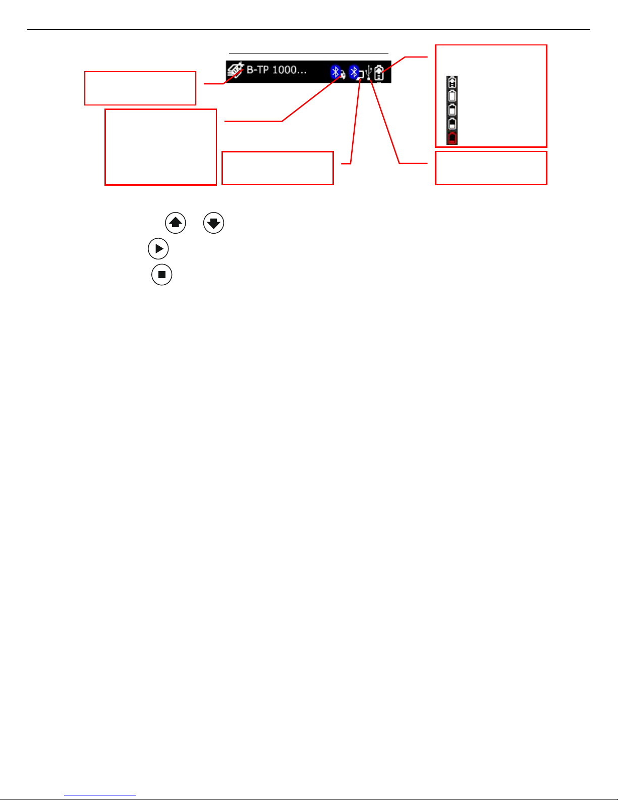
MAIN MENU AND STATUS BAR
When switched on, the equipment shows the main menu:
Press the arrow keys or for menu selection.
Press the OK key to confirm your selection or access the menu.
Press the ESC key to exit the menu.
The top status bar shows the selected menu during navigation or the selected vehicle during sensors
reading or programming. The icons top right show the status of the equipment battery and the
connection to the different devices via bluetooth or USB.
VEHICLE SELECTION is used to select maker, model and production year of the vehicle and
the function to be run:
o Sensors reading is used to read the pressure and temperature values measured
by the sensor inside the tyre
o Sensor replacement is used to program the type and ID number of the sensor
o Clone all vehicle sensors is used to program all the set of sensors in a sequence
after the reading phase on the vehicle
o Technical information shows information as to the technical characteristics of the
sensor and tightening torque for assembly, as well as the codes of the original or
universal spare part
o Learning procedures show instructions as to the learning procedure of the
sensor, which may be of manual type, or may require the use of the diagnostic
tool.
LAST SELECTIONS show the last vehicles selected, which can be easily re-selected
SYSTEM INFO includes serial number, software and hardware version, Bluetooth MAC
address and firmware version of the equipment
SETUP is used to set:
o language of the equipment
o the units of measure for measured pressure (Psi or bar) and measured
temperature (°C or °F)
o garage data for report printing
o auto-off timer
o reserved menu (requires password)
REPORT PRINT manages the report printing with the set garage data
TEST RADIO CONTROLS manages the radio controls test
CLONE SAVED VEHICLE it is used to write all the set of sensors starting from the data
stored into the tool in a previous session
Indicates the battery
status:
charging
100% charged
75% charged
50% charged
running out
Indicates USB
connection to the PC
Indica
tes
bluetooth
connection to the
PC
Indica
tes
bluetooth
connection to the
EOBD port of the
vehicle by means of
B
-
TP EOBD (optional)
Indi
ca
tes menu or
vehicle selected

B-TP 1000
ENGLISH 10
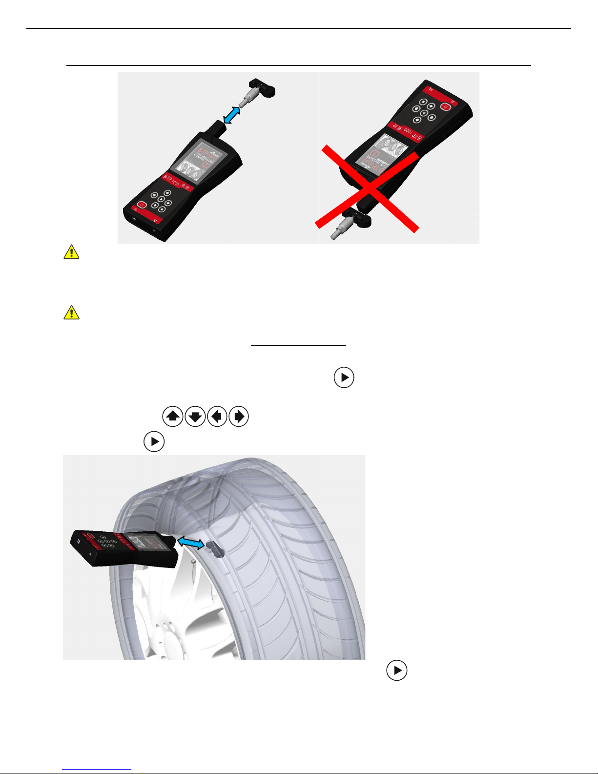
CORRECT POSITIONING OF THE EQUIPMENT ON THE TYRE FOR READING PURPOSES
The correct positioning of the equipment on the sensor ensures the radio communication for the
activation and decoding of the sensor itself. Position the equipment on the tyre, at the same height as
the TPMS sensor, directing the aerial towards the sensor, as shown above. DO NOT touch the metal
rim, which may act as a shield for radio waves, but rather direct the equipment through the tyre.
B-TP 1000
11 ENGLISH
CORRECT POSITIONING OF THE EQUIPMENT ON THE SENSOR FOR PROGRAMMING PURPOSES
Warning! We recommend programming the sensors before installing them onto the tyre.
Position the equipment in line with the valve, in contact with it or at a distance not greater than 5 cm.
Warning! Do not position the equipment on the backside of the valve next to the sensor body.
SENSORS READING
To wake up and read the parameters of the TPMS sensors, you need to select the vehicle (maker and
model), select “SENSORS READING” and confirm using the to access it: the tyre selection menu
will be shown.
Using the arrow keys , select the chosen tyre: the arrow and specific dial will turn
on. Press the key to confirm the sensor reading position.
Position the equipment close to the selected sensor and press the key to start the reading
procedure. The following items will be shown:
Sensor battery status
Identification number of the sensor in hexadecimal code (hex ID) and in decimal code (dec
ID)
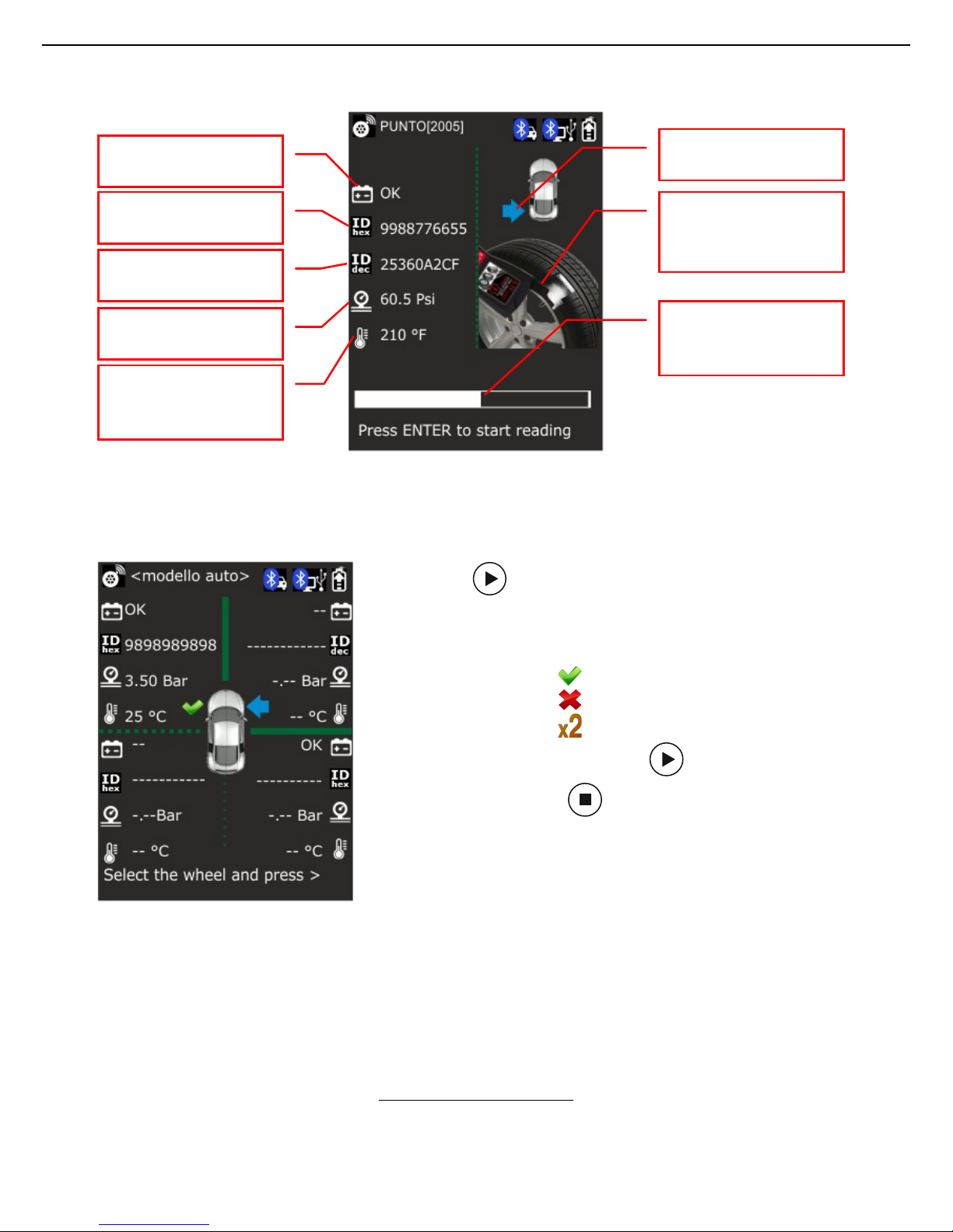
B-TP 1000
ENGLISH 12
The pressure measured by the sensor in Psi or bar according to the equipment settings
The temperature measured by the sensor in °C or °F according to the equipment settings
Press the key to return to the tyre selection menu:
back from the reading page, the next dial (clockwise) is selected.
In the dial corresponding to the read sensor, the icon with the
reading result is shown near the tyre
a. sensor detected
b. sensor not detected
c. IDs duplicated
In case of non-detected sensor, press to run the reading
procedure again, or press to exit the tyre selection menu:
make sure you have positioned the equipment aerial
close to the sensor valve of the selected tyre.
Make sure you have selected the right vehicle
If the sensor is still not being detected, it may be faulty
or not properly set.
In case of duplicated IDs:
make sure you have read the sensor indicated by the blue arrow on the related dial
make sure there are no sensors programmed with the same ID number
IMPORTANT: there can't be duplicated sensors on the vehicle, otherwise the ECU cannot distinguish
the origin of the measured values. In case of duplicated sensors, one of these will have to be
reprogrammed with a different ID code.
SENSORS REPLACEMENT
If you need to replace a TPMS sensor with a universal sensor, you need to program it with an ID code
so that it can be acknowledged by the car ECU.
Warning! We recommend programming the sensors before installing them onto the tyre.
Indica
tes the status of
the
sensor
batter
y
Indica
tes the sensor
ID
number (decimal)
Indica
tes the tyre
press
ure
Indica
tes the tyre inner
temperature
Indica
tes the sensor ID
number (hexadecimal)
Indica
tes the position of
the selected senso
r
Indica
tes the aiming of
the aerial at the sensor
Indica
tes the reading
progress bar

B-TP 1000
13 ENGLISH
To access the programming page:
select the vehicle (maker and model)
select the “SENSORS REPLACEMENT” menu and confirm with the key
select the sensor manufacturer and confirm with the key
select the type of programming to be run and confirm with the key on:
o copy sensor ID: allows copying the ID code of the faulty sensor to be replaced (if
it can be read using B-TP 1000) and programming it into a universal sensor
o create sensor ID: allows creating a random ID code to program a universal sensor
o enter sensor ID: allows entering an ID code using the keypad to program a
universal sensor
IMPORTANT: the ID code of the faulty sensor can be read on the TPMS valve stem or in the
parameters of the vehicle diagnostic system.
COPY SENSOR ID
Position the equipment close to the faulty sensor whose ID code is to be copied and press the key
to read it. The following items will be shown:
Sensor battery status
Identification number of the sensor in hexadecimal code (hex) and in decimal code (dec)
The pressure measured by the sensor in Psi or bar according to the equipment settings
The temperature measured by the sensor in °C or °F according to the equipment settings

B-TP 1000
ENGLISH 14
Position the equipment close to the universal sensor to be programmed with the ID code previously
copied and press the key .
CREATE SENSOR ID
Position the equipment close to the sensor and press the key to program it with a random ID
code generated by the equipment according to the sensor manufacturer previously selected.

B-TP 1000
15 ENGLISH
ENTER SENSOR ID
Enter the ID code selecting the numbers and letters from the keypad on the screen using the arrow
keys and confirming with the key .
Position the equipment close to the sensor and press the key to program it with the ID code
previously set.
CLONE ALL VEHICLE SENSORS
In case of replacement of all the sensors of a vehicle, it is possible to operate using the cloning
procedure of all TPMS sensors.
As first step, select the model of universal sensors to use for that vehicle;
then proceed with the reading of all the vehicle sensors.
The tool shows that the reading phase is ended when four different sensors have been read; at this
point the programming phase of the universal sensors, sorted previously, begins, one sensor at time.
The indications on the display, both in reading and programming phase, allow the operator to execute
a corret flow of operations.
With this function it is not possible to set different ID codes from the ones read from the vehicle.
CLONE SAVED VEHICLE
In case of replacement of all the sensors of a vehicle, it is possible to operate using the cloning
procedure of all TPMS sensors, starting from data saved on the tool in a previous session.
As first step, select the saved vehicle with the sensors to clone; after that it is requested to select the
model of universal sensors to use.
At this point the programming phase of the universal sensors, sorted previously, begins, one sensor at
time.
The indications on the display, both in reading and programming phase, allow the operator to execute
a corret flow of operations.
With this function it is not possible to set different ID codes from the ones read from the vehicle.

B-TP 1000
ENGLISH 16
TECHNICAL INFORMATION
Once the vehicle has been selected, you can select the
“TECHNICAL INFOS" menu and confirm with the key :
the display will show maker, model and codes of the spare parts
available for the original sensor, tightening torques of the valve
and sensor fixing nut or screw, codes of the tools required for
sensor assembly / disassembly.
SENSORS LEARNING PROCEDURES
This procedure must be used when a sensor ID has been changed or if the position of a sensor on the
vehicle has been changed.
If you need to have the vehicle ECU relearn the ID number of the sensors, you can check in the
equipment database, whether to do it with a manual learning procedure or with an EOBD procedure:
In case of manual procedure, all the steps to be carried out will be shown on the screen: for
some vehicles, you just need to press a button and drive for a certain amount of time;
whereas for other vehicles, you will have to activate the learning procedure and wake-up the
valves using B-TP 1000
In case of EOBD procedure, you will have to connect the optional accessory, B-TP EOBD, or a
device of the Touch line, to the vehicle EOBD socket: B-TP 1000 will read in sequence all the
IDs of the TPMS sensors fitted on the vehicle and will transmit them via Bluetooth to the
accessory connected to the EOBD socket, which will then inform the vehicle ECU about the
new ID numbers or the new position of the TPMS sensors fitted into the tyres.
ACTIVATION, UPDATE AND LICENSE RENEWAL OF B-TP 1000
The upgrade and license renewal of the B-TP 1000 takes place during the connection of the scantool
to the PC, switching it into "ITALSENSOR TOOL MANAGER" mode and connecting it via the USB cable.
Installation of ITALSENSOR TOOL MANAGER
First of all it is necessary to install the program, which will be updated automatically as soon as a new
version is available; for the installation follow the following steps:
1) Turn on the B-TP 1000 instrument
2) Select "SETTINGS" and then select "INSTALL ITALSENSOR TOOL MANAGER ON PC";
Then press
3) Press at the next question and connect the instrument via USB cable to the PC

B-TP 1000
17 ENGLISH
3) Search in Computer resources on PC and open the new disk that has been created
(ITALSENSOR ...)
4) Within the disk, run setup.exe to install ITALMATIC TOOL MANAGER on the PC
5) At the end of the operation, switch off the B-TP 1000 and disconnect it from the PC
6) At the end of the installation, an icon is created on the PC desktop, for the following uses of
the program; an automatic update of the program is also launched, if a more recent version
is available.
WARNING: to download updates and allow the program to renew the instrument license, the PC must
be connected to the Internet.
First activation, updating and renewal of the B-TP 1000 license
The process of activation, updating and renewal of licenses is unique and automatic; it is performed as
follows:
1) Turn the B-TP 1000 on
2) Execute ITALMATIC TOOL MANAGER on PC
3) Connect the instrument to the PC and confirm the desire to connect to ITALSENSOR TOOL
MANAGER. If this option does not appear, select "ITALSENSOR TOOL MANAGER" from the
main menu and press
4) On the PC will appear the request to format a disk: ALWAYS deny this request
5) In the PC program, press the upper right button, in the "Italmatic Tool update" area and wait
for the end of the operations.
LOW LEVEL PROGRAMMING MODE
By pressing the key and the key, the equipment is started in programming mode
Table of contents


