Brain Bee 9000 Bus Plus Operating instructions
9000 BUS PLUS
Mod. 9000 BUS PLUS
Service station for air conditioning systems of vehicles
with refrigerant gas R-134a.
User and maintenance manual
Ver. 1.0

ENGLISH 2 / 73 CAP. 1 - CONTENTS
9000 BUS
Page intentionally left blank

CAP. 1 - CONTENTS 3 / 73 ENGLISH
9000 BUS
PLUS
CAP. 1 - CONTENTS
CAP. 1 - CONTENTS ..........................................................................................................3
CAP. 2 - GENERAL INSTRUCTIONS......................................................................................5
2.1 GENERAL
NOTES...........................................................................................................5
2.2 GENERAL
INSTRUCTIONS ..............................................................................................5
2.3 MANUFACTURER
IDENTIFICATION ................................................................................5
2.4 WARRANTY....................................................................................................................6
2.5 TECHNICAL
SERVICE CENTERS.......................................................................................7
2.5.1 Repairs ..........................................................................................................7
2.6 MARKING......................................................................................................................7
CAP. 3 - SAFETY CONDITIONS ...........................................................................................8
3.1 PERSONAL
SAFETY INFORMATION.................................................................................8
3.1.1 Definitions .....................................................................................................8
3.1.2 Personal safety information .............................................................................8
3.2 IMPORTANT
SERVICE EQUIPMENT SAFETY INFORMATION............................................13
3.3 SAFETY
DEVICES ..........................................................................................................13
CAP. 4 - LAYOUT AND USE OF THE MANUAL ....................................................................14
4.1 USE
OF THE MANUAL ..................................................................................................14
4.2 SYMBOLS....................................................................................................................14
4.2.1 Safety..........................................................................................................14
4.3 GLOSSARY..................................................................................................................15
4.4 GUIDELINES
FOR HANDLING REFRIGERANT.................................................................16
4.4.1 Precautions for refrigerant storage.................................................................16
4.4.2 Refrigerant conditions...................................................................................16
4.4.3 Recycling capacity........................................................................................16
CAP. 5 - GENERAL DESCRIPTION ......................................................................................17
5.1 FRONT
VIEW (EXTERIOR) ..............................................................................................18
5.2 FRONT
VIEW (INTERIOR) ..............................................................................................19
5.3 REAR
VIEW (EXTERIOR)..................................................................................................20
5.4 REAR
VIEW (INTERIOR)..................................................................................................21
5.5 RIGHT
SIDE VIEW .........................................................................................................22
5.6 LEFT
SIDE VIEW ............................................................................................................23
5.7 FRONT
SIDE VIEW........................................................................................................24
5.8 TOUCHSCREEN...........................................................................................................25
5.9 STATUS
BAR.................................................................................................................26
5.10 FUNCTION
KEYS ....................................................................................................28
5.11 ECO
LOCK® QUICK COUPLERS .............................................................................30
5.12 INCLUDED
ACCESSORIES .......................................................................................30
5.13 OPTIONAL
ACCESSORIES .......................................................................................30
5.13.1 AGRI&WORK FUNCTION (OPTION ).............................................................31
CAP. 6 - TECHNICAL FEATURES ........................................................................................32
CAP. 7 - INSTALLATION....................................................................................................34
7.1 EQUIPMENT
INSTALLATION.........................................................................................34
7.1.1 Unpacking 9000 BUS PLUS ...........................................................................34
CAP. 8 - COMMISSIONING ..............................................................................................36
8.1 CONNECTIONS..........................................................................................................36
8.2 P
OSITIONING AND CONNECTION ......................................................................................36
8.3 FIRST
TANK FILLING .....................................................................................................37
8.4 NEW
OIL BOTTLE FILLING............................................................................................38
8.5 TRACER
BOTTLE FILLING ..............................................................................................38
CAP. 9 - SETUP ................................................................................................................39
CAP. 10 - A/C SYSTEM RECHARGE....................................................................................42

ENGLISH 4 / 73 CAP. 1 - CONTENTS
9000 BUS
10.1 REMARKS................................................................................................................42
10.2 NON-CONDENSABLE
GAS DISCHARGE..................................................................43
10.3 QUICK
MODE AND ZERO TOLERANCE RECHARGE MODE.......................................44
CAP. 11 - AUTOMATIC CYCLES ........................................................................................45
11.1 AUTOMATIC
A/C SYSTEM SERVICE ..........................................................................45
11.2 AUTOMATIC
CYCLE (BUSES) ...................................................................................45
11.2.1 Last cycle.....................................................................................................45
11.2.2 User-defined cycles.......................................................................................45
11.3 AUTOMATIC
CYCLE (OTHER VEHICLES)...................................................................45
11.4 V
EHICLE SELECTION FROM DATABASE (FOR OTHER VEHICLES ONLY)......................................45
11.5 L
AST CYCLE...............................................................................................................45
11.6 U
SER-DEFINED CYCLES ................................................................................................46
11.6.1 Automatic cycle parameters configuration ......................................................46
11.6.2 OIL TYPE REPLACEMENT...............................................................................47
CAP. 12 - MANUAL CYCLES..............................................................................................48
12.1 PRELIMINARY
OPERATIONS.....................................................................................48
12.2 RECOVERY..............................................................................................................48
12.3 VACUUM
PHASE .....................................................................................................48
12.4 INJECTION.............................................................................................................49
12.5 FLUSHING
(WITH OPTIONAL ACCESSORIES)....................................................................50
12.6 PRESSURE
CHECK (EXCLUDING BUSES) ...................................................................50
12.7 EMPTYING
HOSES ..................................................................................................51
12.8 NITROGEN
LEAK TEST.............................................................................................51
CAP. 13 - MAINTENANCE.................................................................................................52
13.1 SELF
LEAK TEST .......................................................................................................53
13.2 PRESSURE
ZERO......................................................................................................53
13.3 LONG
LIFE PUMP SPECIAL FUNCTION -VACUUM PUMP OIL CHANGE.....................53
13.4 FILTERS
REPLACEMENT............................................................................................55
13.4.1 DRYER FILTER CHANGE ................................................................................55
13.4.2 MESSAGE FOR FILTERS ALMOST EXHAUSTED ................................................56
13.5 COUNTERS............................................................................................................56
13.6 VESSELFILLING (A/C SERVICE STATION TANK).........................................................57
13.7 NON-CONDENSABLE
GAS DISCHARGE..................................................................58
13.8 MULTIPASS.............................................................................................................58
13.9 SYSTEM
INFORMATION ..........................................................................................58
13.10 MAINTENANCE
OF PRINTER....................................................................................58
13.11 PERIODIC
CHECKS .................................................................................................59
CAP. 14 - DISPOSAL.........................................................................................................62
14.1 A/C
SERVICE UNIT DISPOSAL ..................................................................................62
14.2 RECYCLED
MATERIALS DISPOSAL ............................................................................62
14.3 PACKAGING
DISPOSAL...........................................................................................62
CAP. 15 - SPARE PARTS.....................................................................................................63
CAP. 16 - MESSAGE AND ALARM CODES ..........................................................................64
CAP. 17 - MAINTENANCE FORMS .....................................................................................70

ENGLISH 5 / 73 CAP. 2 - GENERAL INSTRUCTIONS
9000 BUS
PLUS
CAP. 2 - GENERAL INSTRUCTIONS
2.1 GENERAL NOTES
All rights reserved.
This manual may not be reproduced, in part or entirely, either in printed or digital form.
It may be printed out solely for use by the user and operators of the equipment to which it refers.
BRAIN BEE SPA and its staff (authors of the manual) are not liable for any consequences of
improper use of the manual or equipment, and guarantees that the information given in the
manual has been thoroughly verified.
The product can be subject to changes and improvements. Brain Bee reserves the right to change
without notice the information contained in the manual.
2.2 GENERAL INSTRUCTIONS
Pressure equipment undergoes checks before commissioning and periodical checks during
operation in compliance with rules and law provisions in force in the country where the tool is
used.
The operator is responsible for operating the equipment in conformity with local legislation.
The equipment is designed for recovering and recycling R134a refrigerant fluid from A/C systems
of buses, cars and similar vehicles.
The equipment is intended to be used by repair and service garages for buses, cars and similar
vehicles.
This equipment is intended solely for use by professionally trained operators familiar with the
basics of refrigeration, refrigeration systems, refrigerants and the hazards associated with
pressurised equipment.
Acareful reading of the present manual by the owners, the users and the operators is required
for a correct and safe use of the tool.
The user shall not be entitled to open the product since maintenance operations are reserved to
the authorised service center.
2.3 MANUFACTURER IDENTIFICATION
The 9000 BUS PLUS equipment is manufactured by:
Brain Bee S.p.A.
Via Quasimodo, 4/a
43126 Parma (Italy)
Tel. +39 0521 954411 – Fax +39 0521 954490
e-mail cont[email protected]
internet http://www.brainbee.com

CAP. 2 - GENERAL INSTRUCTIONS 6 / 73 ENGLISH
9000 BUS PLUS
2.4 WARRANTY
DEFINITION
The warranty provides for free replacement or repair of faulty components due to fabrication.
APPLICATION
The following warranty conditions are inclusive and substitute and legal guarantees in relation to
failures of conformity, and exclude any other liability of the manufacturer and reseller in relation
to the product. The purchaser may not make any claim other than those envisaged in these
warranty conditions, for damages, reduced price or cancellation of the contract. Once the
warranty has expired, no claims may be made against the reseller or manufacturer.
WARRANTY PERIOD
-12 (twelve) months from the date of online activation by the reseller.
- 6 (six) months for replacement parts
EXCLUSIONS
This warranty is provided on condition of full payment of the purchase price and the purchaser
may not make claim under it if he has suspended payments for any reason whatever. The
warranty does not cover parts found to be defective for reasons of:
1. negligent use (failure to follow the operating instructions):
2. incorrect installation or maintenance;
3. maintenance by unauthorised persons;
4. shipping damage;
5. or any circumstances not resulting from fabrication defects.
The warranty does not cover any work done to install and connect the equipment to its power
supplies and feeds.
The following are excluded from the warranty / advance replacement:
-consumables (including: batteries, paper, filters, oil);
-normal wear and tear.
The warranty is void in all cases of improper use and failure to run the scheduled maintenance
detailed in the manual. Brain Bee S.p.A. accepts no responsibility for any damage deriving from
the non respect of the prescriptions indicated in the instructions and in particular those
concerning the tool installation, use and maintenance.

ENGLISH 7 / 73 CAP. 2 - GENERAL INSTRUCTIONS
9000 BUS
PLUS
2.5 TECHNICAL SERVICE CENTERS
Alist of authorised Brain Bee service centres for CLIMA stations is available on the website
www.brainbee.it
2.5.1 Repairs
In case of failures or anomalies, the user can contact directly or through his own regional
reseller a Brain Bee S.p.A authorised service centre to get help.
2.6 MARKING
9000 BUS PLUS is fabricated in conformity with the Community Directives detailed in the
Declaration of Conformity provided with the pressurised equipment.
The equipment falls in the PED risk category II (97/23/EC).
The characteristic data of the equipment are indicated on the specific data plate applied onto the
equipment side part.
It is prohibited to remove damage or tamper with the equipment “data plate”.
NAMEPLATE
CE MARKING: The present CE declaration is enclosed to the tool. Store correctly and provide on
request.
Fac-Simile

CAP. 3 - SAFETY CONDITIONS 8 / 73 ENGLISH
9000 BUS PLUS
CAP. 3 - SAFETY CONDITIONS
3.1 PERSONAL SAFETY INFORMATION
3.1.1 Definitions
DANGEROUS AREAS:
Any area within or close to the equipment implying risk for the safety and health of exposed
persons.
EXPOSED PERSON:
Any person completely or partially standing in a dangerous area.
OPERATOR:
The person/s charged with operating the machine for its intended purpose.
CLASSIFICATION OF OPERATORS
The operator can be classified according to two main categories, which, in some cases, refer to
one single person:
•The operator charged with the equipment operation has the duty to:
oStarting up and monitoring the machine's automatic cycle;
oCarry out simple setting operations;
oRemove the causes of equipment stop not implying breakings of members but
simple operation anomalies.
•Maintenance technician atechnician trained by an authorised Brain Bee S.p.A. service
centre, capable of working on the machine's mechanical and electrical components with
its guards open to make adjustments and to service and repair it.
USER
Body or person legally responsible for the equipment.
3.1.2 Personal safety information
Brain Bee 9000 BUS PLUS A/C service station is particularly simple and reliable due to its
adjustments and functions. When used correctly it presents no hazard for the operator, on
condition that he observes the following general safety instructions and that the service station is
regularly serviced (incorrect maintenance/use compromise the equipment's safety).
Before operating the service station for the first time, read these instructions carefully. If any part
of the instructions is unclear, contact your reseller or the Brain Bee head offices in Parma. This
service station may be used by only one equipment operator, familiar with A/C and refrigeration
systems and the hazards associated with refrigerants and high pressure equipment.
ENGLISH 9 / 73 CAP. 3 - SAFETY CONDITIONS
9000 BUS
PLUS
WORKPLACE: The equipment must be operated in the open or in a well-ventilated location (at
least 1 air change per hour). The workshop has to be equipped with ventilation systems able to
ensure the air change in every environment area or to carry out a periodical ventilation by
opening the environment areas. Use the tool away from heat sources or hot surfaces . The tool
has not to be used in explosion risk environments (potentially explosive atmospheres). Before
using it, put the tool on a levelled plane and secure position, blocking it with suitable wheel stops.
Do not expose the tool to direct sunrays, heat sources, rain and jets of water. Do not smoke close
to the equipment and during operations (keep at a distance of at least 1 m).
The work area must be monitored by the operator while the equipment is operating.
ATTENTION: the R134a refrigerant fumes/gases are heavier than air and can gather on the floor
or inside cavities/holes and cause choke by reducing the oxygen available for breathing.
At high temperatures, the refrigerant breaks down releasing toxic and aggressive substances,
harmful for the operator and the environment.) Avoid inhaling the system coolants and oils. The
exposure can irritate eyes and the respiratory tract.
ELECTRICAL CONNECTION: Connect the power cord solely to a mains supply which conforms
with the ratings on the machine's nameplate (mounted on its side). Make sure the mains socket is
grounded.
Never use the service station with a defective power cord or a different one from that supplied
with the machine; if damaged, immediately have it replaced with an original spare or equivalent
by a Brain Bee S.p.A. service centre. The service station is equipped with safety switches which
stops voltage supply in case of station components opening. Never rely on these protections only.
Before opening the service station, extract completely the supply cable from the plug, or you can
get an electric shock.
Do not tamper with or bypass the safety equipment and settings.
Do not leave the machine powered up when not in use; shut off the power supply before leaving
the equipment unused for a long time. Do not forget that the tool (pressure tool) must always be
protected.
CAP. 3 - SAFETY CONDITIONS 10 / 73 ENGLISH
9000 BUS PLUS
REFRIGERANTS AND LUBRICANTS - INDIVIDUAL SAFETY EQUIPMENT AND PRECAUTIONS: The
refrigerants and the pressure vessels have to be handled with care, otherwise there will be
possible health risks.
The operator must wear safety glasses, gloves and protective clothing suitable to the work. The
contact with the refrigerant can cause blindness (eyes) and other physical damages (freezing) to
the operator. Avoid the contact with skin; the low boiling temperature (about –26 °C for R134a)
may cause burns.
Further information about safety can be obtained from the safety sheets of lubricant and
refrigerant producers.
Do not inhale refrigerant or oil vapour. Keep away from the vent valves and ventilation coupling,
especially when non-condensable gas is being vented.
Never direct the quick couplings (taps) towards your face or other persons or animals.
OTHER PROHIBITIONS AND USE LIMITATIONS: Use only pure R134a refrigerant, and do not
use it on vehicles containing other types of refrigerants. The mixture with other types of refrigerant
produces serious damages to the conditioning and cooling systems. Mixed gases have to be
disposed of according to the current regulations. Do not use the 9000 BUS PLUS station with
compressed air systems.
Do not modify the calibration of safety devices. Do not remove the seals of the safety valves and
of the control systems. Do not use external tanks or other storage containers that are not
homologated or without safety valves.
Make sure the equipment's aeration and ventilation ports are not obstructed or covered while the
equipment is operating.

ENGLISH 11 / 73 CAP. 3 - SAFETY CONDITIONS
9000 BUS
PLUS
HOSE CONNECTIONS: Hoses may contain pressurised refrigerant. Before changing the service
couplers, check the respective pressures in the hoses (pressure gauge).
Before connection to a car A/C system, to an external tank/vessel, check that the quick couplers
are closed (unscrewed HP and LP valves).
Scrupulously follow the instructions on the equipment's display.
QUICK COUPLERS CLOSING/OPENING:
MAINTENANCE/GENERAL CLEANING: The tool has to be serviced at the intervals indicated by
the tool itself. These controls include also a leak self-test that the tool performs automatically.
The service station maintenance has to be performed according to the procedures described in
this manual and to the current safety regulations.
Use only Brain Bee original parts.
When the equipment requires the dryer filter and the vacuum pump oil change, you have to be
careful in the replacement.
A/C service station maintenance can be carried out exclusively by a trained operator or by a
service man of a Brain Bee certified seller. If the maintenance is not performed according to the
expected schedule, the tool will be blocked.
Do not use chemical agents for the service station cleaning as they could attack the material or
the surface.
Closing (detach from the vehicle):
counter-clockwise
Opening (connect to the vehicle):
clockwise
CAP. 3 - SAFETY CONDITIONS 12 / 73 ENGLISH
9000 BUS PLUS
STOP FOR LONG PERIOD: Store the equipment in a safe place, disconnected from the mains,
away from excessive temperatures, humidity and the risk of damaging impact.
Contact the Technical Service to run a safety shutdown of the equipment, and if scrapping the
unit, to drain and recycle the R134a gas as required by local legislation.
To resume operation, repeat the installation (there is no need to register the unit anew with
www.brainbee.com) and run the commissioning trials and regular operational checks as required
by local legislation.
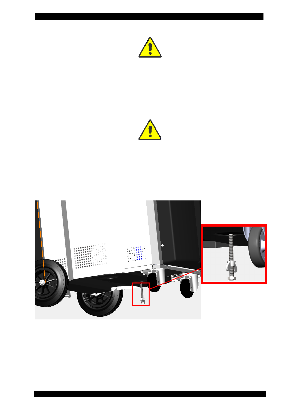
TRANSPORT: If the tool has to be transported, you have to screw the safety screw for the tool
scale fixation. The safety device for transport is on the back of the tool and it consists of a bolt
with wing-nut. Commissioning: Slacken the wing-nut, unscrew the screw for about 4 mm. and fix
it again with the wing-nut. Transport: slacken the wing-nut, screw the screw by hand and then fix
it again with the wing-nut. For the transport of the R134a refrigerant specific regulations are in
force in every country. Therefore, refer to your reseller or your authorised service centre for
information.

ENGLISH 13 / 73 CAP. 3 - SAFETY CONDITIONS
9000 BUS
PLUS
3.2 IMPORTANT SERVICE EQUIPMENT SAFETY INFORMATION
When using the tool, the following operations are not allowed as they might cause, under certain
circumstances, danger for persons and cause permanent damage to the tool itself.
-Do not remove or make unreadable labels, signs and/or dangers signs placed
on the tool and in the area nearby.
-Do not disable the unit's safety equipment.
-Use only fuses identical to the originals as specified on the nameplate; do not
tamper with or attempt to repair the fuses.
If the power supply is known or can be expected to vary beyond the limits
specified for the service equipment, immediately disconnect it.
-The electrical system to which the service equipment is connected must be
configured as provided by local legislation.
-Only operators or qualified staff instructed or certified for the tool maintenance
can open the tool. The equipment contains parts which can cause electrocution:
shut off power to the equipment before servicing/repairing it.
3.3 SAFETY DEVICES
9000 BUS PLUS is equipped with the following safety devices:
SAFETY PRESSURE SWITCH:It stops the compressor in case of excessive
pressure.
SAFETY VALVES: The safety valve opens when the pressure inside the system
reaches a level higher than the fixed limits.
SWITCHES: Switches the equipment off by interrupting the power supply. It is
advisable to pull the power cord plug out of the mains socket in any case
before starting maintenance work.
ANY TAMPERING WITH THE ABOVE-MENTIONED SAFETY DEVICES IS
PROHIBITED.
Failure to observe any of the above safety instructions voids the equipment's warranty.
CAP. 4 - LAYOUT AND USE OF THE MANUAL 14 / 73 ENGLISH
9000 BUS PLUS
CAP. 4 - LAYOUT AND USE OF THE MANUAL
4.1 USE OF THE MANUAL
This manual is an integral part of the equipment and must be kept in the
equipment's immediate vicinity by the purchaser
•If the equipment is sold on to a new user, this manual must accompany it.
•The content of this manual has been drawn up in compliance with the guide lines of the
UNI standard 10893:2000.
•Diffusion, modification or use of this manual for own aims is forbidden.
•The manual uses symbols which call the reader's attention to specific points to facilitate
its use.
•It includes all technical, operating, shutdown, maintenance, spare parts and safety
information.
•In case of doubts on the correct interpretation of the instructions, please contact our
technical service to obtain the required clarifications.
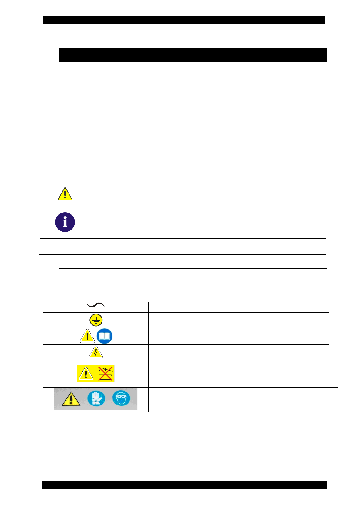
Operations which are potentially hazardous for the operator are highlighted
with this symbol.
Such operations can cause serious injury.
Operations requiring special attention are highlighted with this symbol.
Such operations shall be carried out correctly to avoid causing damage to
objects or to the surrounding environment. This symbol also highlights
information to which special attention must be paid.
Operations which require careful reading of the manual's instructions are
highlighted with this symbol.
4.2 SYMBOLS
This paragraph describes the safety symbols which may be posted on the service equipment's
housing.
4.2.1 Safety
ALTERNATING CURRENT
SAFETY GROUNDING
CONSULT THE INSTRUCTIONS MANUAL
CAUTION! ELECTROCUTION HAZARD
CAUTION !: DO NOT REMOVE THE COVER
(maintenance technicians only)
SEE THE USER MANUAL
USE PROTECTIVE GLOVES
WEAR PROTECTIVE GOGGLES

ENGLISH 15 / 73 CAP. 4 - LAYOUT AND USE OF THE MANUAL
9000 BUS
PLUS
4.3 GLOSSARY
To facilitate the comprehension of the manual, we list below the most important technical terms
used in it.
Refrigerant: Refrigerant fluid used in advanced motor vehicle A/C systems.
The following refrigerant fluids may be used:
oR-134a C2H2F4 - 1,1,1,2-Tetrafluoroethane
A/C system: Motor vehicle air conditioning system.
Equipment: 9000 BUS PLUS service station for recovery, recycling, vacuum, charge of A/C
system.
External tank: Refrigerant bottle used to fill the internal tank.
Internal tank: container for the refrigerant storage.
Phase: Performance of a single function.
Cycle: Sequence of steps.
Recovery: Extraction of refrigerant from the vehicle.
Recycling:Cleaning of the refrigerant, includes: separating out oils, removal of non-condensable
gas and single/multiple pass through filters to reduce the humidity, acidity and particulate
content of the fluid.
Disposal:disposal of refrigerant for storage followed by destruction/scrapping by an authorised
waste management centre.
Vacuum cycle: Draining out of a motor vehicle A/C system and separation out of condensed
matter and humidity, using only the vacuum pump.
Oil injection: Injection of oil into an A/C system to ensure the correct charge as specified by the
vehicle's manufacturer.
Charge: filling of refrigerant into the A/C system in the amount specified by the manufacturer.
System flushing: Cleaning phase for the removal of possible polluting substances from the A/C
system or parts of it.
Non condensable gases: Gas stored in the gaseous phase, including air and nitrogen.
CAP. 4 - LAYOUT AND USE OF THE MANUAL 16 / 73 ENGLISH
9000 BUS PLUS
4.4 GUIDELINES FOR HANDLING REFRIGERANT
4.4.1 Precautions for refrigerant storage
The refrigerant removed from the A/C system must be handled with care to prevent or minimise
the risk of mixing with other refrigerants.
The external canisters used to store the refrigerants must be clearly marked to prevent mixing
different refrigerants.
The canisters must be free of oil and other contaminants.
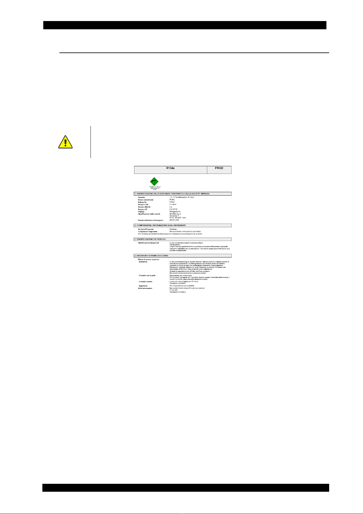
ATTENTION: when handling, using and storing R-134a gas and dealing with
emergency situations, MAKE SURE to refer to the product's safety sheet.
OBTAIN THE SAFETY SHEET FROM YOUR REFRIGERANT SUPPLIER AND
FOLLOW ITS INSTRUCTIONS
4.4.2 Refrigerant conditions
The condition of the refrigerant is critical to the operation of the vehicle's A/C system. Running
repairs properly following failure of damage safeguards the quality of the refrigerant itself
(particulates, acids and water).
4.4.3 Recycling capacity
The service equipment's filtering systems must be replaced regularly (see maintenance messages)
to ensure effective recycling.
Fac-Simile
ENGLISH 17 / 73 CAP. 5 - GENERAL DESCRIPTION
9000 BUS
PLUS
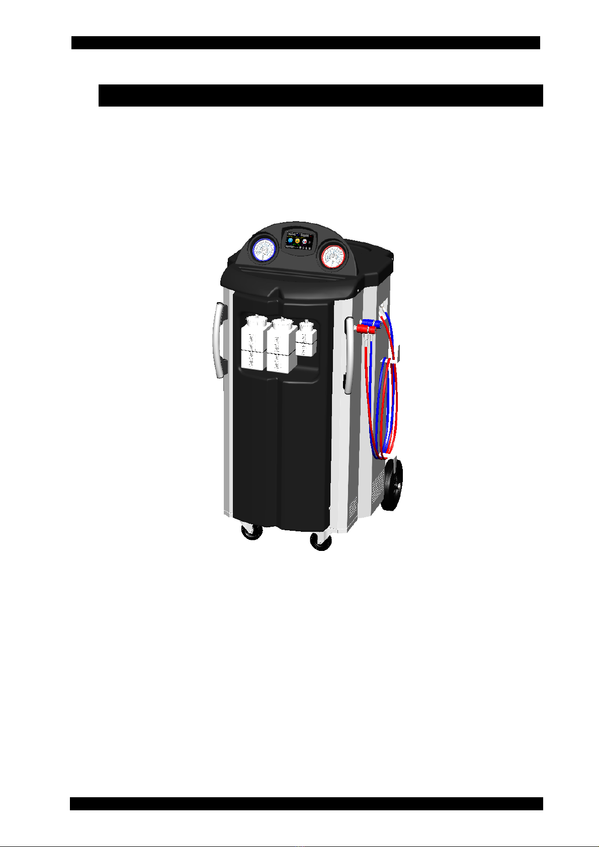
CAP. 5 - GENERAL DESCRIPTION
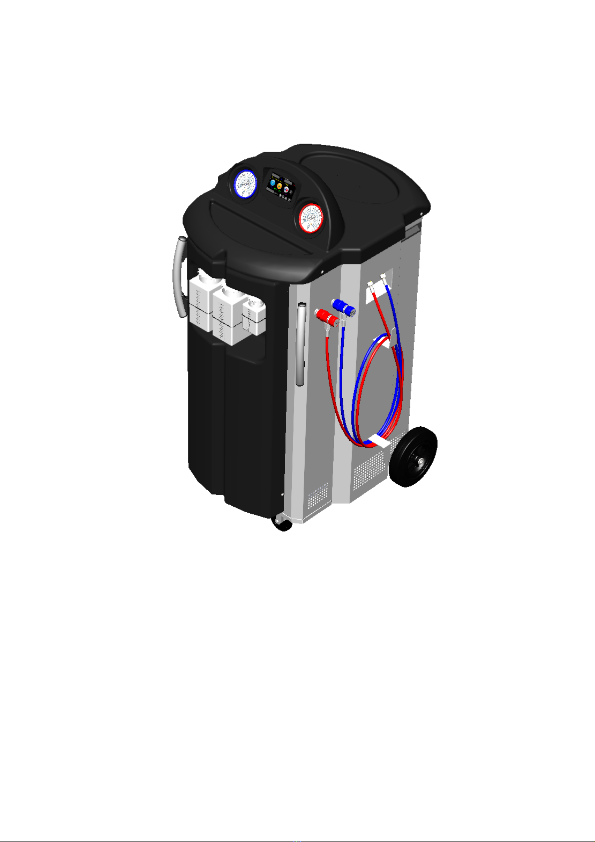
The advanced technology and innovative concept employed in designing and fabricating the
9000BUS PLUS makes it extremely simple and reliable in operation.
With its vessel holding up to 32 kg of refrigerant, 9000BUS PLUS has been specifically designed
for the maintenance and service of vehicle A/C systems containing large amounts of refrigerant,
particularly buses.
However, it can also be used to recharge vehicles with smaller amounts, such as cars.
CAP. 5 - GENERAL DESCRIPTION 18 / 73 ENGLISH
9000 BUS PLUS
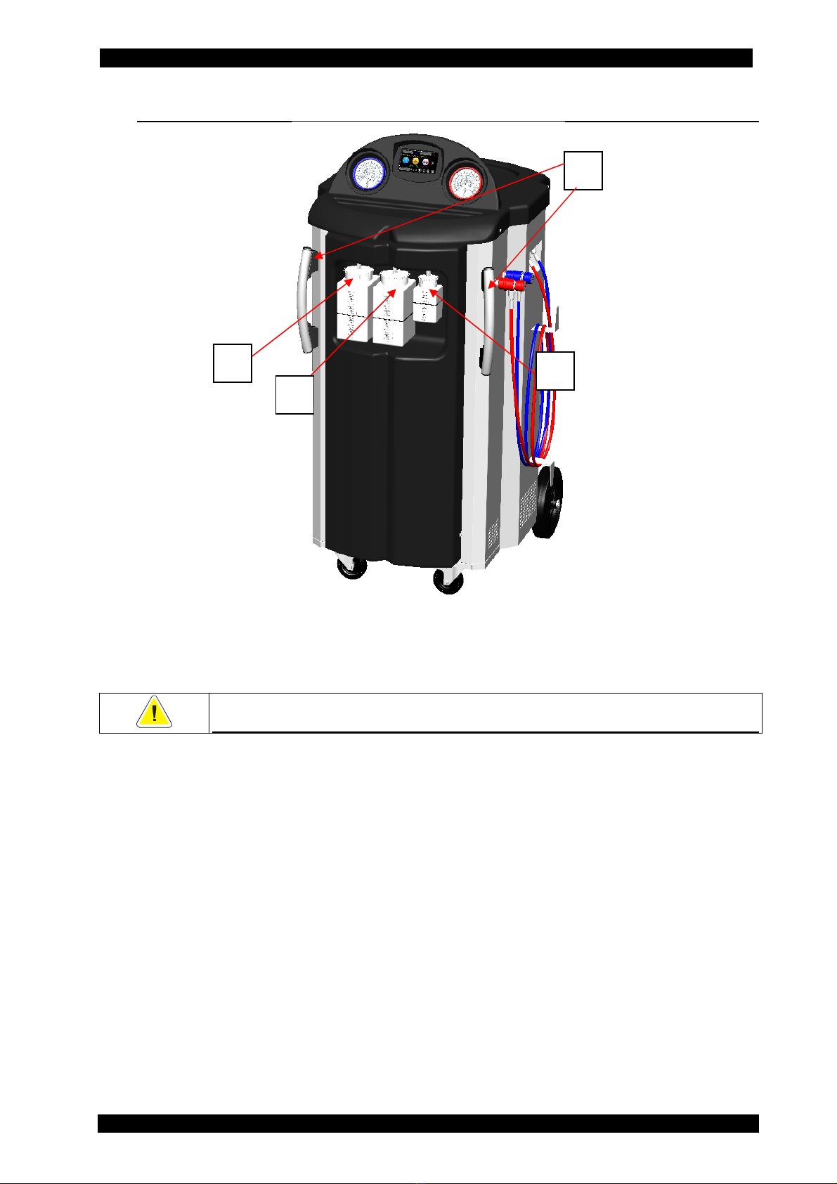
5.1 FRONT VIEW (EXTERIOR)
1. New PAG oil container 1000 cc
2. Exhausted oil container 1000 cc
3. UV contrast fluid container 250 cc
4. Handles
ONLY MAINTENANCE TECHNICIANS MAY REMOVE THE FRONT AND REAR
DOORS OR THE TOP COVER
4
1
3
2
ENGLISH 19 / 73 CAP. 5 - GENERAL DESCRIPTION
9000 BUS
PLUS
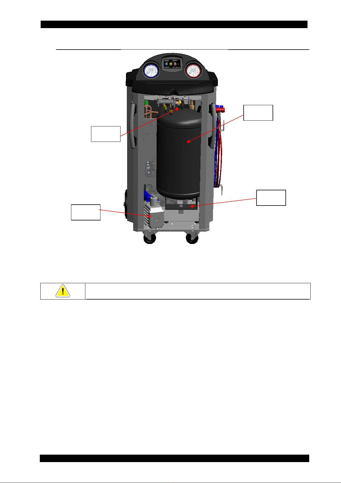
5.2 FRONT VIEW (INTERIOR)
5. Vacuum pump
6. Refrigerant tank 40 L
7. Load cell
8. Non-condensable gas vent valve (automatic)
ONLY MAINTENANCE TECHNICIANS MAY REMOVE THE FRONT AND REAR
DOORS OR THE TOP COVER
5
6
7
8

CAP. 5 - GENERAL DESCRIPTION 20 / 73 ENGLISH
9000 BUS PLUS
5.3 REAR VIEW (EXTERIOR)
9. Caster wheels, with brakes
10. Handling wheels
11. Rear door
ONLY MAINTENANCE TECHNICIANS MAY REMOVE THE FRONT AND REAR
DOORS OR THE TOP COVER
9
10
11
Table of contents
Popular Service Equipment manuals by other brands


BGS technic
BGS technic 70110 manual

Zuwa
Zuwa Solarcheck Mobilcenter P80 operating instructions

Hedson
Hedson IRT-UVA 1 PrepCure 3 Digital Assembly, Operation and Spares Manual

MAC TOOLS
MAC TOOLS WD1500A owner's manual

BGS technic
BGS technic 8640 instruction manual

BGS technic
BGS technic 3001 instruction manual


