Brainchild PC-E User manual

UMPCEC
Rev 3.0, 6/2012
User Manual
Protocol Converter
PC-E, Serial to Ethernet
(RS232/485 Mod us RTU to Mod us TCP/IP)

2
COPYRIGHT NOTICE
This manual is a publication of Brainchild Electronics Co. Ltd. and is provided for use by its
customers only. The contents of the manual are copyrighted by Brainchild Electronics;
reproduction in whole or in part, for use other than in support of Brainchild Electronics
equipment, is prohibited without the specific written permission from Brainchild Electronics
SERVICE
f service is required then pack the unit in its original packaging container or, if unavailable, any
suitable rigid container. f a substitute container is used, surround the unit with shock absorbing
material; damage in shipment is not covered by the warranty. nclude a letter with the unit
describing the difficulty of usage and request Brainchild for RMA procedure.
Send the equipment to the following address:
Brainchild Electronic. Co. Ltd
No. 209, Chung yang Road, Nan Kang Dist, Taipei, Taiwan
Tel: +886-2-27861299
Fax: +886-2-27861395
Email: sales@brainchild.com.tw
All returns will be tested to verify customer claims of noncompliance with the product warranty.
mproper return packaging, which makes verification impossible, will void the warranty. f
noncompliance is verified and is not due to customer abuse or the other exceptions described
with product warranty, Brainchild Electronics will, at its option, repair or replace the Product
returned to it, freight prepaid, which fail to comply with the foregoing warranty, provided
Brainchild is notified of such noncompliance within the one-year warranty period.
ASSISTANCE
This manual is designed to provide the necessary information for trouble-free installation and
operation of your new Serial to Ethernet Protocol converter. However, if you need assistance,
please call Brainchild Electronic Co. Ltd. at +886-2-27861299 Ext 613
Or visit our web site at www. Brainchild.com.tw
Warranty Certificate
For New product: This product is warranted against defects in materials and workmanship for a
period of 12 months from the date of shipment to Buyer. For Rectified Products: Any product
that will be replaced will have Warranty for 6 months or up to Original Product Warranty
period whichever is greater. The warranty is limited to repair or replacement of the defective
unit at the option of the manufacturer. This warranty is void if the product has been altered,
misused, dismantled, or otherwise abused.
ALL OTHER WARRANTIES, EXPRESSED OR IMPLIED, ARE EXCLUDED, INCLUDING
BUT NOT LIMITED TO THE IMPLIED WARRANTIES OF MERCHANTABILITY AND
FITNESS FOR A PARTICULAR PURPOSE.
MAINTENANCE & SERVICE

3
There are no parts that can be serviced by the user. Service should be performed on a unit
substitution basis only. Do not attempt to remove, replace or service any printed circuit board,
components or any hardware/software related with display product. f problem within the
display product occurs, contact the factory for service information or repair.
Any Mechanical or Electrical Modification to this Unit will void
All Warranties
DISCLAIMER
nformation contained herein is subject to change without notice. Every precaution has been
taken in the preparation of this manual. Nevertheless, Brainchild Electronics assumes no
responsibility, express or implied, for errors or omissions or any damages resulting from the use
of the information contained in this publication.
All trademarks belong to their respective owners

4
TABLE OF CONTENTS
1.
Description........................................................................................................................................5
2.
Operating Modes...............................................................................................................................5
2.1
Mode 0 ......................................................................................................................................5
2.1.1
Modbus gateway – Using TCP..........................................................................................5
2.1.2
Transparent Mode – Using TCP........................................................................................6
2.1.
Modbus gateway – Using UDP.........................................................................................6
2.1.4
Transparent Mode – Using UDP.......................................................................................6
2.2
Mode 1 ......................................................................................................................................7
2.2.1
Modbus gateway – Using TCP..........................................................................................7
2.2.2
Transparent Mode – Using TCP........................................................................................7
2.
Mode 2 ......................................................................................................................................7
.
Physical Dimensions.........................................................................................................................8
.1
Grounding/Shielding.................................................................................................................8
4.
Technical Specification.....................................................................................................................9
5.
Wiring ...............................................................................................................................................9
6.
Configuration ..................................................................................................................................10
6.1
Power Connections .................................................................................................................10
6.2
Ethernet Connection................................................................................................................10
6.
Indication LED'S.....................................................................................................................10
6.4
Connecting to a PC which is not Connected to a Network .....................................................11
6.5
Connecting to a PC which is connected to a Network ............................................................12
6.6
Testing the Connection ...........................................................................................................1
6.7
Viewing Web Pages................................................................................................................14
6.8
Troubleshooting Guide ...........................................................................................................15
6.9
Parameter Configuration.........................................................................................................16
6.10
RS485 termination ..................................................................................................................19
6.11
Setting the Jumpers for the RS485 Termination (J5) ..............................................................19
7.
Conformity Certificate ....................................................................................................................21
8.
Examples.........................................................................................................................................22
8.1
Controller to DAQ software via PC-E ....................................................................................22
8.2
IO modules to DAQ software via PC-E ..................................................................................28

5
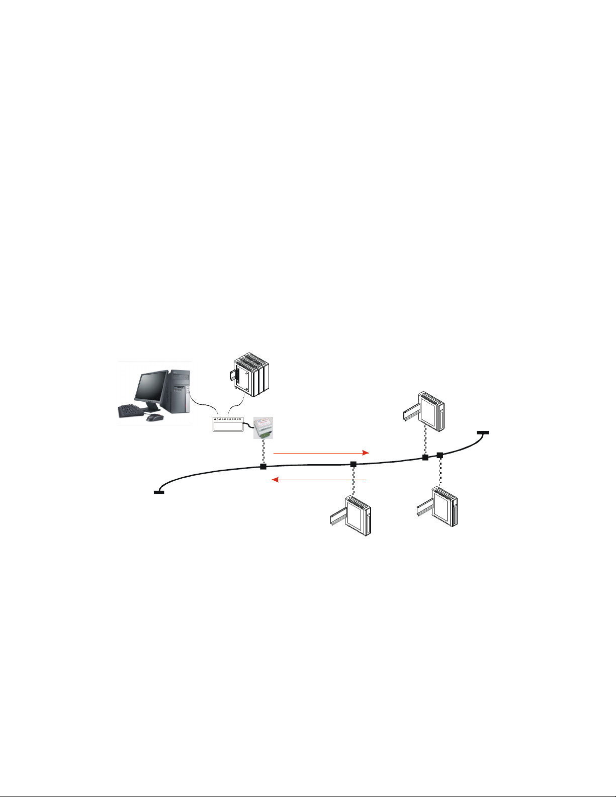
1. Description
The Ethernet/Serial Converter enables serial evices, such as Mo bus base IO mo ules
communicating on RS232/485 to be connecte to a 10/100 Base-TX Ethernet network. The
Ethernet/Serial Converter can be configure to operate in a number of ifferent mo es
epen ing on the application. It can be configure as a transparent ata link or it can perform
the gateway function of converting Mo bus TCP messages to Mo bus RTU messages.
The PC-E converters are factory programme with a efault IP a ress of 192.168.0.112.
This a ress must be change before the converter is a e to an existing Ethernet network.
The IP a ress in the converter shoul be unique in the network an can be change via the
Web Server. Web server allows setting IP a ress, serial ata format an operating mo es.
The web server can be accesse by most web browsers like Internet explorer, Netscape etc.
PC-E supports FTP protocol which enables the web pages to be customize if require .
The web page a ress for viewing the setup parameters is http://192.168.0.112/in ex.htm the
web page a ress for configuring the converter is http://192.168.0.112/ip.htm
The master evice which is polling the mo ules must be configure with the IP a ress of the
converter an with the Mo bus ID of the Mo bus mo ules. As each RS485 network is
separate, it is possible to have repeate Mo bus ID's on the RS485 networks. The IP a ress
ifferentiates between the ifferent RS485 networks. Consequently, many hun re s of IO
mo ules may be a e to an Ethernet network.
2. Operating Modes
2.1 Mode 0
Mo e 0 is the stan ar server configuration for most Ethernet/serial converter applications.
This mo e has been esigne to service multiple sockets which enables up to 4 masters to
communicate with the slaves connecte to the converter.
Each socket is service in turn, an any message in the socket is sent out on the serial port.
The converter then starts a timer waiting for a reply. When a reply is receive the messages
is put into the initiating socket an sen out on the Ethernet network. The converter then
checks the next socket. If no reply is receive then the timer expires an the converter checks
the next socket. This timer is configure on the ip.htm web page an is labele ” Serial Reply
Timeout”.
The converter can also accept messages on UDP instea of TCP. Operation is the same an
oes not nee any special configuration.
There are a number of ifferent configurations for this mo e as follows:
2.1.1 Mod us gateway – Using TCP
When use as a Mo bus gateway the client must be configure to use Port 502. This is a
reserve port number for Mo bus TCP applications an informs the converter that it must
implement the protocol conversion from Mo bus TCP on the Ethernet network to Mo bus
RTU on the serial network.
6
2.1.2 Transparent Mode – Using TCP
When use in transparent mo e the client must be configure to use Port 1234. This port
number informs the converter that any ata that is receive in a socket must be transmitte
out the serial port without any protocol conversion.
2.1.3 Mod us gateway – Using UDP
When use as a Mo bus gateway the client must be configure to use Port 502. This is a
reserve port number for Mo bus TCP applications an informs the converter that it must
implement the protocol conversion from Mo bus TCP on the Ethernet network to Mo bus
RTU on the serial network.
2.1.4 Transparent Mode – Using UDP
When use in transparent mo e the client must be configure to use Port 1234. This port
number informs the converter that any ata that is receive in a UDP atagram must be
transmitte out the serial port without any protocol conversion.
Mod us
Master
PLC
120 Ohm Termination
Mod us
Master
PC
RS485 Network
Digital
Outputs
8DO
8DI
TC
Inputs
8TC
Digital
Inputs
Mod us
Slaves
Request
Response
Ethernet
RS232/RS485
Converter
UTP
Ethernet
Hub/Switch
Fig: Max. 4 masters can access ata of the IO mo ules via PC-E in Mo e 0
Note: Max. 127 IO mo ules can be connecte on each RS485 network
Note: Max. 254 temperature controllers can be connecte on each RS485 network
Note: Combination of IO mo ules an Controllers: Maximum 254 on each RS485 network (IO
mo ules from a ress 1 to 127 only)
Note: If DAQ software is use , it supports maximum 4 banks. Each bank can be connecte
with either RS485 or Mo bus TCP. DAQ software support max. 2048 tags.

7
2.2 Mode 1
Mo e 1 is a server configuration an is similar to Mo e 0 except that this mo e only makes
use of a single socket. By efault, Mo e 1 for simple applications.
Ex: Access IO mo ules ata in one PC via PC-E on Ethernet.
This single socket implementation waits for messages to come in on the Ethernet network
an sen s them out the serial port. Any messages being receive on the serial port are sent
out on the Ethernet network. As there is only one socket, there is no nee for the timer as in
mo e 0.
There are a number of ifferent configurations for this mo e as follows:
2.2.1 Mod us gateway – Using TCP
When use as a Mo bus gateway the client must be configure to use Port 502. This is a
reserve port number for Mo bus TCP applications an informs the converter that it must
implement the protocol conversion from Mo bus TCP on the Ethernet network to Mo bus
RTU on the serial network.
2.2.2 Transparent Mode – Using TCP
When use in transparent mo e the client must be configure to use a PORT number chosen
by the user. This port number informs the converter that any ata that is receive in a socket
must be transmitte out the serial port without any protocol conversion an must not be one
of the reserve numbers 21(ftp), 80(http), 502(Mo bus). This is the mo e that is use to
create a transparent point-to-point serial-Ethernet-serial link with a client converter.
2.3 Mode 2
Mo e 2 is a Client configuration an is use to make a transparent link with a server
converter. This mo e only makes use of a single socket.
This single socket implementation waits for messages to come in on the Ethernet network
an sen s them out the serial port. Any messages being receive on the serial port are sent
out on the Ethernet network. As there is only one socket, there is no nee for the timer as in
mo e 0.
When messages are receive on the serial port they are sent out on the Ethernet network.
Due to the fact that the Ethernet network is normally faster than the serial ata being
receive , the serial message being receive will get broken up into small blocks an then sent
on the Ethernet network. This coul result in the Ethernet network being floo e with many
messages sen ing one or two characters at a time. To prevent this from happening, a timer is
use . This timer starts when the first character is receive on the serial port an when it
expires any receive characters in the serial port buffer are sent out on the Ethernet network.
This timer is isable if a value of 0 is programme . The timer is labele “Char Timeout “on
the ip.htm web page.
The client converter must be configure to use a PORT number chosen by the user. This port
number must be the same which is programme into the server converter. This Port number
informs the converter that any ata that is receive in a socket must be transmitte out the
serial port without any protocol conversion an must not be one of the reserve numbers
21(ftp), 80(http), 502(Mo bus). This is the mo e that is use to create a transparent point-to-
point serial-Ethernet-serial link with a server converter.
The Client converter has to open the socket with the Server converter. In or er to o this, the
IP a ress of the Server must be configure in the Client converter. This is one on the
ip.htm web page an is labele “Server IP”.

8
3. Physical Dimensions
The Converter enclosure is shown below. The mo ule has been esigne with a quick snap-
in assembly for mounting onto DIN-rail’s as per DIN EN 50 022.
106 mm
70.00 mm
59.50 mm
6
0
.
0
0
m
m
4
6
.
0
0
m
m
3.1 Grounding/Shielding
In most cases, the converter will be installe in an enclosure along with other evices which
generate electromagnetic ra iation. Examples of these evices are relays an contactors,
transformers, motor controllers etc. This electromagnetic ra iation can in uce electrical noise
into both power an signal lines, as well as irect ra iation into the mo ule causing negative
effects on the system. Appropriate groun ing, shiel ing an other protective steps shoul be
taken at the installation stage to prevent these effects. These protective steps inclu e control
cabinet groun ing, mo ule groun ing, cable shiel groun ing, protective elements for
electromagnetic switching evices, correct wiring as well as consi eration of cable types an
their cross sections.
1. Screene twiste pair cable must be use with the screen groun e at one point only.
2. Use shoul be ma e of screene I/O, T/C, RTD cable with the screens groun e at one
point as close to the Protocol converter as possible.
9
4. Technical Specification
Power Supply PC-E 90mA @ 10VDC / 40mA @ 26VDC
10/100 Mbits/s 10/100Base-TX Ethernet
Connector RJ45
RS232 3 Wire , TX,RX,GND
RS485 2 Wire Multi rop twiste pair
Bau Rate 2400, 4800, 9600, 19200, 38400,
57600, 115200
Data Bits 5, 6, 7, 8.
Parity None, Even, O .
Serial
Stop Bits 1, 2.
Operating Temperature. -10°C to + 50°C Temperature
Storage Temperature -40°C to + 85°C
Connectors Power an Comms. 8 way screw connector
Humidity Up to 95% non-con ensing.
5. Wiring
Please Note: You must select RS232 or RS485 on the ip.htm we page
7
8
6
1
2
3
4
5
PC-E
+
-
E
12 - 24V DC
LOGIC POWER
INPUT
+COMMS
- COMMS
TO RS485
NETWORK
RJ45
10/100baseTX
RS232 - RX DATA
RS232 - TX DATA
RS232 - GND
10
6. Configuration
6.1 Power Connections
The Ethernet/Serial Protocol converter must be clippe onto a DIN rail. Power for the
Protocol converter PC-E must be applie to terminal 1 (+12/24VDC) an terminal 2 (0V).
The power LED will illuminate an all LED's will be off.
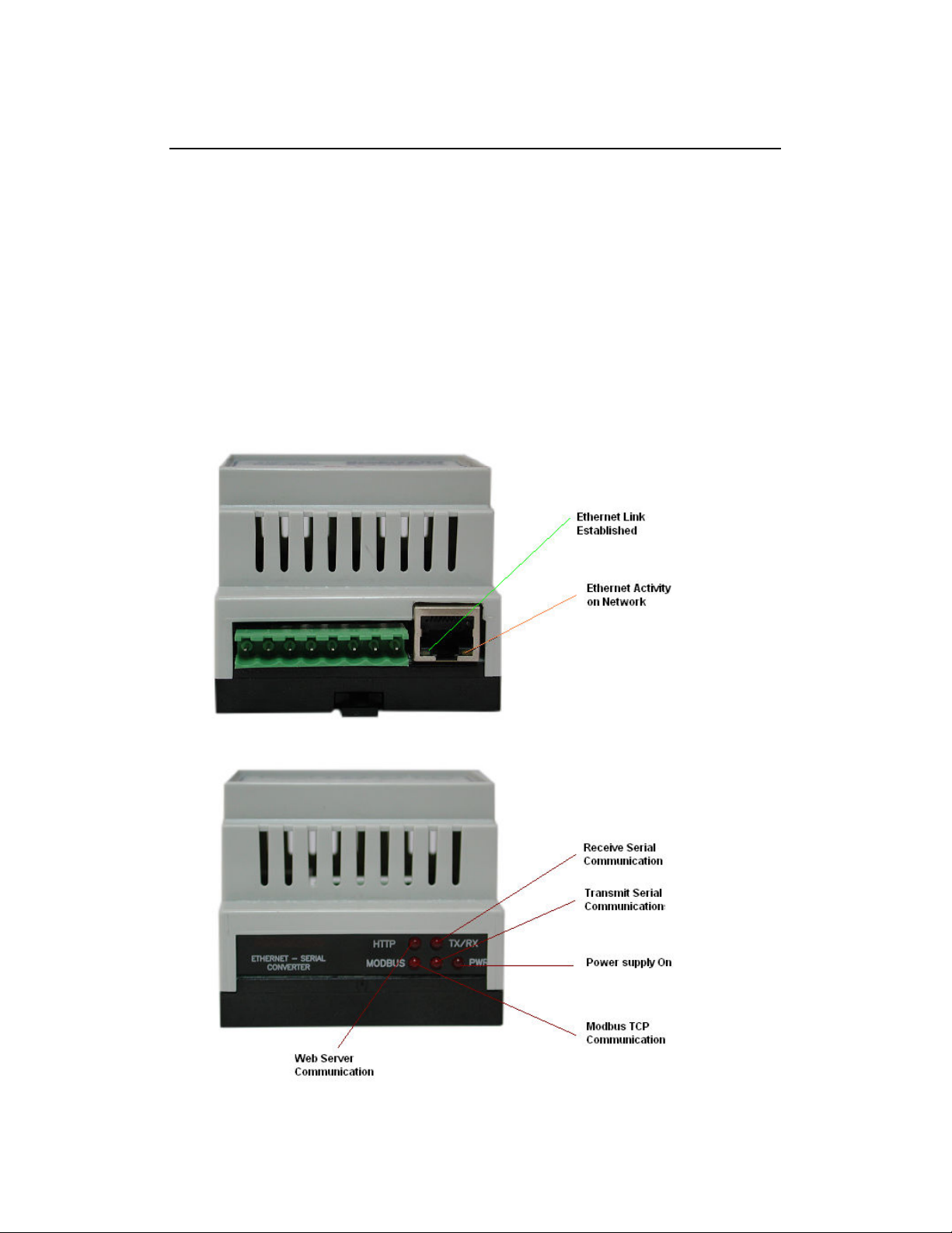
6.2 Ethernet Connection
Next the Ethernet connection is require , either through a network or irectly to a PC. The
Ethernet interface uses a stan ar RJ45 connector.
6.3 Indication LED'S
The le 's on Protocol converter are use to in icate the operation of the mo ule.
11
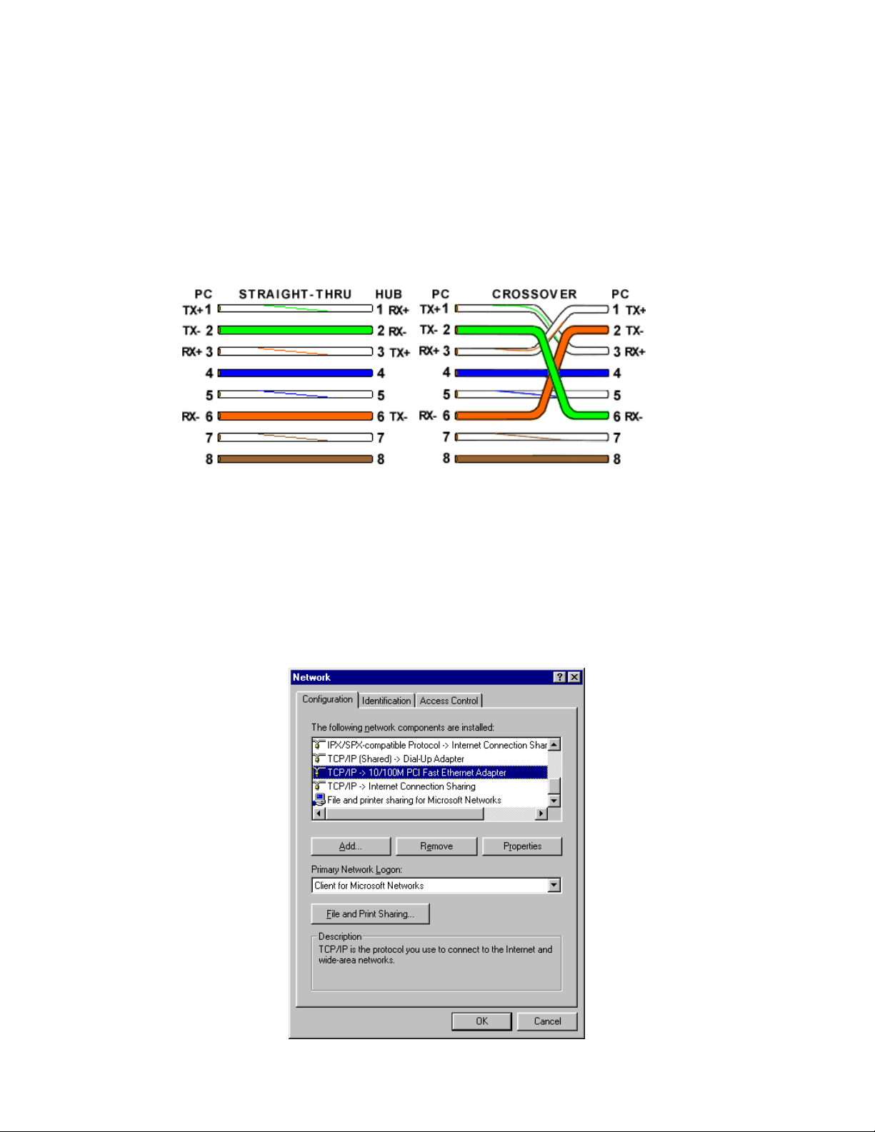
6.4 Connecting to a PC which is not Connected to a Network
If the PC is equippe with an Ethernet car but not connecte to a network, a local
network a ress shoul be use for communication between the Converter an the PC.
The PC-E converter is shippe with a efault IP a ress 192.168.0.112. For irect
connection between the PC an the Protocol converter, a crossover Ethernet cable is
require .
To setup your PC to connect irectly to the Protocol converter PC-E, an IP a ress in the
same range as the Protocol converter must be assigne to the PC. In Win ows
environments, this shoul be one as follows:
• Connect the PC an the Protocol converter together using a crossover cable
• Open the Win ows Control Panel
• Select Network
• Select TCP/IP -> the PC's Ethernet a aptor from the Configuration tab as shown
below

12
• Click the properties button. A TCP/IP Properties box similar to the one below shoul
appear
• Select the IP A ress tab
• Choose to Specify an IP a ress as shown in the figure
• Insert the IP a ress 192.168.0.113 an the correspon ing subnet mask as shown
• Save your settings by pressing OK in both TCP/IP properties an Network properties
• Reboot your PC
6.5 Connecting to a PC which is connected to a Network
If there is an Ethernet network available, the Protocol converter can be connecte to any hub
belonging to the network. Please note that PC-E is shippe with efault IP a ress of
192.168.0.112. To connect PC-E with existing network first IP a ress of PC-E shoul be
change to free IP a ress available in the network.
1. Contact system a ministrator an request for free IP a ress in the network.
2. Remove LAN cable.
3. Change IP a ress to the PC as follows...
IP a ress: 192.168.0.113
Subnet mask: 255.255.255.0
Default Gateway: 192.168.0.1
Enable the network connection.
4. Connect cross over Ethernet cable between PC an PC-E.
5. Apply Power to PC-E
6. Observe that Ethernet link LED, (Green color) is stea y on continuously. Right si e
LED shows link activity an you can observe slow flash.

13
6.6 Testing the Connection
To test the connection between the PC an the Protocol converter, a simple program calle
ping can be use . Ping sen s a number of messages to the specifie IP a ress an isplays
the response. The ping program can be run from the comman line or from a DOS prompt on
the PC, as follows:
• Open the Win ows Start Menu
• Click Run
• In the Open box, type: "ping 192.168.0.112"
If the network connection is OK between PC an Protocol converter, the program will respon
with:
"Reply from 192.168.0.112" an information about the response time
If there is a problem with the network setup the program will respon as follows...
There may be the following solutions to this problem:

14
• Check the Ethernet cable between PC an PC-E. We suggest that it shoul be cross
over cable. You shoul not use LAN cable (straight cable) for this purpose. Check
that the Link LED is illuminate when the cable is plugge into the RJ45 connector.
• Make sure that PC is set with efault IP a ress in the range of efault IP a ress of
PC-E. Ex: You can use 192.168.0.113 for the PC.
• If you wish to use LAN cable only between PC an PC-E then make sure that your
PC is set with IP a ress in the range of PC-E. Set PC with IP a ress
192.168.0.113, subnet mask: 255.255.255.0.
6.7 Viewing We Pages
The Protocol converter has built in web pages. These are use for changing the configuration.
To view these Web pages, a Web browser such as Internet Explorer or Netscape is nee e .
To view the efault Web page in Protocol converter, start the Web browser an type
"192.168.0.112" into the a ress line of the browser win ow. The main page of the Protocol
converter will now be isplaye in the browser win ow.
If no Web page is isplaye , go back to testing the network connection from PC to the
Protocol converter by using the ping comman . If the Protocol converter replies to the ping
messages, check the setup of the Web browser. If the Protocol converter is irectly
connecte to the same network as the PC, " irect connection to the network" or "bypass
proxy server for local a resses" shoul be selecte in the Web browser configuration menu.
If the Protocol converter is connecte to the PC through a firewall, a proxy server shoul be
selecte in the configuration menu. Contact the local network a ministrator for information
about the network configuration.

15
6.8 Trou leshooting Guide
No Checkpoint Solution
No
No network connection is etecte . The Ethernet
cable is either not plugge in or wrong type of
cable is use . For connection to a network with a
hub or switch, a straight through network cable
can be use . For irect connection between PC
an Protocol converter, a cross over Ethernet
cable must be use .
1
Is the LINK LED on an is
the ACTIVITY LED
flashing with short
pulses?
Yes
A network connection is etecte ; the Protocol
converter is connecte to the network.
No
Either the PC or the Protocol converter is setup
with wrong IP a ress. Set PC-E with efault IP
a ress.
To change the IP a ress of a PC, use the
Win ows "control panel -> network -> TCP/IP
properties" an setup an IP a ress close to the
Protocol converter a ress. The Protocol
converter is shippe with a efault IP a ress of
192.168.0.112, the PC can be setup with an IP
a ress of 192.168.0.113
2
Does the Protocol
converter respon to
PING requests?
Yes
The PC an Protocol converter are setup with a
correct IP a ress an they are able to
communicate with each other.
No
This is normally cause by the setup of the Web
browser.
In the "options" or "preferences" menu, check that
the Web browser is configure for irect network
connection or local area network an NOT using a
proxy server.
3
Can the efault Web page
be accesse in a Web
browser?
Yes
No problems.
Yes Switch off the power to PC-E. Wait for some time
before switching on the power for next time.
4
Are the LINK LED an
ACTIVITY LED flashing
together? No No Problems
Procedure to set PC-E to default P address
a. Remove power.
b. Remove "Default IP" jumper.
c. Plug in Ethernet cable an connect to switch.
. Apply power.
e. After about 2 secon s the link LED shoul come on an must not flash. (LED closest to
green connector)
f. Replace jumper.

16
6.9 Parameter Configuration
The Web page a ress "192.168.0.112/ip.htm" is entere into the a ress line of the browser
win ow to access the configuration page. This page allows you to change the IP a ress of
the Protocol converter, select serial timeout, to setup the bau rate of the Protocol converter
on the RS485 network, an to enter a Mo ule Description Name for
i entification/maintenance purposes.
• IP Address: The new IP a ress can be entere into the web page as shown above.
After this has been one, you must click the Submit button to sen the values to the
Protocol converter. The screen will now be up ate an if successful will continue to
isplay the new IP a ress. The new IP a ress will only be effective after the
Protocol converter power has been switche off an on again. This feature allows you
to check that the correct IP a ress has been entere before being activate . If the IP
a ress has been entere incorrectly an the power has not been switche off, it is
possible to re-enter the correct IP a ress. Please note that if the power has been
switche off an back on again, the Protocol converter will not communicate until you
enter the new IP a ress into the a ress line of the browser win ow.
• Default Gateway IP Address: A default gateway is a no e (a router) on a computer
network that serves as an access point to another network. In enterprises, however,
the gateway is the computer that routes the traffic from a PC to the outsi e network
that is serving the Web pages. It is only necessary to configure the efault gateway
IP a ress if the PC that is accessing the Converter is on a ifferent network.

17
• Su net Mask: In computer networks, a su network or su net is a range of logical
a resses within the a ress space that is assigne to an organization. The subnet
mask is use to inform the Converter that it must sen its replies to the gateway if the
IP a ress of the PC is on a ifferent network. When the subnet mask is set to
“0.0.0.0” then it is effectively isable an the efault gateway is not use . A typical
subnet mask woul be “255.255.255.0”.
• Socket Timeout: If a socket connection is broken, say ue to a network fault, it must
timeout to free it up so that it can be use again. This timer is triggere by activity on
the converter, so if there is no communications activity for longer than the timeout
perio , the socket will close.
• Converter Mode: These mo es have been escribe in etail in a section 2. Enter 0,
1 or 2 as require . For simple applications, say Data Acquisition Stu io software in
PC is Master an IO mo ules are RTU slaves, then select 1
• Char Timeout: This timeout has been escribe in etail in a section 2. Enter a value
in 10millisecon increments.
• Port Num er: The Port number use to tell the converter that the incoming TCP/UDP
message must get sent to the serial port.
• Server IP: The client converter in mo e 2 must connect to the server converter. Enter
the IP a ress of the server converter in this fiel .

18
• Baud Rate, Data Bits, Parity, and Stop Bits: The configuration of the serial port can
be configure by selecting the parameters from the pull- own menu. Click on the
Submit button to loa these values into the Protocol converter.
• RS232/RS485: This fiel is use to select RS232 or RS485 on the serial port
• Serial Reply Timeout: This timeout is the time the mo ule waits for a reply from a
slave evice. If a reply is receive then this timeout is cancelle an the converter
looks for the next TCP message. If the slave oes not sen a reply, then this timeout
will expire an allow the converter to look for the next TCP message. This timeout
must be longer than the turn-aroun time of the slave evice or it will timeout before
the slave replies. This timeout only operates in Mo e 0
• RS485 on Delay: This is the time the RS485 transmitter will be enable before ata
is transmitte . This has no effect on RS232 communications
• RS485 off Delay: This is the time the RS485 transmitter will be enable after ata is
transmitte . This has no effect on RS232 communications
• Module Name: This fiel allows you to enter a mo ule escription name into the
Protocol converter. This is an i entifier for iagnostic/maintenance purposes an is
chosen to best escribe the Protocol converter in the system by name or number.

19
6.10 RS485 termination
Transmission line effects often present a problem on ata communication networks. These
problems inclu e reflections an signal attenuation.
To eliminate the presence of reflections from the en of the cable, the cable must be
terminate at both en s with a resistor across the line equal to its characteristic impe ance.
Both en s must be terminate since the irection of propagation is bi- irectional. In the case
of an RS485 twiste pair cable this termination is typically 120 ohms.
RS485 is esigne to be use with a single twiste pair cable. One of the restrictions of this
system is that the common mo e voltages of the no es on the network shoul not excee -7V
or +10V. In or er to ensure that this con ition is met, it is recommen e that the 0V
connections on the mo ules be connecte together. For mo ules that are far apart, a secon
twiste pair shoul be use as the 0V link. On the PC-E terminal 6 (GND) is use as the 0V
connection.
In certain applications where there are strong possibilities of an earth loop being cause by
the 0V link, the link shoul be tie to the 0V terminal on each mo ule through a 100ohm
resistor, to limit the earth loop current.
Where earth loop problems exist, it may be necessary to isolate the RS485 network using
isolate RS485 repeater
6.11 Setting the Jumpers for the RS485 Termination (J5)
The circuit has got a set of jumpers that can be use to select the termination for the RS485
network. If the jumpers are remove from J5 then no onboar termination will be use an an
external termination must be use .
If J5 is setup as shown below, with J5A(1-2) an J5B(2-3) then a 120ohm active termination
with High Line I le will be connecte to the RS485 network. This is the most commonly use
configuration for RS485 networks.

20
If J5 is setup as shown below, with J5A(2- ) and J5B(1-2) then a 120ohm active termination with Low
Line Idle will be connected to the RS485 network.
Table of contents
Other Brainchild Media Converter manuals


