Brano 15-00/2,5t User manual

BRANO a.s., 747 41 Hradec nad Moravicí
Czech Republic
tel.:+420/ 553 632 318, 553 632 345
fax:+420/ 553 632 407, 553 632 151
http://www.brano.cz info brano.cz
O ERATION MANUAL
SECURITY RINCI LES, O ERATION AND MAINTENANCE
FOR
RACK JACK
type: 15-00/2,5t; 15-00/5t; 15-01/10t; 15-01/16t; Z23/20t
WITH RATCHET CRANK
type: 15-00-RK/2,5t; 15-00-RK/5t; 15-01-RK/10t
WITH ADJUSTABLE REST
type: 15-00-VK/2,5t; 15-00-VK/5t; 15-01-VK/10t
WITH ADJUSTABLE REST AND RATCHET CRANK
type: 15-00-VK-RK/2,5t; 15-00-VK-RK/5t; 15-01-VK-RK/10t
WITH A RATCHET CRANK-LEVER
type HZ/5t
Peruse the operation manual before using the jack. It comprehends substantial
security instructions and instructions for use, installation and maintenance of the
product. Ensure the Operation Manual to be available for all responsible persons.
Keep for next usage!
Edition 1
MARCH 2006
Registration number 1-52182-0-1

2
CONTENT
1 DEFINITION........................................................................................................................3
2 DEVICE PURPOSE ............................................................................................................3
3 SECURITY PRICIPLES.......................................................................................................4
3.1 SECURITY PRINCIPLES OVERVIEW .............................................................................4
3.2. SECURITY PRINCIPLES................................................................................................4
3.2.1 Prior to use....................................................................................................................4
3.2.2 When in use ..................................................................................................................4
3.2.3 Risk analysis .................................................................................................................5
3.2.4 Maintenance..................................................................................................................5
4 PACKING, STORAGE AND HANDLING .............................................................................5
4.1 PACKING.........................................................................................................................5
4.2 STORAGE........................................................................................................................5
4.3 HANDLING.......................................................................................................................6
5 MAIN SPECIFICATIONS.....................................................................................................6
5.1 MECHANICAL DEVICE....................................................................................................6
5.2. MATERIAL AND FINISH .................................................................................................7
5.3 DATA ON THE PRODUCT...............................................................................................7
6 JACK OPERATION .............................................................................................................7
6.1 JACK OPERATION INSTRUCTIONS...............................................................................8
6.2 REST ADJUSTMENT.......................................................................................................8
6.3 RATCHET CRANK OPERATION .....................................................................................8
6.3.1 Raising or lowering........................................................................................................8
6.3.2 Ratchet crank-lever .......................................................................................................9
6.4. BEARING SURFACE CHECK -UP..................................................................................9
6.5 TEST PRIOR TO USE....................................................................................................10
7 OPERATION.....................................................................................................................10
7.1 APPLICATION OF THE JACK........................................................................................10
7.2 SAFETY WORK ENVIRONMENT ..................................................................................10
8 CHECK-UP ON THE JACK...............................................................................................11
8.1 INSPECTION .................................................................................................................11
8.1.1 Inspection types ..........................................................................................................11
8.1.2 Daily inspection ...........................................................................................................11
8.1.3 Regular inspection.......................................................................................................11
8.1.4 Jack occasionally used................................................................................................11
8.1.5 Report on inspection....................................................................................................11
8.2 INSPECTION PROCEDURE..........................................................................................12
9 TROUBLE-SHOOTING .....................................................................................................13
10 GRASING........................................................................................................................13
10.1 GENERALLY................................................................................................................13
10.2 JACK MECHANISM .....................................................................................................13
11 MAINTENANCE ..............................................................................................................13
11.1 SECURITY PRINCIPLES .............................................................................................13
11.2 REPLACEMENT OF BRAKE INSERTS AND BRAKE ADJUSTING ............................14
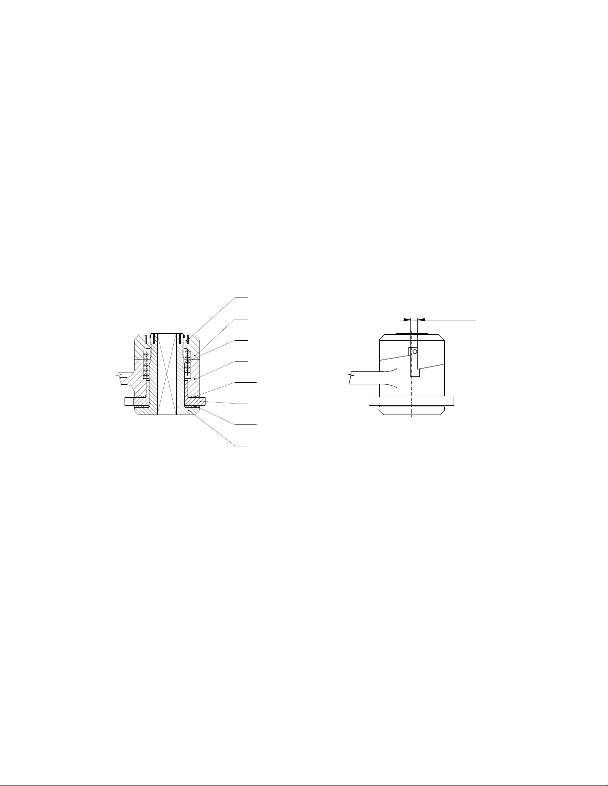
11.2.1 Brake disassembly (fig. 6) ........................................................................................14
11.2.2 Brake assembly and adjusting (fig. 6 and 7) .............................................................14
11.3 GENERAL INSTRUCTION...........................................................................................14
11.4 CHECK UP...................................................................................................................15
11.5 REPAIR........................................................................................................................15
11.6 TEST............................................................................................................................15
12 PUTTING OUT OF OPERASTION – LIQUIDATION .......................................................15
13 RELATED DOCUMENTATION .......................................................................................15
14 FINAL REQUIREMENTS OF THE PRODUCER TO THE CUSTOMER ..........................15
EC DECLARATION OF CONFORMITY ...............................................................................16

3
1 DEFINITION
! HAZARD
Hazard: it adverts to an imminent hazardous situation, which will inflict
death or serious injury, if the operation personnel will not avoid it.
! WARNING
Warning: it adverts to a possible hazardous situation, which could inflict
death or serious injury, if the operation personnel will not avoid it.
! NOTICE
Notice: it adverts to a possible hazardous situation, which could inflict
any minor or slight injury, if the operation personnel will not avoid it. The
notice can warn against hazardous practices as well.
Load capacity (Q): is the maximum permitted weight (working load limit) of a load on the
jack head, by which the jack is possible to be loaded when handling on conditions
specified in this Operation Manual.
Load capacity (Q1): is the maximum permitted weight (working load limit) of a load on the
rest, by which the jack is possible to be loaded when handling on conditions specified in
this Operation Manual.
2 DEVICE UR OSE
2.1 The 15-00, 15-00-VK, 15-00-RK, 15-00-VK-RK, 15-01,15-01-VK, 15-01-RK, 15-01-VK-
RK and Z 23 rack jack types with load capacities 2,5t, 5t, 10t, 16t and 20t and type HZ
lifting capacity 5t (hereinafter referred to as jack) is designed entirely for manual raising,
lowering and pushing of free loads in the workplace. The load weight when raising does
not have to exceed specified permitted load capacity.
2.2 The jack by its design meets requirements provided by Directive 98/37/EC of the
European Parliament and of the Council as amended by the Czech technical regulation –
ministerial order No. 24/2003 of the Collection of Laws as amended as well as
requirements of the ČSN EN ISO 12100-1, ČSN EN ISO 12100-2, ČSN EN 1050 and ČSN
EN 1494 harmonized technical standards.
2.3 The jack by its design meets requirements specified for the group I of devices
(mine) category M2 according to the Directive 94/9/EC of the European Parliament and of
the Council as amended by the Czech technical regulation – ministerial order No. 23/2003
of the Collection of Laws as amended as well as requirements of the ČSN EN 13463-1
harmonized technical standard and complies with the conditions for use in „hazardous
atmospheric conditions 2“ environment according to the ČSN EN 1127-2 standard with
the limitation according to the national regulation – CBM (Czech Bureau of Mine)
regulation No.22/89 of Collection of Law § 232 section (1) c) up to 1,5% of mine gas
accumulation.
2.4 The jack by its design meets requirements specified for the group II of devices (non-
mine) category 2 and 3 according to the Directive 94/9/EC of the European Parliament and
of the Council as amended by the Czech technical regulation – ministerial order No.
23/2003 of the Collection of Laws as amended as well as requirements of the ČSN EN
13463-1 harmonized technical standard and complies with the conditions for use in „zone
1 and zone 21“, „zone 2 and zone 22“ environments according to the ČSN EN 1127-1
standard.
Note: 2.3 and 2.4 articles apply for jack designed for use in the environment with explosion
hazard.

4
3 SECURITY RINCI LES
3.1 SECURITY RINCI LES OVERVIEW
A hazard exists when handling loads especially in the event that the jack is not use in the
right way or is badly maintained. Whereas as a result an accident or severe injury could
happen, it is necessary to observe the special security measures when handling,
assembling, maintaining and checking the jack.
! WARNING
ALWAYS ensure the load against drop (i.e. by a stand or jack block), if you are going to
work under it.
NEVER burden the jack more than is the load capacity indicated on the jack.
NEVER jack up persons.
ALWAYS warn persons in surroundings before starting work.
ALWAYS read the operation manual and security instructions.
Bear in mind that the operation staff i
s responsible for faultless technique of raising loads.
Hence verify all national directives, regulations and standards whether they contain other
information on safety work with your jack.
3.2. SECURITY RINCI LES
! WARNING
3.2.1 rior to use
ALWAYS ensure the jack would be operated by physically fit, qualified and instructed
persons older than 18 years, familiarized with the operation manual and
trained in security of work and mode of operation.
ALWAYS check up the jack every day before starting work according to section 8.2. (1)
„Daily inspection“.
ALWAYS make sure that the lift is adequate for intended work.
ALWAYS respect the jack is on firm foundation.
NEVER jack up loads well set or of unknown weight.
NEVER push with the jack without knowledge of expansion forces.
NEVER use the defective or outworn jack.
NEVER use the jack without visible load capacity marking on the jack.
NEVER use the jack marked with the label „OUT OF O ERATION“.
ALWAYS consult the producer or his authorized representative any application of the
jack in nonstandard or extreme environment.
3.2.2 When in use
ALWAYS attend to the jack would stay vertically when jacking up.
ALWAYS make sure the load is fitly put on the jack.
ALWAYS pay increased attention, if the jack is drawn up to maximum position.

5
ALWAYS work with the jack only with manpower.
ALWAYS when jacking up loads with a weight oncoming safe working load of the hoist
we recommend the operation would be ensured by two persons owing to
magnitude of actuating forces.
NEVER use the jack for anchoring of loads.
NEVER allow the load would give rise to impacts or vibrations.
3.2.3 Risk analysis
The possible risks analysis in light of design, operation and environment of the jack
appointment is presented in freestanding document „Risk analysis“. It is possible to require
the document in service centers.
3.2.4 Maintenance
ALWAYS make possible to competent persons to carry out the regular inspection of the
jack.
ALWAYS ensure slipping parts would be sufficiently greased.
At maintenance only such interventions can be done that will be in accordance with
producer’s requirements stated in the chapter 11 of this OM.
IT IS NOT ERMITTED to carry out repairs and maintenance in other manner than
specified by the producer. It concerns namely the forbiddance of using of unoriginal spare
parts or carrying out changes on the product without the approval of the producer.
4 ACKING, STORAGE AND HANDLING
4.1 ACKING
4.1.1 Jacks are supplied in assembled state in bulk in transport cases.
4.1.2 The following accompanying documentation is a part of the delivery:
a) Operation Manual
b) EC Declaration of Conformity
c) Quality and Completeness Certificates and Guarantee Certificate.
c1) Guarantee period is stated in the Guarantee Certificate.
c2) The guarantee does not apply to defects caused by infringement of the
instructions stated in the Operation Manual and defects arisen by improper
using and unskilled action.
c3) The guarantee does not apply as well to changes on the product or using of
unoriginal spare parts without the approval of the producer.
c4) Reclaiming of product defects is carried out according to applicable
provisions of commercial code eventually as amended.
d) List of service centers.
4.2 STORAGE
Store jacks in dry and clean stores void of chemical impacts and noxious fumes.
(1) Wipe away all dust, water and impurities from the jack.
(2) Grease the rack of the jack.
(3) Put the jack in a dry place.
(4) In next using follow instructions in the article 8.1.4 „Jack occasionally used“.

6
4.3 HANDLING
During transportation and handling, observe technical regulations and standards in force
for work with heavy loads.
5 MAIN S ECIFICATIONS
Load
capacity
(t)
Type
Q Q
1
Actuating
force on
crank
(N)
Range of
Operating
temperature
Weight
(kg)
15-00
15-00-RK
15-00-VK
15-00-VK-RK
2,5 1,75
380 15
15-00
15-00-RK
15-00-VK
15-00-VK-RK
5 3,5 550 22
HZ 5 3,5 550
1)
330
2)
23
15-01
15-01-RK
15-01-VK
15-01-VK-RK
10 7 540 38
15-01 16 11,2
730 65
Z 23 20 14 800
-20°C
till
+50°C
90
1) Handle in position “crank”
2) Handle in position “lever”
5.1 MECHANICAL DEVICE
Safety and working life of the jack is guaranteed if it works in accordance with specified
classification.
The jack is designed for class 1Bm according to the FEM 9.511 regulation – see table 5.1.
(it corresponds to mechanism classification M3 according to the ISO 4301/1).
Average daily operating time is specified in the load diagram.
Tab. 5.1 MECHANICAL CLASSIFICATION
Load diagram
(load distribution)
Definition Load coefficient Average daily
operating time (h)
1
(light)
Jacks usually being subject
to the low load and only in
special cases to the
maximum load.
k≤0,50 1 - 2
2
(mean)
Jacks usually being subject
to the low load, but quite
often to the maximum load.
0,50< k ≤ 0,63 0,5 - 1
3
(heavy)
Jacks usually being subject
to the mean load, but
frequently to the maximum
load.
0,63< k ≤ 0,80 0,25 – 0,5
4
(very heavy)
Jacks usually being subject
to the maximum load or load
approximating to the
maximum.
0,80< k ≤ 1,00 0,12 – 0,25
70%
Q1
100%
Q
Fig. 1

7
Load diagram Load diagram Load diagram Load diagram
1 2 3 4
Percentage of operating time
5.2. MATERIAL AND FINISH
5.2.1 All parts of the jack are manufactured from steel and cast iron, the brake liners from
hardened woven fabric.
5.2.2. Materials susceptible to a creation of an incentive spar within the meaning of the
Annex No.2 Article 1.3.1 to the ministerial order No. 23/2003 of the Collection of
Law and the ČSN EN 1127-2 article 6.4.4 and ČSN EN 13463-1 article 8.1
harmonized technical standards are not used.
5.2.3. Materials with dangerous effects of static electricity within the meaning of the ČSN
EN 1127-2 article 6.4.7, ČSN EN 1127-1 article 6.4.7, ČSN EN 13463-1 article 7.4.3
and ČSN 33 2030 are not used in the jack.
5.2.4 The jack does not exceed the noise value specified in the Annex No.2 article 1.7.4
letter f of the ministerial order No. 24/2003 of the Collection of Law (EP and RE
directive No. 98/37/EC).
Note: Articles 5.2.2 and 5.2.3 apply for jack finish to environment with explosion risk.
5.3 DATA ON THE RODUCT
Each product is equipped with the label with specified data as follows:
Standard finish: Finish to environment with explosion risk:
Mark of the producer Mark of the producer
Address of the producer Address of the producer
Product type Product type
Load capacity Load capacity
Serial number Serial number
Production year Production year
CE marking CE marking
Protection type symbol (I M2 for group I , II 2G for
group II)
6 JACK O ERATION
! WARNING
ALWAYS before installation check up thoroughly whether the jack is not damaged.
ALWAYS safeguard the jack against drop at pushing or spreading out of loads (i.e. in
horizontal direction). A drop can take place when shifting the load and thereby
unloading and releasing the jack. Every such handling is necessary to be
appreciated individually in terms of safety.
NEVER the load weight or resultant pushing force on the head must not exceed the safe
working load of the jack.

8
1
2
Lowering
position
Lifting
position
Neutral
position
! NOTICE
The jack safe working load on the rest is decreased by 30%.
6.1 JACK O ERATION INSTRUCTIONS
The jack is operated by the crank. Raising or lowering the load can be cut off in any lifting
height. A lowering brake and pawl system with forced mesh in the jack crank safeguard
the stability of the load position.
! NOTICE
At actuating force greater than 400N (it means when handling with the jack at the
safe load limit) the jack must be operated by 2 persons at least.
6.2 REST ADJUSTMENT
(only types 15-00-VK, 15-01-VK, 15-00-VK-RK, 15-01-
VK-RK).
Position of the adjustable rest can be changed in the
range given by a number of mounting positions on the
jack bar (only types 15-00-VK, 15-01-VK, 15-00-VK-RK,
15-01-VK-RK).
After removal of the breaking piece (2) and shifting of
the rest in the direction indicated by an arrow, fastening
pin (1) . 2 get loose in the jack bar and rest can be put
out. Carry out rest fitting-on to other position by
opposite procedure.
6.3 RATCHET CRANK O ERATION AND
THE RATCHET CRANK-LEVER
(only types 15-00-RK, 15-01-RK, 15-00-VK-RK, 15-01-VK-RK a HZ ).
6.3.1 Raising or lowering
Before raising hitch up the
changeover lever and set on the
mark of raising – up-arrow (see fig.3).
Carry out the raising by oscillating
(eventually rotation) motion of the
ratchet crank.
At the beginning of the raising before
the loading of the rack jack will take
place, hold the knurled nut so that it
would not be carried away by the
crank at its backwards motion.
Before lowering the load, shift the changeover lever to the position on the lowering mark –
down arrow (see fig.3). Lower down the load by oscillating (eventually rotation) motion of
the ratchet crank.
Make sure at each change of the position of the changeover lever, whether the lever gets
fitly to the socket in the ratchet crank.
First motion of the ratchet crank after reversing (after shifting of the changeover lever) is
slightly blocked. This state arises by an influence of stronger follow-through of the brake
Fig.2
fig.3

9
200
R = 525
70
360
3,5t
83
5t
R = 300
Poloha KLIKA (R )
Poloha PÁKA (R )
Poloha TRANSPORT
k
p
765
225
Poj stka prot přetížení
p
k
fig.4
Position transport
Overloading
safety
Position lever
Position crank
namely at manipulation with heavier loads. In this case release the brake by more point-
blank motion, thereby you will coincidently release the ratchet crank.
6.3.2 Ratchet crank-lever
The manipulation with the ratchet crank-lever during the lifting and lowering of loads is
performed in the same way as is stated in article 6.3.1 and 6.3.2.
The ratchet crank is changed to an extended lever by folding the crank-lever handle by 90
0
(into the lever position - see fig.4). We use this position for decreasing the control force
during the manipulation with loads that are close to the nominal lifting capacity of the lifter.
The ratchet crank-lever is equipped with a safety shear pin against overloading (see fig.4)
If the shear pin is sheared during the manipulation with a load, it is still possible to lower
the load even if the shear pin is sheared (after moving the reverse lever to the lowering
position).
! WARNING
NEVER extend the lever’s arm with a pipe or by any other method. The lever might get
damaged
! NOTICE
The ratchet crank and also the ratchet crank-lever is interchangeable with a standard
crank of correspondent type of jack. In case of replacement of the standard crank with the
RK 300 ratchet crank at jack with load capacity 5t it is necessary before assembling to put
on the square shank of the crank pinion the spacing tube – it is a part of delivery of the RK
300 ratchet crank– for safeguarding the correct position of the ratchet crank on the jack.
6.4 BEARING SURFACE CHECK-U /floor, rough ground/
! NOTICE
ALWAYS make sure that the bearing surface is sufficiently firm to hold tightly supposed
loading for all time of handling. The installation must not be carried out on the

10
POUŽITÍ VE VODOROVNÉ POLOZE
F xace pomocí otvoru v patce
Abb. 5
A LICATION IN HOR
IZONTAL OSITION
Fastening by the help of the opening in foot
surface where it is not possible to determine the load-bearing capacity or that is
instable.
ALWAYS the operation personnel are responsible for the set-up!
6.5 TEST RIOR TO USE
! NOTICE
(1) At first read again the previous articles of this manual and make sure that all steps
were correctly done and all parts are safety mounted.
(2) Visually check the jack and bearing surface whether they are without defects.
(3) Put to proof the jack function by the motion of the crank without loading.
(4) Carry out several jacking up and lowering with the suitable load (10% till 50% of the
load capacity). At the same time verify, whether the jack will hold firmly the load without
slipping when lowering and stopping.
7 O ERATION
7.1 A LICATION OF THE JACK
7.1.1 The jack is multifunctional equipment destined for manual jacking up, lowering,
pushing and spreading of subjects in the workplace determined by the user. It can
be used not only in a current environment, but also in environments with explosion
risk in the event that there is the symbol of the protection type marked on the label –
see articles 2.3, 2.4 and 5.3 of this OM.
The lifters type HZ have
an opening in the foot
which simplifies work
when pushing apart
objects above head
height. The lifter’s foot
can be easily attached in
the required position by
using a screw for
example, without the
need to use a helper.
(fig. 5)
7.1.2 By reason that the work with heavy loads can constitute unexpected hazard it is
necessary to follow all „Security principles“ according to the chapter 3 of this OM.
7.2 SAFETY WORK ENVIRONMENT
! Warning
(1) The operating personnel must be demonstrably acquainted with this Operation Manual;
they must adhere to valid security and hygienic regulations and must be qualified for
operation of this equipment.
(2) When working with the jack the operation staff must be equipped with gloves and
appropriate footwear.
(3) When operating by more persons always one worker must be determined who is
trained in safety at work and is responsible for jack handling.
fig.5

11
(4) Before starting the work, the operation staff must check up whether all work area is
safety and whether there is the possibility of eventual escape from the environment of
jeopardy.
8 CHECK-U ON THE JACK
8.1 INS ECTION
8.1.1 Inspections types
(1) Introductory inspection: it precedes first use. The responsible competent person must
check up all new or repaired jacks to ensure the qualified fulfilment of requirements of
this OM.
(2) The jack inspections carried out regularly are generally divided to two groups
according to inspections intervals. Intervals depend on the state of critical parts of the
jack and rate of wear, damage or malfunction. Two main groups are here marked as
daily and regular ones. The appropriate intervals are defined as follows:
(a) Daily inspection: visual check up carried out by the operation staff determined by the
user that is made at the beginning of each use.
(b) Regular inspection: visual check up carried out by the competent person determined
by the user.
1) Current operation – once a year,
2) Heavy operation – every six month,
3) Special or occasional operation – according to recommendations of the competent
person at first use and according to the order of qualified employees (maintenance
workers).
8.1.2 Daily inspection
Check up at parts recommended in the section 8.2(1) „Daily inspection“, whether the jacks
are not damaged nor have no defect. Carry out this inspection also during operation in the
interval between regular inspections. Qualified employees will determine, whether any
defect or damage can constitute a hazard and whether the detailed inspection is
necessary.
8.1.3 Regular inspection
Carry out overall inspections of the jack in the form of recommended regular inspections.
The recommended regular inspection stated in the section 8.2(2) must be performed under
the supervision of the competent persons who will determine, whether the jack is
necessary to be taken to parts. These inspections comprise also requirements of the daily
inspection.
8.1.4 Jack occasionally used
(1) Submit the jack not being in operation for a period of one month or longer but less than
a year to inspection complying with requirements in the section 8.1.2 before follow-up
putting it into operation.
(2) Submit he jack not being in operation for a period of one year to inspection complying
with requirements in the section 8.1.3 before follow-up putting it into operation.
8.1.5 Report on inspection
Keep the record of performed tests, inspections and maintenances of jacks every time.
Carry out dating reports on inspections in intervals specified in the section 8.1.1 (2)(b) and
keep them in the place specified by the user.

12
The person responsible for safety and determined by the user must be advised of defects
detected by the inspection or recorded during the operation.
8.2 INS ECTION ROCEDURE
(1) Daily inspection (carried out by operating staff or person responsible)
art Inspection method
Limit / criteria for
putting-out of
operation
Remedy
1. Jack function Visually,
aurally
The jack goes
hardly, stammers,
emits noise etc.
To clean up and
grease the jack. If
the defect will not
be removed, get the
jack repaired.
2. Pawls function Visual inspection
when jacking up
Pawls do not snap
behind dents of the
ratchet.
To clean up,
grease, eventually
change the spring.
3. Fixative parts
Visual inspection of
all screws, nuts,
rivets etc.
Faulty or missing
parts;
Released parts
Replace by new
ones;
To retighten
released parts
(2) Regular inspection (carried out by the competent person)
art
Inspection
method
Limit / criteria for
putting-out of
operation
Remedy
1. Fixative parts
Visual inspection
of all screws, nuts,
rivets etc.
Faulty or missing
parts;
Released parts
Replace by new
ones;
To retighten
released parts
2. All parts Visual inspection Outworn or
damaged parts;
Fouled and
ungreased parts
Replace by new
ones;
To take to parts,
clean up, grease
and again assemble
3. Label – marking of
load capacity on the
jack
Visual inspection Load capacity is not
readable
To repair or replace
by new one
4. Brake Jack up and lower
the load with
weight equal
approximately to
the load capacity
of the jack
When interrupting
jacking up the brake
must hold firmly the
load in each
position during
raising and lowering
If it will not be so,
ask for repair and
adjusting of the
brake

13
9 TROUBLE-SHOOTING
Situation Cause of trouble Remedy
1. Jack does not hold firmly
the load.
Brake slipping. Brake adjusting or repair
according to the chapter
„Maintenance“.
2. Jack jacks up heavily or
does not raise the load.
(1) Jack is overloaded.
(2) Damaged geared
transmission.
(1) Lower the load weight
to the value of the safe
working load.
(2) Repair of the jack
3. Jack emits the special
noise.
Insufficiently greased
geared transmission.
Carry out the lubrication of
the geared transmissions
by grease.
4. Characteristic sound is
not heard when snapping
the pawls to dents of
ratchet.
Malfunction of pawls.
Rust, impurities, broken
spring.
Clean up, replace the
spring.
10 GREASING
10.1 GENERALLY
Before application of the grease remove old grease, clean up components with grease
solvent and apply new grease. Use grease specified by the producer.
Lifters type HZ are equipped with a lubrication plug on the cover of the gear transfer. We
recommend regular lubrication of the gear mechanism at least once every 6 months.
10.2 JACK MECHANISM
Throw up the unloaded jack to the maximum position. Grease with PM-A2 vaseline or its
equivalent the ridge bar and lower down the jack.
Lifters type Rack lifter are to be lubricated with a lubrication press through the lubrication
plug.
Grease all slipping or moveable surfaces on the crank of the jack.
! NOTICE
Imperfect maintenance and insufficient greasing can cause a serious accident.
ALWAYS grease more often in corrosive environment (salt water, oceanic climate,
acids etc.) than in ordinary circumstances.
11 MAINTENANCE
11.1 SECURITY RINCI LES
! Warning
Only qualified persons (service organizations), trained in safety and maintenance of
the jacks, can carry out maintenance and professional inspections.
ALWAYS use entirely components supplied by the producer.

14
It is not permitted to carry out repairs and maintenance in other way than
specified by the producer. It means namely the forbiddance of using unoriginal
spare parts or carrying out of changes on the product without the approval of the
producer.
ALWAYS test jack function after carrying out the maintenance.
ALWAYS mark disabled or repaired jack with appropriate inscription (i.e. „OUT OF
O ERATION“).
NEVER carry out maintenance if there is the load on the jack.
NEVER work with the jack that is under repair!
11.2 RE LACEMENT OF BRAKE INSERTS AND BRAKE ADJUSTING
11.2.1 Brake disassembly (fig. 6)
Demount the (crank or crank-lever) from the jack. Unbolt safety screws (6) and
consequently the nut (5). Take out the spring (4) and crank arm (7). Take out from the hub
(1) the ratchet (3) with brake insert (2A), take off the brake insert (2B), and replace both
brake inserts (2A) (2B).
Fig. 6 Fig. 7
11.2.2 Brake assembly and adjusting (figures 6 and 7)
Proceed in the opposite way when assembling. Slip over the hub (1) the friction insert
(2B); ratchet (3) and second friction insert (2A). Set it in the crank arm (7), slide on the
spring (4) and screw on the nut (5). Tighten the nut so that the clearance in the dent is
from 4 to 6 mm (see fig. 5) and screw down the screws (6).
11.3 GENERAL INSTRUCTIONS
Following instructions give general important information on disassembly, check up, repair
and assembly. If the jack was dismounted from any reason act upon the instructions as
follows.
1. Perform maintenance in clean environment.
2. NEVER disassemble the jack more than it is necessary to carrying out the needful
repair.
3. NEVER use excessive power when dismantling parts.
4. NEVER use heat (fire) as the mean when dismantling parts, if the parts are destined for
next use.
5. Keep the workplace clean and without foreign materials that could get into bearings
and other movable parts.
7
6
5
4
2A
3
2B
1
4 till 6 m m

15
6. If you squeeze the part in vice, use always the appropriate pads for protection of parts
surfaces.
11.4 CHECK U
Check up, whether all disassembled parts are suitable for next use.
1. Check up, whether no parts are worn out and have no chutes or fissures.
2. Check up, whether threaded parts have not the damaged thread.
11.5 RE AIR
Outworn or damaged parts must be replaced.
Remove little burrs and scratches or other minor surface defects and flatten out with fine
grinder or abrasive cloth.
11.6 TEST
The load test must be performed at all repaired jacks by qualified person with the load
exceeding the load capacity by 10% for verification of function and brake of the jack.
12 UTTING OUT OF O ERATION – LIQUIDATION
The jack do not contain any noxious agents, its parts are from steel and cast iron. Hand
over the jack after putting out of operation to the firm dealing with liquidation of waste
metal.
13 RELATED DOCUMENTATION
13.1 EC declaration of conformity
13.2 The Operation Manual was elaborated in accordance with following technical regulations,
technical standards and national regulations:
• Ministerial order No.24/2003 of the Collection of Law as amended (EP and Council directive
98/37/EC)
• Ministerial order No.23/2003 of the Collection of Law as amended (EP and Council directive
94/9/EC)
• ČSN EN ISO 12100 - 1
• ČSN EN ISO 12100 - 2
• ČSN EN 1494
• ČSN EN 1050
• ČSN EN 1127 - 2
• ČSN EN 1127 - 1
• ČSN EN 13463 - 1
• Regulation of CBM (Czech Bureau of Mine) No.22/89 of the Collection of Law
• ČSN 33 2030.
14 FINAL REQUIREMENTS OF THE RODUCER TO THE
CUSTOMER
Any changes of the product, eventually usage of unoriginal spare parts can be
realized only based on the approval of the producer.
When not observing this condition the producer does not guarantee safety of his
product. In this case, any producer’s guarantees do not apply to the product.

16
EC Declaration
of conformity
Manufacturer
BRANO a.s.
747 41 Hradec nad Moravicí, Opavská 1000
The Czech Republic
ID No.: 45193363 TIN: CZ45193363
We declare under our sole responsibility that the product
Name:
Type:
arameters:
Rack jack
15-00; 15-01; Z23
Load capacity 2,5t; 5t; 10t; 16t; 20t
Description and purpose of use:
Jacking equipment destined entirely for underposable raising and
lowering of free loads at normal atmospheric conditions in the workplace
when observing the specified maximum load capacity.
Is in conformity with the following directives and standards:
MO CR No. 24/2003 of Coll.of Law, RE directive No. 98/37/EC,
ČSN EN ISO 12100-1:2004(EN ISO 12100-1:2003), ČSN EN ISO 12100-
2:2004(EN ISO 12100-2:2003), ČSN EN1050:2001(EN1050:1996), ČSN EN 1494
The following authorized body had a share in conformity
assessment
:
-----------
Hradec nad Moravicí 1.9.2004 Ing. Alena Šimečková Ing.Zdeněk Pavlíček
………………………………………………………………………………………………………………….
Place Date Director of SBU ZZ Manager of Q SBU ZZ
This manual suits for next models
14
Table of contents
Other Brano Jack manuals
Popular Jack manuals by other brands

K Tool International
K Tool International KTI-63500A owner's manual

Enerpac
Enerpac PT Series instruction sheet

Mohawk
Mohawk RJ-50-AH Series Installation, operation, maintenance, parts

BIG RED JACKS
BIG RED JACKS T90203 owner's manual

Napa
Napa 791-7330 B Operating manual & parts list

TQB
TQB 2906T Maintenance Guide

Napa
Napa Carlyle Tools 791-6445 operating manual

Pittsburgh Automotive
Pittsburgh Automotive 64542 Owner's manual & safety instructions

Tronair
Tronair 02-1036C0111 Operation & service manual

Cattini Oleopneumatica
Cattini Oleopneumatica YAK 215/N Operating and maintenance manual

Arcan
Arcan XL20 operating instructions

VEVOR
VEVOR TJP-5002S-B quick start guide