Branson Sonifier SLPt User manual

Sonifier® Cell Disruptor
Model SLPt
User’s Manual
EDP 100-214-252
Rev. A
BRANSON Ultrasonics Corporation
41 Eagle Road
Danbury, Connecticut 06813-1961 U.S.A.
(203) 796-0400
DOC EXPIRES 12PM 9/16/2007. Article or Material must comply with the requirements
stipulated by RoHS in its current version of 1/27/03

100-214-252 Rev. A April 2004
Manual Change Information
At Branson, we strive to maintain our position as the leader in ultrasonics plastics joining,
cleaning and related technologies by continually improving the designs, circuits and com-
ponents in our equipment. These improvements are incorporated as soon as they are devel-
oped and thoroughly tested.
Information concerning any improvements will be added to the appropriate technical doc-
umentation at its next revision and printing. Therefore, when requesting service assistance
for specific units, note the Release information found on the cover of this document, and
refer to the printing date which appears in the lower right corner of this page.
Patents and Copyright
Copyright ©2003 by Branson Ultrasonics Corporation, Danbury, Connecticut, U.S.A.
All rights reserved.
Manual part number: EDP 100-214-252, Initial Release printed August 2003.
Branson Ultrasonics Corporation equipment is manufactured under one or more of the fol-
lowing U. S. Patents:
4,249,986; 4,315,181; 4,363,992; 4,551,690; 4,651,043; 4,786,356; 4,973,876; 5,095,188;
5,435,863.
Note: Sonifier®is a registered trademark of Branson Ultrasonics Corporation, Danbury,
Connecticut, U.S.A. Other trademarks and service marks respectfully mentioned herein are
held by their respective owners.
DOC EXPIRES 12PM 9/16/2007. Article or Material must comply with the requirements
stipulated by RoHS in its current version of 1/27/03

Sonifier®Cell Disruptor
Model SLPt
User’s Manual
EDP 100-214-252
Initial Release
Forward
Congratulations on your choice of a Branson Ultrasonics Corporation system!
The Branson Digital Sonifier®systemis the newest generation ofproduct using this sophis-
ticated technology for a variety of customer applications. This manual should be kept with
the system.
Thank you for choosing a Branson product!
Introduction to this manual
This manual is arranged into seven structured chapters which will help you find the infor-
mation you may need to know to safely handle, install, set up, program, operate, and/or
maintain this product. Additional information is provided in several Appendix chapters.
In the event you require additional assistance or information, please contact our Product
Support department (see ’How to Contact Branson’ op pagina 5 for information on how to
contact us) or your local Branson representative.
DOC EXPIRES 12PM 9/16/2007. Article or Material must comply with the requirements
stipulated by RoHS in its current version of 1/27/03

100-214-252 Rev. A
For Your Notes
DOC EXPIRES 12PM 9/16/2007. Article or Material must comply with the requirements
stipulated by RoHS in its current version of 1/27/03

SLPt Cell Disruptor
User Manual
100-214-252 Rev. A -1
Chapter 1: Safety and Support
1.1 Safety Considerations - - - - - - - - - - - - - - - - - - - - - - - - - -1 - 1
1.2 General Precautions - - - - - - - - - - - - - - - - - - - - - - - - - - -1 - 2
1.2.1 Intended Use of the System - - - - - - - - - - - - - - - - - - - - - -1 - 2
1.2.2 Safety Measures and Guards- - - - - - - - - - - - - - - - - - - - - -1 - 2
1.2.3 Safe Operation- - - - - - - - - - - - - - - - - - - - - - - - - - - - -1 - 3
1.2.4 Setting Up the Workplace- - - - - - - - - - - - - - - - - - - - - - - -1 - 3
1.3 Regulatory Compliance - - - - - - - - - - - - - - - - - - - - - - - - - -1 - 4
1.4 Warranty - - - - - - - - - - - - - - - - - - - - - - - - - - - - - - - - -1 - 5
1.5 How to Contact Branson - - - - - - - - - - - - - - - - - - - - - - - - -1 - 6
1.5.1 Before Calling Branson for Assistance - - - - - - - - - - - - - - - - -1 - 6
Chapter 2: Introduction to the SLPt Cell Disruptor
2.1 Overview of SLPt Cell Disruptor - - - - - - - - - - - - - - - - - - - - -2 - 1
2.2 Controls and Commands - - - - - - - - - - - - - - - - - - - - - - - - -2 - 2
2.2.1 SLPt Cell Disruptor Keypad/Display Description- - - - - - - - - - - - -2 - 4
2.2.2 Back Panel Connections - - - - - - - - - - - - - - - - - - - - - - - -2 - 5
2.3 System Features - - - - - - - - - - - - - - - - - - - - - - - - - - - - -2 - 6
Chapter 3: Delivery and Handling
3.1 Delivery and Handling - - - - - - - - - - - - - - - - - - - - - - - - - -3 - 1
Chapter 4: Installation and Setup
4.1 Installation Checklist - - - - - - - - - - - - - - - - - - - - - - - - - - -4 - 1
4.2 System Block Diagram - - - - - - - - - - - - - - - - - - - - - - - - - -4 - 2
4.3 System Component Description - - - - - - - - - - - - - - - - - - - - -4 - 2
4.3.1 Standard Components - - - - - - - - - - - - - - - - - - - - - - - - -4 - 2
4.3.2 Tools- - - - - - - - - - - - - - - - - - - - - - - - - - - - - - - - - -4 - 3
4.4 Assembling the Equipment - - - - - - - - - - - - - - - - - - - - - - - -4 - 6
4.4.1 Setup Procedure - - - - - - - - - - - - - - - - - - - - - - - - - - - -4 - 6
4.4.2 Connecting Microtips, and Converters - - - - - - - - - - - - - - - - -4 - 7
4.5 Input Power Requirements - - - - - - - - - - - - - - - - - - - - - - - -4 - 8
4.6 Electrical Connections to Equipment- - - - - - - - - - - - - - - - - - -4 - 8
Table of Contents
DOC EXPIRES 12PM 9/16/2007. Article or Material must comply with the requirements
stipulated by RoHS in its current version of 1/27/03

-2 100-214-252 Rev. A
4.6.1 Power Cord - - - - - - - - - - - - - - - - - - - - - - - - - - - - - -4 - 8
4.6.2 User I/O Connection - - - - - - - - - - - - - - - - - - - - - - - - - -4 - 9
4.7 Guards and Safety Equipment - - - - - - - - - - - - - - - - - - - - - -4 - 9
4.8 Ultrasonic Test - - - - - - - - - - - - - - - - - - - - - - - - - - - - - 4 - 10
Chapter 5: Technical Specifications
5.1 Technical Specifications - - - - - - - - - - - - - - - - - - - - - - - - -5 - 1
5.2 Physical Description - - - - - - - - - - - - - - - - - - - - - - - - - - -5 - 2
5.3 System Performance Benchmark- - - - - - - - - - - - - - - - - - - - -5 - 3
Chapter 6: Operation
6.1 Front Panel Controls - - - - - - - - - - - - - - - - - - - - - - - - - - -6 - 1
6.1.1 Power Switch - - - - - - - - - - - - - - - - - - - - - - - - - - - - -6 - 1
6.1.2 Membrane Keypad - - - - - - - - - - - - - - - - - - - - - - - - - - -6 - 2
6.2 Rear Inputs and Connections- - - - - - - - - - - - - - - - - - - - - - -6 - 4
6.3 System Modes - - - - - - - - - - - - - - - - - - - - - - - - - - - - - -6 - 4
6.3.1 Menu Navigation - - - - - - - - - - - - - - - - - - - - - - - - - - - -6 - 4
6.3.2 Configuration Menu - - - - - - - - - - - - - - - - - - - - - - - - - -6 - 4
6.3.3 Control Menu- - - - - - - - - - - - - - - - - - - - - - - - - - - - - -6 - 5
6.4 Operational Sequence - - - - - - - - - - - - - - - - - - - - - - - - - -6 - 7
6.4.1 SLPt in Continuous Mode- - - - - - - - - - - - - - - - - - - - - - - -6 - 7
6.4.2 SLPt in Time Mode (Either Low, min/sec or High, hr/min) - - - - - - - -6 - 8
6.4.3 SLPt in Time Mode with Pulse (Either Low, min/sec or High, hr/min)- - -6 - 8
6.5 Alarms - - - - - - - - - - - - - - - - - - - - - - - - - - - - - - - - - -6 - 9
Chapter 7: Maintenance
7.1 Maintenance and Troubleshooting - - - - - - - - - - - - - - - - - - - -7 - 1
7.2 Reconditioning the Converter/Tool Interface - - - - - - - - - - - - - - -7 - 2
7.2.1 Refacing the Mating Surfaces- - - - - - - - - - - - - - - - - - - - - -7 - 3
7.3 Troubleshooting Charts- - - - - - - - - - - - - - - - - - - - - - - - - -7 - 3
7.4 Interconnect Diagram - - - - - - - - - - - - - - - - - - - - - - - - - - -7 - 6
DOC EXPIRES 12PM 9/16/2007. Article or Material must comply with the requirements
stipulated by RoHS in its current version of 1/27/03

SLPt Cell Disruptor Chapter 1: Safety and Support
User Manual Safety Considerations
100-214-252 Rev. A 1-1
Chapter 1: Safety and Support
1.1 Safety Considerations - - - - - - - - - - - - - - - - - - - - - -1 - 1
1.2 General Precautions - - - - - - - - - - - - - - - - - - - - - - -1 - 2
1.2.1 Intended Use of the System - - - - - - - - - - - - - - - - - -1 - 2
1.2.2 Safety Measures and Guards- - - - - - - - - - - - - - - - - -1 - 2
1.2.3 Safe Operation- - - - - - - - - - - - - - - - - - - - - - - - -1 - 3
1.2.4 Setting Up the Workplace- - - - - - - - - - - - - - - - - - - -1 - 3
1.3 Regulatory Compliance - - - - - - - - - - - - - - - - - - - - - -1 - 4
1.4 Warranty - - - - - - - - - - - - - - - - - - - - - - - - - - - - -1 - 5
1.5 How to Contact Branson - - - - - - - - - - - - - - - - - - - - -1 - 6
1.5.1 Before Calling Branson for Assistance - - - - - - - - - - - - -1 - 6
1.1 Safety Considerations
CAUTION
!Observe the following safety considerations when operating the Sonifier® SLPt Cell Disrup-
tor®:
• Make sure that the equipment is properly grounded. DO NOT operate if it is not.
• The unit is equipped with a three-conductor cord and three-prong grounding-type plug, and must be
plugged into a three-prong grounding-type wall receptacle. DO NOT under any circumstances remove
the power cord ground prong.
•DO NOT operate the equipment with the cover removed. High voltage is present within the equipment
when connected to plant wiring.
•DO NOT turn on the ultrasonics without the converter and horn attached.
•DO NOT touch the horn or tip when ultrasonics are active. When handling, removing, or attaching a horn
or tip, be sure that the ON/OFF switch is set to OFF. Touching the horn or tip while the unit is on can
result in serious personal injury.
•DO NOT allow the horn or microtip to contact lab stands, beakers, test tubes or similar objects. Microtip
failure may result. Breakage of glassware may result in the loss of a specimen.
•DO NOT operate the equipment at more than 70% amplitude when using a microtip.
• Appropriate eye protection should be worn to prevent possible splash injury.
DOC EXPIRES 12PM 9/16/2007. Article or Material must comply with the requirements
stipulated by RoHS in its current version of 1/27/03

Chapter 1: Safety and Support
General Precautions
1-2 100-214-252 Rev. A
1.2 General Precautions
1.2.1 Intended Use of the System
The SLPt Cell Disruptors can be used for:
Sample Prep Cell Lysing
Disaggregation Emulsification
Communition Extraction
Dissolution Sonochemistry
Homogenization Mixing
Synthesis Catalysis
Microencapsulation Hydrolyzation
Degassing Cleaning
Dispersion Disruption
Atomization
With the SLPt Cell Disruptor, you can prepare an emulsion to 0.01 micron, homogenize immiscible liquids,
polymerize some materials, and depolymerize others.
1.2.2 Safety Measures and Guards
This manual contains operation instructions for the SLPt Cell Disruptor. It contains information essential to
the proper use and care of this equipment. The manual contains notes, warnings, and cautions. These are
described as follows:
NOTE
iiProvides information that the reader should follow to prevent inconvenience.
CAUTION
!Advises the user of a hazard that can cause equipment damage or personal injury.
WARNING
!Alerts the reader to a hazard that can result in severe personal injury.
Do NOT disregard a WARNING.
DOC EXPIRES 12PM 9/16/2007. Article or Material must comply with the requirements
stipulated by RoHS in its current version of 1/27/03

SLPt Cell Disruptor Chapter 1: Safety and Support
User Manual General Precautions
100-214-252 Rev. A 1-3
1.2.3 Safe Operation
Setup and Operation instructions are found in Chapter 6 of this manual.
For safe operation, please ensure that all people using this equipment follow those instructions and observe
all CAUTION and WARNING notices.
1. Make sure that the equipment is properly grounded. DO NOT operate if it is not.
2. Do not allow the horn or microtip to contact lab stands, beakers, etc. or horn/microtip failure may
result.
3. Periodically test the equipment as described in 4.8 Ultrasonic Test and 5.3 System Performance
Benchmark.
Although the SLPt Cell Disruptor operates outside the normal range of human hearing, some applications
can create audible noise above 85dB. If an uncomfortable level of noise is present, the operator should wear
ear protection for safe operation.
Appropriate eye protection should be worn when operating the SLPt Cell Disruptor, to prevent possible
splash injury originating in the solution.
WARNING
!Never touch the horn or tip when ultrasonics are active. Touching the horn or tip while the unit
is on can result in serious injury. When you handle, remove, or attach a horn or tip, always
make sure that the ON/OFF switch is OFF.
1.2.4 Setting Up the Workplace
The unit should be positioned away from radiators and heating vents. A fan inside the unit maintains a safe
operating temperature in the power supply by circulating air over the components. Therefore, place the unit
so that the air intake on the bottom of the power supply is not blocked. Periodically, unplug the unit and
clean the air intake underneath the power supply to ensure that dust or dirt is not restricting the flow of air.
If the SLPt Cell Disruptor is to be used for remote operation, ensure that the unit is situated within full view
of the operator, to prevent injury or equipment damage through an accidental or automatic start-up.
DOC EXPIRES 12PM 9/16/2007. Article or Material must comply with the requirements
stipulated by RoHS in its current version of 1/27/03

Chapter 1: Safety and Support
Regulatory Compliance
1-4 100-214-252 Rev. A
1.3 Regulatory Compliance
The SLPt Cell Disruptor is designed for compliance with the following regulatory guidelines.
• Code of Federal Regulations, Title 29 Part 1910
• UL61010-A-1
• CSA22.2#1010.1
• European norms EN-61010-1, EN55011, EN61326+A1, EN61000-3-2, EN61000-3-3, EN61000-4-3,
EN61000-4-5, EN61000-4-6, EN61000-4-11, IEC61000-4-2+A1, IEC61000-4-4.
Following the provision of: Low Voltage Directive 73/23/EEC amended by directive 93/68/EEC; EMC
Directive 89/336/EEC amended by directive 91/263/EEC, 92/31/EEC and 93/68EEC.
• FCC part 18
• IEC 529 (IP-65 water resistant for Membrane Keypad)
The SLPt Cell Disruptor is CE compliant.
DOC EXPIRES 12PM 9/16/2007. Article or Material must comply with the requirements
stipulated by RoHS in its current version of 1/27/03

SLPt Cell Disruptor Chapter 1: Safety and Support
User Manual Warranty
100-214-252 Rev. A 1-5
1.4 Warranty
Refer to the “Terms and Conditions of Sale” found on the back of your Invoice for information about the
product Warranty issued of your Branson products. If you have any questions, please contact your Branson
representative. The product warranty information is summarized below.
WARRANTY
When used in accordance with written instructions and under normal operating conditions, Branson Ultra-
sonics Corp. equipment is guaranteed to be free of defects in MATERIAL and WORKMANSHIP for one
(2) years from the date of original delivery by BRANSON or by an authorized representative. Any unit
which proves defective during the stated period will be repaired free of charge or replaced at the sole dis-
cretion of Branson Ultrasonics Corp., F.O.B. Danbury, Connecticut, U.S.A. or an authorized repair station
as advised by BRANSON, provided the defective unit is returned properly packed with all transportation
charges prepaid. A limited warranty as specified may apply to certain components of the equipment.
WARRANTY EXCEPTIONS
This warranty shall not apply to equipment subjected to misuse, improper installation, alteration, neglect,
accident or improper repair.
This warranty is limited to the original purchaser and is not transferable.
Horns and tips fabricated by Branson for use in equipment described in this manual are manufactured to
exacting parameters. Using altered or modified horns and tips or horns and tips otherwise unqualified by
Branson can produce undue stresses that may damage the equipment. Equipment failures resulting from
using unqualified horns and tips are not covered by the Branson warranty.
Microtips are designed to give maximum mechanical energy output. Since they operate close to the stress
limits of titanium, Branson cannot guarantee microtips against failure.
CONTACT YOUR BRANSON REPRESENTATIVE OR BRANSON ULTRASONICS CORPORATION,
DANBURY, CONNECTICUT, SHOULD YOU HAVE ANY QUESTIONS CONCERNING HORN
QUALIFICATION.
DOC EXPIRES 12PM 9/16/2007. Article or Material must comply with the requirements
stipulated by RoHS in its current version of 1/27/03

Chapter 1: Safety and Support
How to Contact Branson
1-6 100-214-252 Rev. A
1.5 How to Contact Branson
The mailing address and telephone information for Branson is as follows:
Branson Ultrasonics Corp.
41 Eagle Road, P.O. Box 1961
Danbury, Connecticut 06813-1961 U.S.A.
main switchboard (203) 796-0400
Tell the operator which product you have and which person or department you need. If after hours, please
leave a voice message with your name and return telephone number.
1.5.1 Before Calling Branson for Assistance
This manual provides information for troubleshooting and resolving problems that could occur with the
equipment (see Chapter 7). If you still require assistance, Branson Product Support is here to help you. The
following questionnairelists the commonquestions you will beasked when youcontact theProduct Support
department, to help identify the problem.
Before calling, determine the following information:
1. Your company name and location.
2. Your return telephone number.
3. Have your manual with you. If troubleshooting a problem, refer to Chapter 7.
4. Know your equipment model and serial numbers (found on a data label on the units). Information about
the Horn (part number, gain, etc.) or other tooling may be etched into the tooling. Software- or -firmware
based systems may provide a software version number, which may be required. (The SLPt Cell Disruptor
provides the firmware information initially on the start-up screen immediately after the LED check.)
5. What horn and accessories are being used?
6. What are the setup parameters and mode?
7. Is your equipment in remotely operated system? If so, what supplies the “start” signal?
8. Describe the problem; provide as much detail as possible. For example, is the problem intermittent? How
often does it occur? How long before it occurs if you are just powering up? If an error is occurring, which
error or message?
9. List the steps you have already taken.
10. What is your application, including the materials being processed?
11. Have a list of service or spare parts you have on hand (tips, horns, etc.)
Notes: __________________________________________________________________
________________________________________________________________________
________________________________________________________________________
Make a copy of this page and return it with the product
DOC EXPIRES 12PM 9/16/2007. Article or Material must comply with the requirements
stipulated by RoHS in its current version of 1/27/03

SLPt Cell Disruptor Chapter 1: Safety and Support
User Manual How to Contact Branson
100-214-252 Rev. A 1-7
Returning Equipment for Repair
Before sending equipment for repair, provide as much information with the equipment to help determine the
problem with the system. Fill in any details below or on a separate sheet.
1. Describe the problem; provide as much detail as possible. For example, is this a new problem? Is
the problem intermittent? How often does it occur? How long before it occurs if you are just power-
ing up?
________________________________________________________________________
________________________________________________________________________
________________________________________________________________________
2. Is your equipment in a remotely operated system? If so, is the problem related to Start/Stop control,
or interaction with PLC’s or other devices, etc.?
3. If the problem is with an external signal or output, which one?
If known, include plug/pin # (e.g., P29, pin #3): __________________________________
4. What are the setup parameters?
________________________________________________________________________
________________________________________________________________________
5. What is your application (e.g., continuous, pulse, etc.)?
________________________________________________________________________
6. Name and phone number of the person most familiar with the problem:
________________________________________________________________________
7. Notify Branson prior to shipping the equipment.
NOTE
iiTo return equipment to Branson, you must first obtain an RGA number from Branson, or the
shipment may be delayed or refused.
8. For equipment not covered by warranty, include a purchase order for the repair costs to avoid delay.
9. Pack carefully in original packing material to avoid damage in shipment.
10. Return general repairs by any desired method. Send priority repairs by air freight.
11. Prepay the transportation charges FOB Danbury, Connecticut, U.S.A.
Notes: ________________________________________________________________________
________________________________________________________________________
________________________________________________________________________
________________________________________________________________________
DOC EXPIRES 12PM 9/16/2007. Article or Material must comply with the requirements
stipulated by RoHS in its current version of 1/27/03

Chapter 1: Safety and Support
How to Contact Branson
1-8 100-214-252 Rev. A
Returning Equipment for Repair (to Danbury facility)
NOTE
iiTo return equipment to Branson, you must first obtain an RGA number from Branson, or the
shipment may be delayed or refused.
Call the Repair department to obtain a Returned Goods Authorization (RGA) number. If requested, the
Repair department can send you afacsimile of the Returned Goods Authorization form to fill out and return
with your equipment.
Branson Repair Department
41 Eagle Road
Danbury, Connecticut 06810 U.S.A.
direct telephone number: (203) 796-0575
fax number: (203) 796-0574
• Provide as much information as possible that will help identify the need for repair. Include a copy of Page
1-6 with your information filled in.
• Carefully pack the equipment in original packing cartons.
• Clearly label all shipping cartons with the RGA number on the outside of cartons as well as on your pack-
ing slip, along with the reason for return.
• Return general repairs by any convenient method. Send priority repairs by air freight.
• You must prepay the transportation charges FOB Danbury, Connecticut, U.S.A.
Obtaining Replacement Parts
You can reach Branson Parts Store at the following telephone numbers:
Branson Part Store
direct telephone number: (203) 796-0576
fax number: (203) 796-0574
Many parts can be shipped the same day if ordered before 2:30 p.m., Eastern time.
A parts list is in Appendixes B and C of this manual,listing descriptions and EDP part numbers. If you need
replacement parts, coordinate the following with your purchasing agent:
• Purchase order number
• ‘Ship to’ information
• ‘Bill to’ information
• Shipping instructions (air freight, truck, etc.)
• Any special instructions (for example, “Hold at the airport and call”). Be sure to give a name and phone
number
• Contact name information
DOC EXPIRES 12PM 9/16/2007. Article or Material must comply with the requirements
stipulated by RoHS in its current version of 1/27/03
SLPt Cell Disruptor Chapter 2: Introduction to the SLPt Cell Disruptor
User Manual Overview of SLPt Cell Disruptor
100-214-252 Rev. A 2-1
Chapter 2: Introduction to the SLPt Cell Disruptor
2.1 Overview of SLPt Cell Disruptor - - - - - - - - - - - - - - - - -2 - 1
2.2 Controls and Commands - - - - - - - - - - - - - - - - - - - - -2 - 2
2.2.1 SLPt Cell Disruptor Keypad/Display Description- - - - - - - - -2 - 4
2.2.2 Back Panel Connections - - - - - - - - - - - - - - - - - - - -2 - 5
2.3 System Features - - - - - - - - - - - - - - - - - - - - - - - - -2 - 6
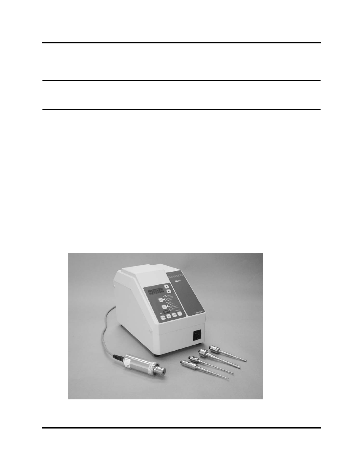
2.1 Overview of SLPt Cell Disruptor
The SLPt Cell Disruptor is often used by laboratory personnel in the medical and chemical process fields.
The system consists of the power supply, which includes allcontrols, theconverter and the tapered microtip.
Figure 2.1 SLPt Sonifier Cell Disruptor
DOC EXPIRES 12PM 9/16/2007. Article or Material must comply with the requirements
stipulated by RoHS in its current version of 1/27/03

Chapter 2: Introduction to the SLPt Cell Disruptor
Controls and Commands
2-2 100-214-252 Rev. A
The digital controls on the SLPt Cell disruptor allow for accuracy and repeatability of control settings.
Application parameters are entered into the power supply through the keypad on the front panel of the unit.
External signals are initiated via J2 (9 pin) connector on the back of the power supply. To simply generate
a start signal, a J911 Start cable, 8’, (EDP101-240-020) can be used. To control or monitor other signals
(Reset, Seek, Alarm, Ready) a J913 Start cable, 25’, (EDP101-240-072) must be used. Reset and Start func-
tions can also be performed from the front panel. Further information about these signals can be found in
Section 4.6.2. All other functions can only be performed from the front panel.
The SLPt Cell Disruptor’s power supply converts AC line voltage to 40kHz electrical energy. This high-
frequency electrical energyis fed toa converter where itis converted to mechanical vibrations. The heart of
the converter is a lead zirconate titanate electrostrictive element which, when subjected to an alternating
voltage, expands and contracts. The converter vibrates in a longitudinal direction and transmits this motion
to the tool immersed in the solution, which causes cavitation. The implosion of microscopic cavities in the
solution results, causing the molecules in the medium to become intensely agitated. The ultrasonic vibra-
tions transmitted through the tool can also be applied directly to a solid workpiece, such as tissue, through
the tool that are attached to the converter.
The SLPt Cell Disruptor is a constant amplitude device. As the load or pressure on the tool face increases,
the powersupply develops morepower to maintain the amplitude forany given outputcontrol setting.When
the tool is operated in air, it is subjected to minimum pressure, and minimum power is required to maintain
amplitude.
The load increases when the tool is immersed in a liquid; the more viscous the liquid, the higher the load
and the more power developed. If a cell that can be pressurized is used, even more power is developed. For
any given application, more power results when a tool of higher amplitude or larger radiating surface is
used, or when any tool is driven at higher amplitude by increasing the amplitude.
By setting various operation parameters, you can precisely control the way in which ultrasonics are applied
to the sample. You can:
• Specify the time duration of the experiment
• Adjust the amplitude setting between 10% and 60% of maximum amplitude (microtip 60% max-
imum)
• Prevent excessive temperature increase in the sample by setting ultrasonics to operate in Pulse
mode or in Pulse/Pause mode
• Bring a sample to a desired temperature and hold it there, varying by only a few degrees, for a
desired duration using the Pulse/Pause mode
2.2 Controls and Commands
This section describes the controls and commands that you use to operate the SLPt Celldisruptor. A detailed
description of how and when to use each front panel control, the valid formats for the data that you enter,
and the response you receive from the system when you use each of these controls is provided in Chapter
6, Operations.
The SLPt Cell disruptor is equipped with a keypad and LED display on the front panel of the unit. With the
keypad, you can set functional modes of operation and input digital parameters. Availability of the various
functions depends on the mode or state of the system. If you attempt to use a function that is not available,
you will be alerted by a beep.
DOC EXPIRES 12PM 9/16/2007. Article or Material must comply with the requirements
stipulated by RoHS in its current version of 1/27/03

SLPt Cell Disruptor Chapter 2: Introduction to the SLPt Cell Disruptor
User Manual Controls and Commands
100-214-252 Rev. A 2-3
Figure 2.2 SLPt Cell Disruptor Front-panel Controls
Some functions of the SLPt Cell disruptor can be controlled through the external input connected located
on the rear of the unit. You always have the ability to halt operation, whether control is direct or remote.
Section 2.2.2, Back Panel Connections, on page 2-5, describes the back panel of the unit.
EnterReset Test
Start/Stop
Mode
88:88
Continuous
Time(hr/min)
Time(min/sec)
Pulse
On
Off(sec)
Amplitude(%)
ExpTime(hr/min)
Set
4567
3
1
2
8
9
2B
2E
2A
3C
3E
3A
3D
2C
Autotune
DO NOT REMOVE
DOC EXPIRES 12PM 9/16/2007. Article or Material must comply with the requirements
stipulated by RoHS in its current version of 1/27/03

Chapter 2: Introduction to the SLPt Cell Disruptor
Controls and Commands
2-4 100-214-252 Rev. A
2.2.1 SLPt Cell Disruptor Keypad/Display Description
LED Display
A 4 digit LED numeric display is located on the front panel. It is controlled by the Left and Up arrow keys
located adjacently on the membrane keypad, and are used to respectively select and increment the selected
digit. This allows setup and navigation for controlling the SLPt.
Mode Select Key
Each of the 4 SLPt Modes (Continuous, Time min/sec, Time hr/min, Pulse) can be selected by pressing the
Mode key. Repeat the press to advance to the desired operational mode. The selected Mode LED will light.
Set Key
Use this key to select the parameter(s) you want to enter/update on the display (LED(s) 3A, C, D, E).
Reset Key
When an alarm occurs during the process cycle, and the Reset LED is blinking, pressing the Reset key will
clear the alarm. If the LED is not on, and RDY is displayed, pressing the Reset key will send a reset to the
power supply module.
When in the parameter entry mode, pressing the Reset will restore the original value of the parameter being
modified and then return the system to Ready. It will also reset the power supply and clear any alarms.
Test Key
The Test key is only active when the system is ready. Ultrasonics are enabled while the Test key is pressed,
and disabled when released. Test performs the run, seek, and store functions, causing the power module to
test for the resonant frequency of the converter and tool at 10% amplitude, and then go to the amplitude set-
ting.
Enter Key
Press the Enter key on the SLPt Cell Disruptor to:
• Confirm a selection setting.
• Switch between power display and experiment time remaining
• Exit the configuration menu.
If you have entered a modified parameter value, the system checks the value for validity and format. If the
value you entered is valid, the value is accepted, and it replaces the old value. The original value is lost and
cannot be recovered. If the modified value is invalid, an appropriate error message is displayed.
Start/Stop Key
The Start/Stop key is used to set up Pulse Start in the configuration menu at start up. Either: Press and hold
to run a cycle for its duration, or Press and release to start a cycle . . . press again to abort cycle.
DOC EXPIRES 12PM 9/16/2007. Article or Material must comply with the requirements
stipulated by RoHS in its current version of 1/27/03

SLPt Cell Disruptor Chapter 2: Introduction to the SLPt Cell Disruptor
User Manual Controls and Commands
100-214-252 Rev. A 2-5
Left Arrow Key
The Left Arrow key selects from right to left, causing each digit in turn to blink, and wraps back to the right.
The blinking digit is available to increment using the Up Arrow key.
In the configuration menu , the Left Arrow key toggles the function between Off (0) and On (1).
Up Arrow Key
This key will increment a selected digit, one count per press. The display will increment appropriately for
the selected parameter.
2.2.2 Back Panel Connections
Figure 2.3 Back Panel of SLPt Cell Disruptor
The back panel of the SLPt Cell Disruptor is equipped with:
• An IEC-type power cord connection for connecting the power supply to a grounded electrical
outlet.
• A fuse holder for access to a replaceable 5x20mm protective fuse. The fuse is a glass slow-blow
type (refer to the data tag for the fuse rating).
• A 3 pin RF connector to connect the power supply to the Converter.
• A User external input connector (female DB9f requires a cable with a 9-pin male DB9m
connector).
RF
SerialNum.
INPUT:
Year & Month of Manufacture
MAX POWER:
MODEL
EDP NO.
J 2
User I/O, J2
RF Out, J3
Ground Detect Terminal,
Optional Feature
Power In,
and Fuse
Unit Data Tag
DOC EXPIRES 12PM 9/16/2007. Article or Material must comply with the requirements
stipulated by RoHS in its current version of 1/27/03

Chapter 2: Introduction to the SLPt Cell Disruptor
System Features
2-6 100-214-252 Rev. A
2.3 System Features
The SLPt Cell Disruptor includes the following features:
• Front-panel system On/Off switch
• Separate front-panel Stop and Pause buttons for experiment cycles
• Power output of up to 150 Watts.
• 92 - 132 Volt and 180 - 253 Volt models available (factory set)
• Front-panel LED display, showing parameter settings, alarms and messages
• Membrane front panel with numeric keypad for parameter entry and function selection
• Digital parameter setting, with valid parameter range checking
• Pulse or Continuous operation
•DigitalTimer
• Automatic end-of-cycle audible alarm
• Factory-tuned 40 kHz ultrasonic design, requires no user adjustment
• User External Input, provides ability to remote start, seek and overload Alarm Reset. Also can monitor
Weld On, Ready and Alarm
For additional feature information, please contact your Branson representative.
DOC EXPIRES 12PM 9/16/2007. Article or Material must comply with the requirements
stipulated by RoHS in its current version of 1/27/03
Table of contents
Other Branson Laboratory Equipment manuals


