Branson Sonifier 250 User manual

Digital Sonifier®
Models 250 & 450
User’s Manual
EDP 100-214-239
Rev. A
BRANSON Ultrasonics Corporation
41 Eagle Road
Danbury, Connecticut 06813-1961 U.S. .
(203) 796-0400

EDP 100-214-239 Rev. A February 2001
Manual Change Information
At Branson, we strive to maintain our position as the lea er in ultrasonics plastics joining,
cleaning an relate technologies by continually improving the esigns, circuits an compo-
nents in our equipment. These improvements are incorporate as soon as they are evelope
an thoroughly teste .
Information concerning any improvements will be a e to the appropriate technical ocu-
mentation at its next revision an printing. Therefore, when requesting service assistance for
specific units, note the Release information foun on the cover of this ocument, an refer to
the printing ate which appears in the lower right corner of this page .
Patents and Copyright
Copyright
©
1998 by Branson Ultrasonics Corporation, Danbury, Connecticut, U.S.A.
All rights reserve .
Manual part number: EDP 100-214-239 Rev. A, printe February 2001.
Branson Ultrasonics Corporation equipment is manufacture un er one or more of the fol-
lowing U. S. Patents:
4,249,986; 4,315,181; 4,363,992; 4,551,690; 4,651,043; 4,786,356; 4,973,876; 5,095,188;
5,435,863.
Note: Sonifier
®
is a registere tra emark of Branson Ultrasonics Corporation, Danbury,
Connecticut, U.S.A. Other tra emarks an service marks respectfully mentione herein are
hel by their respective owners.

Digital Sonifier®
User’s Manual
Forward
Congratulations on your choice of a Branson Ultrasonics Corporation system!
The Branson Digital Sonifier
®
syste m is th e new e st gen e ra ti o n of pr o uct using this sop h ist i-
cate technology for a variety of customer applications. This manual shoul be kept with the
system.
Than k y ou for ch oo si n g a Bra ns on pr o uct !
Introduction to this manual
This manual is arrange into seven structure chapters which will help you fin the informa-
tion you may nee to know to safely han le, install, set up, program, operate, an /or maintain
this pro uct. A itional information is provi e in several Appen ix chapters.
In the event you require a itional assistance or information, please contact our Pro uct Sup-
port epartment (see
’How to Contact Branson’
on page 1-5 for information on how to contact
us) or your local Branson representative.

100-214-239 Rev. A
For Your Notes

100-214-239 Rev. A i-5
Digital Sonifier

100-214-239 1-1
Safety Considerations
Digital Sonifier
1 Safety and Support
1.1 Safety Considerations --------------------1-1
1.2 General Precautions ---------------------1-2
1.3 Regulatory Compliance--------------------1-3
1.4 Warranty ---------------------------1-4
1.5 How to Contact Branson -------------------1-5
1.1 Safety Considerations
CAUTION
jThe following safety considerations should be observed when operating the
Digital Sonifier®:
• Make sure that the equipment is properly grounded. DO NOT operate if it is not.
• The unit is equipped with a three-conductor cord and three-prong grounding-type plug,
and must be plugged into a three-prong grounding-type wallreceptacle. DO NOT under
any circumstances remove the power cord ground prong.
•DO NOT operate the equipment with the cover removed. High voltage is present within
the equipment when connected to plant wiring.
•DO NOT turn on the ultrasonics without the converter and horn attached.
•DO NOT touch the horn or tip when ultrasonics are active. When handling, removing, or
attaching a horn or tip, be sure that the ON/OFF switch is set to OFF. Touching the horn
or tip while the unit is on can result in serious personal injury.
•DO NOT allow the horn or microtip to contact lab stands, beakers, or similar objects.
Horn/microtip failure may result.
•DO NOT operate the equipment at more than 70% amplitude when using a microtip
horn.
• Establish a standard of operation and test equipment periodically.

1-2 100-214-239
Safety and Support
1.2 General Precautions
1.2.1 Intended Use of the System
The 250/450 Digital Sonifiers can be used to disrupt cells, bacteria, spores, or tis-
sue, and are ideal for initiating and accelerating chemical, biochemical, and phys-
ical reactions, and for de-gassing liquids. With the Digital Sonifier, you can prepare
an emulsion to 0.01 micron, homogenize immiscible liquids, polymerize some
materials, and depolymerize others.
1.2.2 Safety Measures and Guards
This manual contains operation instructions for the Digital Sonifier cell disruptor
Models 250 and 450. It contains information essential to the proper use and care
of this equipment. The manual contains notes, warnings, and cautions. These are
described as follows:
NOTE
iProvides information that the reader should follow to prevent inconvenience.
CAUTION
jAdvises the user of a hazard that can cause equipment damage or personal
injury.
WARNING
jAlerts the reader to a hazard that can result in severe personal injury.
Do NOT disregard a WARNING.
1.2.3 Safe Operation
Setup and Operation instructions are found in Chapter 6 of this manual.
For safe operation, please ensure that all people using this equipment follow those
instructions and observe all CAUTION and WARNING notices.
1. Make sure that the equipment is properly grounded. DO NOT operate if it is not.

100-214-239 1-3
General Precautions
Digital Sonifier
2. The unit is equipped with a three-conductor cord and three-prong grounding type
plug and must be plugged into a three-prong grounded receptacle. DO NOT under
any circumstances remove the power cord ground prong, or use a plug ‘Adapter’.
3. DO NOT operate equipment with the coverremoved. High voltage is present within
the equipment when connected to plant wiring.
4. Do not allow the horn or microtip to contact lab stands, beakers, etc. or horn/
microtip failure may result.
5. Establish astandard of operation and periodically test theequipment, as described
in Ultrasonic Test on page 4-17.
Although the DigitalSonifier operates outsidethe normal range of human hearing,
some applications can create audible noise above 85dB. Noise can occur, for
example, when the device touches a solid material, or when its operation causes
nearby objects in the lab to vibrate. If an uncomfortable level of noise is present,
the operator should wear ear protection for safe operation.
Appropriate eye protection should be worn when operating the Digital Sonifier, to
prevent possible splash injury originating in the solution.
WARNING
j
Never
touch the horn or tip when ultrasonics are active. Touching the horn or
tip while the unit is on can result in serious injury. When you handle, remove,
or attach a horn or tip, always make sure that the ON/OFF switch is OFF.
1.2.4 Setting Up the Workplace
The unit should be positioned away from radiators and heating vents. A fan inside
the unit maintains a safe operating temperature in the power supply by circulating
air over the components. Therefore, place the unit so that the air intake on the bot-
tom of the power supply is not blocked. Periodically, unplug the unit and clean the
air intake underneath the power supply to ensure that dust or dirt is not restricting
the flow of air. If the Digital Sonifier is to be used for remote operation, ensure that
the unit is situated within full view of the operator, to prevent injury or equipment
damage through an accidental or automatic start-up.
1.3 Regulatory Compliance
The Digital Sonifier is designed for compliance with the following regulatory guide-
lines.
• European norms EN-61010-1, EN55011, EN50082-1, ENV50140, ENV50141
• IEC 529 (IP-65 water resistant for Membrane Keypad)
The Digital Sonifier is CE compliant.

1-4 100-214-239
Safety and Support
1.3 Warranty
Refer to the “Terms and Conditions of Sale” found on the back of your Invoice for
information about the product Warranty issued of your Branson products. If you
have any questions, please contact your Branson representative. The product war-
ranty information is summarized below.
WARRANTY
When used in accordance with written instructions and under normal operating
conditions, Branson Ultrasonics Corp. equipment is guaranteed to be free of
defects in MATERIAL and WORKMANSHIP for two (2) years from the date of orig-
inal delivery by BRANSON or by an authorized representative. Any unit which
proves defective during the stated period will be repaired free of charge or replaced
at the sole discretion of Branson Ultrasonic S.A., 9, ch. Faubourg-de-Cruseilles,
CH-1227 Carouge/Geneva or an authorized repair station as advised by BRAN-
SON, providedthe defectiveunit is returnedproperly packedwith all transportation
charges prepaid. A limited warranty as specified may apply to certain components
of the equipment.
WARRANTY EXCEPTIONS
This warranty shall not apply to equipment subjected to misuse, improper installa-
tion, alteration, neglect, accident or improper repair.
This warranty is limited to the original purchaser and is not transferable.
Horns and tips fabricated by Branson for use in equipment described in this manual
are manufactured to exacting parameters. Using altered or modified horns and tips
or horns and tips otherwise unqualified by Branson can produce undue stresses
that may damage the equipment. Equipment failures resulting from using unquali-
fied horns and tips are not covered by the Branson warranty.
Microtips are designed to give maximum mechanical energy output. Since they
operate close to the stress limits of titanium, Branson cannot guarantee microtips
against failure.
CONTACT YOUR BRANSON REPRESENTATIVE OR BRANSON ULTRASON-
ICS CORPORATION, DANBURY, CONNECTICUT, SHOULD YOU HAVE ANY
QUESTIONS CONCERNING HORN QUALIFICATION.

100-214-239 1-5
How to Contact Branson
Digital Sonifier
1.4 How to Contact Branson
The mailing address and telephone information for Branson is as follows:
Branson Ultrasonic SA
9, chemin Faubourg-de-Cruseilles / P.O. Box 1031
CH-1227 Carouge/Geneva
Phone : +41-22-304 83 58 Fax: +41-22-304 83 59
Tell the operator which product you have and which person or department you
need. If after hours, please leave a voice message with your name and return tele-
phone number.
1.4.1 Before Calling Branson for Assistance
This manual provides information for troubleshooting and resolving problems that
could occur with the equipment (see Chapter 7). If you still require assistance,
Branson Product Support is here to help you. The following questionnaire lists the
common questions you will be asked when you contact the Product Support
department, to help identify the problem.
Before calling, determine the following information:
1. Your company name and location.
2. Your return telephone number.
3. Have your manual with you. If troubleshooting a problem, refer to Chapter 7.
4. Know your equipment model and serial numbers (found on a gray data label on the
units). Information about the Horn (part number, gain, etc.) or other tooling may be etched
into the tooling. Software- or-firmware based systems may provide a BOS or software ver-
sionnumber,whichmayberequired.(TheDigitalSonifierprovidesthefirmwareinformation
on the start-up screen.)
5. What tooling (horn) and booster are being used?
6. What are the setup parameters and mode?
7. Is your equipment in an automated system? If so, what is supplying the “start” signal?
8. Describe the problem; provide as much detail as possible. For example, is the problem
intermittent? How often does it occur? How long before it occurs if you are just powering
up? If an error is occurring, which error (give error number or name)?
9. List the steps you have already taken.
10. What is your application, including the materials being processed?
11. Have a list of service or spare parts you have on hand (tips, horns, etc.)

1-6 100-214-239
Safety and Support
Returning Equipment for Repair
Before sending equipment for repair, provide as much information with the equip-
ment to help determine the problem with the system. Fill in any details below or on
a separate sheet.
1. Describe the problem; provide as much detail as possible. For example, is this a
new problem? Is the problem intermittent? How often does it occur? How long
before it occurs if you are just powering up?
________________________________________________________________
________________________________________________________________
________________________________________________________________
2. Is your equipment in an automated system? If so, is the problem related to Start/
Stop control, or interaction with PLC’s or other devices, etc.?
3. If the problem is with an external signal or output, which one?
If known, include plug/pin # (e.g., P29, pin #3):
__________________________________
4. What are the setup parameters?
________________________________________________________________
________________________________________________________________
5. What is your application (e.g., continuous, pulse, temperature, etc.)?
________________________________________________________________
6. Name and phone number of the person most familiar with the problem:
________________________________________________________________
7. Notify the Branson office prior to shipping the equipment.
NOTE
iTo Return Equipment to Branson, you must first obtain an RGA number from
a Branson representative, or the shipment may be delayed or refused.
8. For equipment not covered by warranty, include a purchase order for the repair
costs to avoid delay.
9. Pack carefully in original packing material to avoid damage in shipment.
10. Return general repairs by any desired method. Send priority repairs by air freight.
11. Prepay the transportation charges FOB Danbury, Connecticut, U.S.A.
Notes:
________________________________________________________________
________________________________________________________________
________________________________________________________________

100-214-239 1-7
How to Contact Branson
Digital Sonifier
Returning Equipment for Repair (to Geneva facility)
NOTE
iTo return equipment to Branson, you must first obtain an RGA number from
a Branson representative, or the shipment may be delayed or refused.
If you are returning equipmentto Branson for repair, you must first call the Danbury
Repair department to obtain a Returned Goods Authorization (RGA)number.(If
you request it, the repair department will fax a Returned Goods Authorization form
to fill out and return with your equipment.)
Branson Ultrasonic SA
9, chemin Faubourg-de-Cruseilles / P.O. Box 1031
CH-1227 Carouge/Geneva
Phone : +41-22-304 83 58 Fax: +41-22-304 83 59
• Provide as much information as possible that will help identify the need for repair.
• Carefully pack the equipment in original packing cartons.
• Clearly label allshipping cartons with the RGA number on the outside of cartons as well
as on your packing slip, along with the reason for return.
• Return general repairs by any convenient method. Send priority repairs by air freight.
• You must prepay the transportation charges FOB Danbury, Connecticut, U.S.A.
Obtaining Replacement Parts
You can reach Branson Parts Store at the following telephone numbers:
Branson Part Store
direct telephone number: +41-22-304 83 58
fax number: +41-22-304 83 59
Many parts can be shipped the same day if ordered before 2:30 p.m., Eastern time.
A parts list is found in Section 7 of this manual, listing descriptions and EDP part
numbers. If you need replacement parts, coordinate the following with your pur-
chasing agent:
• Purchase order number
• ‘Ship to’ information
• ‘Bill to’ information
• Shipping instructions (air freight, truck, etc.)
• Any special instructions (for example, “Hold at the airport and call”). Be sure to give a
name and phone number
• Contact name information

1-8 100-214-239
Safety and Support
For Your Notes

100-214-239 Rev. A 2-1
Overview of Digital Sonifier
Digital Sonifier
2 Introduction to the Digital Sonifier
2.1 Overview of Digital Sonifier------------------2-1
2.2 Controls and Commands -------------------2-3
2.3 System Features -----------------------2-9
2.1 Overview of Digital Sonifier
The 250/450 Digital Sonifier is often used by laboratory personnel in the medical and chemical
process fields. The system consists of three core elements: the power supply the controls and
the converter and horn. The system can interface with customer equipment including a remote
computer or terminal dot matrix printer temperature probe and User I/O.
Figure 2.1 Digital Sonifier
Power Switch
Amplitude Control
Front
Panel
Keypad
Bargraph
LCD Display
Select keys
and
Arrow keys

2-2 100-214-239 Rev. A
Introduction to the Digital Sonifier
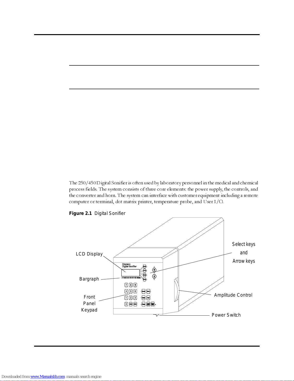
The 250 and 450 Digital Sonifiers differ only in their output power ratings measured when the
output control is at maximum setting. The 250’s maximum available output power is up to 200
watts; the 450’s maximum available output power is up to 400 watts.
The digital controls on the Digital Sonifier allow for accuracy and repeatability of control set-
tings. You enter application parameters into the system either through the keypad on the front
panel of the unit or remotely through a computer keyboard and can save up to twenty (20)
sets of preset control parameters. Y ou can view operating parameters through the twenty-char-
acter four-line LCD display on the unit control panel and on a remote terminal if one is con-
nected. At System Setup you can select a language for the display: English German French
Italian or Spanish.
The Digital Sonifier’s power supply converts AC line voltage to 20kHz electrical energy. This
high-frequency electrical energy is fed to a converter where it is converted to mechanical vibra-
tions. The heart of the converter is a lead zirconate titanate electrostrictive element which
when subjected to an alternating voltage expands and contracts. The converter vibrates in a
longitudinal direction and transmits this motion to the horn tip immersed in the solution
which causes cavitation. The implosion of microscopic cavities in the solution results causing
the molecules in the medium to become intensely agitated. The ultrasonic vibrations transmit-
ted through the horn can also be applied directly to a solid workpiece such as tissue through
a variety of different tips that can be attached to the horn.
The Digital Sonifier is a constant amplitude device. As the load or pressure on the horn face
increases the power supply develops more power to maintain the amplitude for any given out-
put control setting. When the horn is operated in air it is subjected to minimum pressure and
minimum power is required to maintain amplitude.
The load increases when the horn is immersed in a liquid; the more viscous the liquid the
higher the load and the more power developed. If a flow-through cell that can be pressurized
is used thereby increasing pressure on the horn even more power is developed. For any given
application more power results when a horn of higher amplitude or larger radiating surface is
used or when any horn is driven at higher amplitude by increasing the amplitude.
By setting various operation parameters you can precisely control the way in which ultrasonics
are applied to the sample. You can:
• Specify the time duration of the experiment
• Adjust the amplitude setting between 10% and 100% of maximum amplitude
(microtip 70% maximum)
• Prevent excessive temperature increase in thesample by setting ultrasonics to
operate in Pulse mode or in Pulse/Pause mode
• Bring a sample to a desired temperature and hold it there, varying by only a few
degrees, for a desired duration using the Pulse/Pause mode
• Set the maximum allowable temperature in the sample, so that ultrasonics will
stop automatically when the specified temperature is reached

100-214-239 Rev. A 2-3
Controls and Commands
Digital Sonifier
2.2 Controls and Commands
This section describes the controls and commands that you use to operate the Digital Sonifier.
A detailed description of how and when to use each front panel control the valid formats for
the data that you enter and the response you receive from the system when you use each of
these controls is provided in
Chapter 6, Operations
.
The Digital Sonifier is equipped with a keypad and LCD display on the front panel of the unit.
With the keypad you can set functional modes of operation and input digital parameters. Avail-
ability of the various functions depends on the mode or state of the system. If you attempt to
use a function that is not available you will be alerted by a beep.
Figure 2.2 Digital Sonifier front-panel Controls
MODEL 450 SONIFIER
COPYRIGHT 1997
Digital Sonifier®

2-4 100-214-239 Rev. A
Introduction to the Digital Sonifier
Operation of the Digital Sonifier can also be controlled through a remote computer terminal or User I/O
device. You always have the ability to halt operation whether control is direct or remote.
Each key on the front panel of the unit except for the numeric keys Print and Test has an LED indicator near
it. When the key is active the LED is turned on. Some of the keys on the Digital Sonifier keypad have equivalent
commands (preceded by !) that can be entered through the remote terminal’s keyboard.
•Section 2.2.1, Digital Sonifier Keypad Description, beginning on page 2-4, describes each key on the
Digital Sonifier keypad and identifies its equivalent remote terminal command (preceded by an ! excla-
mation point) if applicable.
•Section 2.2.2, Remote Terminal Commands, beginning on page 2-7, provides a detailed description of
all remote terminal commands. Section 2.2.3, Back Panel Connections, on page 2-8, describes the back
panel of the unit.
2.2.1 Digital Sonifier Keypad Description
LCD Display
The front panel is equipped with a four-line 20-character display screen where menus parameter options mes-
sages and warnings are displayed. If the data being displayed has more than one page you can navigate up and
down in the display by pressing the Page Up and Page Down arrow keys.
The first page of a typical Ready display.
If you wish to see the second page, press
the Down Arrow button.
The second page of a Ready display.
If you wish to see the first page, press the
Up Arrow button.
PRESET ID#16
TIME= 0:12:52 hr/m/s
MAX. TEMP= 104.3°F
AMPLITUDE= 43 %
PULSE ON= 2.1 SEC
PULSE OFF= 1.6 SEC
PULSE TEMP= ___._ F
PROBE TEMP= 67.6°C

100-214-239 Rev. A 2-5
Controls and Commands
Digital Sonifier
Line Select Keys
There are four Line Select keys to the right of the display. When a Line Select key is active the
LED next to it is turned on. You can press a Line Select key to:
• Select a line in the Parameter Entry menu display for a parameter entry.
• Toggle values in a parameter or System Setup submenus (for example, Yes or
No).
• Select an item from the options available when the system issues a warning/
error message.
Once a Line Select key is pressed its LED is turned off. When you begin entering a value for
a parameter you selected with a Line Select key all the other Line Select keys become inactive
and their LEDs are also turned off until you complete the parameter entry. If you have selected
a line but have not begun to enter a value the other Line Select keys remain active and you can
select another line on which to enter a parameter value.
Page Up and Page Down Keys
The Page Up and Page Down arrow keys are active when you are displaying a menu that has
more than one page. You can use the Page Up and Page Down keys to move up and down in
the menu. If there are more menu items above the page you are viewing the Page Up arrow is
active and its LED is turned on. If there are menu items below the page you are viewing the
Page Down arrow is active and its LED is turned on.
Start/Stop Key (!ON and !OFF Commands)
The Start/Stop key and !ON command are active during Parameter Entry mode (except when
you are changing a parameter value) and during the Sonics Active displays. When you press the
Start/Stop key or type in the !ON Command the experiment is executed and the LED next
to the key is turned on. When you press the Start/Stop key again or type in the !OFF com-
mand the experiment is stopped and the LED is turned off.
Setup Key
The Setup key is active during Parameter Entry mode (except while you are changing a param-
eter value) and while you are viewing the Setup Menu. When you press the Setup key the first
page of the Setup menu is displayed and the Setup key’s LED is turned on. When you press
the Setup key again the Setup menu is closed and its LED is turned off.
Test Key (!TS Command)
The Test key and the !TS command are active when the system is in the Ready state. When you
press the Test key or type in the !TS command ultrasonics are enabled for two seconds. To
turn on ultrasonics for another two seconds you can press the Test key or type in the !TS com-
mand again.

2-6 100-214-239 Rev. A
Introduction to the Digital Sonifier
Pause Key (!H Command)
The Pause key and the !H command are active only when the unit is operating. When you press
the Pause key or type in the !H command operation of the unit halts and the Pause key’s LED
is turned on. When you press the Pause key or type in the !H command again the unit resumes
operation and the LED is turned off.
Recall Key (!R Command)
The Recall key and the !R command are active only during Parameter Entry mode except when
you are changing a parameter value. When you press the Recall key or type in the !R command
a message is displayed and the LED is turned on. Refer to
Section 6.6, Save and Recall Presets,
on
page 6-40 for information on how to save and recall presets.
Save Key (!SV Command)
The Save key and the !SV command are active during Parameter Entry mode except when you
are changing a parameter value. When you press the Save key or type in the !SV command a
message is displayed and the LED is turned on. Refer to Section
Section 6.6, Save and Recall Pre-
sets,
on page 6-40 for information on how to save and recall presets.
Print/Send Key (!P and !S Commands)
The Print/Send key and the !P and !S commands are only active after a test or experiment has
been executed and before another test or experiment begins or the Setup menu parameters are
changed. For this function to operate a printer a remote terminal or both must be enabled.
When you press the Print/Send key report data is sent to the remote terminal and to the
printer . Refer to
Section 6.7, Printing/Sending Reports,
on page 6-41 for a description of the data
that is sent to the terminal and printer.
Enter Key
You can press the Enter key on the Digital Sonifier or on the computer keyboard to:
• Cause the system to accept a modified parameter value
• Clear an error/warning message.
• Store a Setup parameter value
If you have entered a modified parameter value the system checks the value for validity and
format. If the value you entered is valid the value is accepted and it replaces the old value. The
original value is lost and cannot be recovered unless it has been stored under a preset ID num-
ber. If the modified value is invalid an appropriate error message is displayed.

100-214-239 Rev. A 2-7
Controls and Commands
Digital Sonifier
Clear Key
The Clear key on the Digital Sonifier is active at any time when a parameter can be changed.
If you press the Clear key when you are modifying a parameter value the entry field becomes
blank and the cursor is moved to the least significant position. If you press the Enter key while
the entry field is blank no value is stored for the parameter.
Numeric Keys
The keys for 1 through 9 and 0 are active at any time when a parameter has been selected to
be changed.
2.2.2 Remote Terminal Commands
This table describes the remote terminal commands and their functions. All of the remote ter-
minal commands must be preceded by an exclamation point. Refer to
Chapter 6
Operations
for
a description of the system’s response to each of these commands and the actions you should
take at each response.
Table 2-1: Remote Terminal Commands
Send this
command... When you want to...
!T Enter the TIME duration value.
!MT Enter the MAXIMUM TEMPERATURE value.
!PO Enter the PULSE ON time value.
!POF Enter the PULSE OFF time value.
!PPT Enter the Pulse Temperature value.
!S Send all report data to the remote terminal.
!P Print all report data, if a printer is enabled.
!R Recall a particular preset.
!H Pause operation of the Digital Sonifier until you send another !H
command.
!MT Enter the Maximum Temperature value.
!TS Test the system for two seconds.
!ON Start the experiment.
!OFF Stop the experiment.
!KL Lock out the keypad on the front panel. The keypad is enabled
again if you send another !KL command, or if you turn the power off
on the Digital Sonifier and then turn it on.
!SV Save the parameters entered.
!RP View all the test or experiment parameter values.
Other manuals for Sonifier 250
1
This manual suits for next models
1
Table of contents
Other Branson Laboratory Equipment manuals