PowerBox Systems Competition SR2 User manual

INSTRUCTION MANUAL
04/2021
PowErBox
CompEtition Sr2

2PowerBox-Systems − World Leaders in RC Power Supply Systems
Dear PowerBox customer,
It is now ten years ago to the month that the rst Competition SRS was introduced.
At that time it represented a milestone in the redundant deployment of receivers
using our new type of bus technology. The unrestricted output assignment, ser-
vo matching and linking to early telemetry systems were unique features, and re-
mained so for a long time.
Technology has continued to develop, and modellers’ requirements have become
more exacting. Here at PowerBox Systems we are proud to present our latest de-
velopment: the PowerBox Competition SR2. Incorporating a new external look and
the very latest technology, this single unit integrates more than twenty years of ex-
perience in the design and construction of airborne electronics.
The external changes are immediately evident: the most obvious and eye-catching
feature is the new full-colour TFT screen, which is clearly legible even in full sunshi-
ne. The size of the screen has allowed us to include a self-explanatory menu struc-
ture which is so simple to use that its operation has raised not a single query from
our test-pilots. Another obvious change is the large heat-sink, machined from solid
metal, which signicantly enhances the performance of the power supply. At the
same time we were able to reduce the overall size of the Competition SR2 subs-
tantially. The associated Sensor-Switch and TFT screen are also housed in a ma-
chined aluminium case, matching the quality appearance of the SR2 itself.
However, the most signicant innovations only become evident once the unit is
switched on. The main display contains all the essential data - including battery
voltage, current, consumed capacity and all receiver-relevant information - which
can be viewed at a glance. The screen also displays status messages concerning
the iGyroSAT or GPS III, if connected to the system.
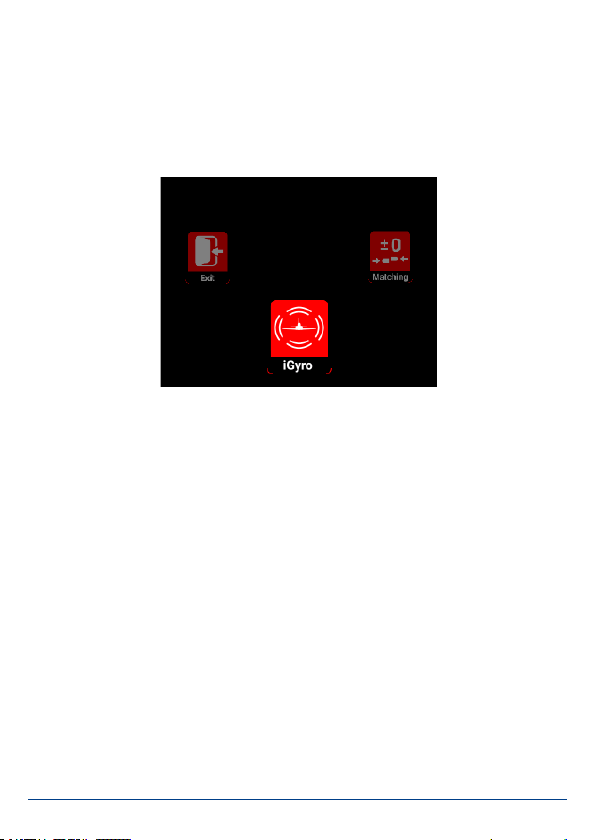
The menu system is clearly and logically laid out, and includes many new functions
as well as the familiar menu points - and all in two languages: German and English!
Important new features implemented in the new Competition SR2 include the most
efcient and sophisticated iGyro technology ever developed by PowerBox Systems.
Used in conjunction with the optional iGyroSAT sensor, the system offers twelve
gyro axes which cater for every existing model variant. The highly rened Setup
Assistant enables the pilot to set up complex models, such as types with dual thrust
vectors, ailerons and tailerons, in just a few minutes. Once the Assistant has been
completed, the transmitter channels are assigned, the directions of gyro effect are
set, and the servos connected to the outputs.

www.powerbox-systems.com 3
Each gyro axis can also be nely adjusted individually from the transmitter using
separate channels. If an initial test-ight shows up a need to ne-tune the iGyro to
meet individual requirements, a whole series of Expert settings cover every possible
need.
The servo matching feature is now displayed in graphic form on the screen, and the
PowerBox Competition SR2 also allows the servo response to be adjusted using
ve curve points. A new development is automatic servo matching. It is a very sim-
ple matter to assign and select one or two servos in addition to the primary one,
and these two or three servos can be matched accurately to each other in just a few
seconds with a single button-press!
The Competition SR2 incorporates two independent door sequencers. The stan-
dard function is designed for a retractable undercarriage, while the second can
be used to implement systems such as a latching canopy control system without
any additional devices. The Setup Assistant is capable of setting up the rst door
sequencer in just a few minutes, and three modes of operation are available. The
graphic on-screen display makes additional non-standard settings very easy to set
up; the entire sequential process can be observed at a glance.
If you use a PowerBox or Jeti RC system, virtually all* the functions of the Compe-
tition SR2 can be controlled and adjusted from the transmitter. The SR2 caters for
every aspect of telemetry for battery and receiver data with all supported systems.
If a GPS III is connected, then GPS data are also available - limited only by the faci-
lities of the RC system in use.
*except the sequencers and Setup Assistant

4PowerBox-Systems − World Leaders in RC Power Supply Systems
FEATURES
+ 22 channels
+ High-performance battery backer with high continuous load capacity
+ 2.4” TFT-screen, legible in sunlight
+ Bi-lingual menu system
+ Consistent duplication of all power electronics
+ Redundant electronic switch
+ Servo matching for all 22 outputs
+ Auto matching function
+ Two independent door sequencers with Setup Assistant
+ The latest integrated iGyro technology, using the iGyroSAT as gyro sensor
+ Twelve independent gyro outputs for: 4x aileron, 4x elevator, 4x rudder
+ Individual gain control for all twelve gyro outputs
+ Special regulatory algorithm for xed-wing models
+ System detects all transmitter mixers
+ Four selectable output voltages: 6.0 V, 7.4 V, 7.8 V or unregulated
+ Graphic menu diagrams ensure ultra-simple programming
+ Fast basic setup procedure using the sophisticated Assistant
+ Optional GPS III for speed-dependent gyro compensation
+ Telemetry data for PowerBox P²BUS, Futaba S.BUS2, Jeti Ex-BUS, Spektrum
SRXL2, Multiplex M-Link and Graupner HoTT
+ Transmission of battery, receiver and GPS* data
+ Virtually all features can be controlled from PowerBox and Jeti transmitters
+ Selectable servo frame rate: 10ms, 12ms, 14ms, 16ms, 18ms
+ Servo feedback current suppression
+ Latest 32-bit micro-processor for precise, high-speed signal processing
+ High-performance machined heat-sink for optimised heat diffusion
+ Machined, anodised aluminium switch and screen case
+ Compact dimensions
*with GPS III connected

www.powerbox-systems.com 5
1.INITIAL INSTALLATION: GENERAL SEQUENCE OF OPERATIONS
When installing the unit it is important to keep to the standard sequence described
below, and adhere to the subsequent setup stages, as this ensures that your instal-
lation of the Competition SR2 will be swift and problem-free. The individual points
are explained in full in the remainder of these instructions:
- Mounting the PowerBox, switch and screen
- Connecting the receiver and batteries
- Settings in the General Settings menu
- Setting up all the functions at the transmitter
- Carrying out the Setup Assistant
- Carrying out the Door Sequencer Assistant1
- Assigning all remaining functions in Output Mapping
- Setting up all control surface travels, ight modes, Dual-Rate, Expo etc. at the
transmitter
- Using Servo Matching to equalise servos operating in parallel
- Learning the stick end-points in the iGyro menu 2
- iGyro set-up ight 2
- Fine-tuning the iGyro 2
1 not required if wheel doors are not present
2not required without a gyro
2. INSTALLATION, CONNECTIONS
a) Mounting
The Competition SR2 should be mounted in the model on a robust sub-struc-
ture using the four screws, rubber grommets and brass eyelets supplied in the
set. The installed location is not important, but if an iGyroSAT is to be used, the
sensor must be installed perpendicular to the model’s centreline. Ideally the TFT
screen should be in a clearly visible location. The very bright screen lighting ma-
kes it easy to read even in full sunshine, so no special provisions have to be made
here. The screen is connected to the socket marked Display on the side of the
PowerBox.

6PowerBox-Systems − World Leaders in RC Power Supply Systems
The switch should be mounted in the fuselage side. As with previous units, a
wooden doubler should be glued to the inside of the switch aperture - especially
if the fuselage is made of GRP - in order to avoid subjecting the switch to pow-
erful vibration. The set includes a template for the switch aperture. An exposed
switch is often undesirable in scale models, and for such applications we offer
an alternative switch in the shape of the MagSensor. However, please note that
the SensorSwitch is required for the programming procedure - unless you are
using a Core or Jeti RC system - and for this reason it should always be available
for use. The SensorSwitch is plugged into the socket marked Switch on the side
of the PowerBox.
b) Receivers
Once you have installed the Competition SR2, the screen and the switch, it is
time to connect the receivers. In principle all SRS PowerBox systems are totally
reliable when used with a single receiver. However, in view of the low cost of a
second receiver compared with the value of the model, we always recommend
installing a second receiver.
Ideally the receivers should be spaced well apart inside the model, as this increa-
ses the likelihood that at least one receiver will have good reception at all times
- even under difcult reception conditions. It is permissible to extend the serial
bus connection between receiver and backer to any length, as the signal is digital,
and therefore extremely resistant to external inuences.
The PowerBox Competition SR2 can be used with a wide range of radio control
systems: PowerBox CORE P²BUS, Futaba S.BUS2, Jeti EX-BUS, Spektrum SRXL2,
Multiplex M-Link and Graupner Hott. The rst four systems share one common
feature: servo signals and telemetry data are carried on a bus system, and this al-
lows the receivers to be connected to the Competition SR2 using a single patch
lead each. Multiplex and Hott systems require an additional connection between
the telemetry output of the PowerBox and the receiver’s telemetry input.
The Competition SR2 automatically detects the system to which it is connected.
However, when the radio is rst switched on it may take a few seconds before the
system is unambiguously recognised. Once detected, the unit stores the system
type, and it will start immediately next time it is switched on.
• PowerBox CORE
Connect one or two receivers to RX1 and RX2 at the P²BUS output. If only one
receiver is to be used, it must be connected to RX1 to provide telemetry trans-

www.powerbox-systems.com 7
mission. If a GPS III is connected to the FastTrack input, the Competition also
delivers GPS data to the transmitter.
• Jeti EX-BUS
One output of the receivers you intend to use must be set to EX-BUS. The frame
rate should be set to 10ms, and the Failsafe function must be OFF. If you intend
to use only one receiver, then it must be connected to RX1 to transmit telemetry
data. If a GPS III is connected to the FastTrack input, the Competition also deli-
vers GPS data to the transmitter. Only the REX-Type receivers are supported
• Futaba S.BUS2
Connect one or two receivers to RX1 and RX2 at the S.BUS2 output. If only one
receiver is to be used, it must be connected to RX1 to provide telemetry transmis-
sion. This receiver must also be dened as the telemetry receiver at the transmit-
ter. In order to receive telemetry data you must carry out a Load New process in
the Telemetry Sensor menu; this action completely erases the sensor list. Now
select Slot 16 in the sensor list, and select PowerBox. The telemetry data now
appear in Slot 16 or later. If a GPS III is connected to the FastTrack input, the
Competition also delivers GPS data to the transmitter.
• Spektrum SRXL 2
Connect one or two SPM4651T satellites to the Competition SR2 using the optio-
nal adapter lead set (#9192). If only one receiver is to be used, it must be connec-
ted to RX1 to provide telemetry transmission. At the transmitter you will now see
the battery data displayed under PowerBox Sensor. If a GPS III is connected to
the FastTrack input, the Competition also delivers GPS data to the transmitter.
By default the Competition works in DX18 compatibility mode.
• Multiplex M-Link
Set the B/D sockets of the receivers you intend to use to SRXL V2. This gives you
sixteen channels. The Failsafe function must be OFF.
To use telemetry you must disable the Telemetry function of one receiver using
Multiplex Launcher. The Tele output of the PowerBox should be connected to the
Sensor input of the other receiver.
Note: do not attempt to register the PowerBox as a sensor at the transmitter;
this function is not implemented.

8PowerBox-Systems − World Leaders in RC Power Supply Systems
If a GPS III is connected to the FastTrack input, the Competition also delivers GPS
data to the transmitter.
• Graupner Hott
Set one output of both receivers to SUMD-OF16. For example, if the receiver is a
GR16/24, this will be output 8. Connect these outputs to the RX1 and RX2 inputs
of the PowerBox. If a GPS III is connected to the FastTrack input, the Competition
also delivers GPS data to the transmitter.
For the telemetry function you must connect the TELE output of the PowerBox to
the Telemetry input of one receiver.
c) Connecting the batteries
It is possible to use 2S LiPo, 2S LiIon, 2S LiFePo or 5S NiMH batteries with the
Competition SR2. We recommend that you use our PowerPaks, which feature
integral charge electronics. The fundamental rule regarding battery size is that
one battery on its own should be capable of powering the model reliably.
If you intend to assemble your own batteries please note that correct polarity is
vitally important. The unit does not include reverse polarity protection, as this
would involve performance losses.
3. SWITCHING ON AND OFF
This is the procedure for switching the PowerBox on: hold the SET button pressed
in until the LED glows red. Continue to hold it pressed in while you also press but-
tons I and II briey to conrm the switching process. This method enables you to
switch the batteries on individually; for example, in order to check that both packs
are working properly, and deliver sufcient current when all the control surfaces
are moved.
The same procedure is used to switch off.
Note: connecting a battery to the PowerBox with incorrect polarity, even very
briey, will immediately destroy the voltage regulators!
Note: only one receiver (Bind A or Bind B) can transmit telemetry!

www.powerbox-systems.com 9
The TFT screen now displays the following image:
Analogue battery voltage display, with recorded minimum value. The momen-
tary value is indicated by the red line, while the grey line indicates the minimum
voltage which occurred during the ight. The scale of the analogue display is
automatically adjusted to suit the battery type you have selected. The supple-
mentary digital display indicates the exact value.
The two analogue markers show the current being drawn from the right and
left battery. The digital current gure shows the sum of the currents at both
inputs.
Shows the voltage present at the output.
The consumed capacity is displayed separately for both batteries. It can also
be reset from the transmitter if you assign a channel to this function.
All status messages are displayed at this point: receiver status and lost fra-
mes; gyro and GPS status if connected.

10 PowerBox-Systems − World Leaders in RC Power Supply Systems
4. MAIN MENU
To access the menu you need to hold the SET button pressed in for about 2 - 3
seconds, after which you can select the desired menu using buttons I and II. Within
the individual menus the selected menu point is always displayed in red.
Press the SET button once you have selected a menu point. You can now alter the
values and settings using buttons I and II.
The “Rotary Menu” shown above contains the following sub-menus:
• iGyro
Here you will nd all the settings relating to the iGyro. These features are only
available if an iGyroSAT is connected to the unit.
• Matching
If you have servos which are mechanically inter-connected, you can use this sub-
menu to adjust them to match each other using a ve-point curve. You will also
nd the Auto Matching function here.
• Sequenzer
At this point you can set up the two independent door sequencers, either manual-
ly or with the help of the Assistant.
• Output
In this menu you can assign all 22 outputs directly to any transmitter channel, to
a Gyro output or to one of the two sequencers.

www.powerbox-systems.com 11
• Input
The transmitter channels are assigned to the iGyro or sequencer here.
• General
This menu is used to alter fundamental settings such as the language or frame
rate.
• Assistent
Always use the Setup Assistant when you are preparing a new model for its rst
ight. This is where the transmitter input channels are determined, the model
type selected, and the servos assigned to the outputs. In just a few minutes the
primary functions can be ready for use, and the Assistant procedure makes it
much easier to set up the gyro functions at a later stage.
5. GENERAL SETTINGS
Before you start using the primary functions (with the help of the Setup
Assistant) and connect the servos, you should enter the basic settings
in the General Settings menu.
• Radio control system
This menu point cannot be selected manually. As already mentioned, the unit au-
tomatically detects the radio control system. If you have already connected your
receivers and bound them to the transmitter, you will see at this point the radio
control system it has detected.

12 PowerBox-Systems − World Leaders in RC Power Supply Systems
• Regulator output
Here you can select your preferred output voltage: you can choose between 6.0V,
7.4V, 7.8V and unregulated output.
We recommend the 7.8V option even for HV servos, as this setting ensures that
your servos operate with constant torque and transit speed for a long period after
switching on. The higher voltage of the batteries, which is only present for a brief
period after charging, is reduced to a level which the battery can maintain for
longer.
• Frame rate
The default setting for this is 16ms, at which all current servo types operate reliab-
ly. Digital servos can deliver better performance if you set the frame rate to 12ms.
Older analogue servos, on the other hand, may become hot if the frame rate is set
too low, and will not be able to nd their commanded position accurately.
• Capacity reset channel
Enter a channel at this point which you wish to use to reset the consumed battery
capacity. The capacity is reset when the selected channel is moved to +100%.
• Language
Select German or English as menu language.
• Reset options
This menu point takes you to a sub-menu in which you can reset various settings
individually or jointly.
6. SETUP ASSISTENT
The Setup Assistant is designed to help you complete basic channel
and servo assignments quickly and easily. We recommend that you
continue to use the Setup Assistant even if you are very familiar with
the workings of PowerBox products. You should also use the Assistant
even if you (temporarily) do not wish to use an iGyroSAT.
On the one hand the Assistant simplies operations, because the menu initially re-
fers to outputs in general terms, such as DIRECT-xy, but once you have completed
the Assistant it uses specic designations, for example, Right aileron … etc.
On the other hand it is possible to retro-t an iGyroSAT without having to re-program
the battery backer.

www.powerbox-systems.com 13
All assignments are already complete, and even the servo matching is maintained.
Before you select the Setup Assistant, establish all the primary functions at the
transmitter, ideally with 50% travel. Mixers such as delta, tailerons and thrust vector
must also be programmed at the transmitter before you start. Check the functions
using your transmitter’s servo monitor. At this stage servo centre positions and di-
rections of rotation do not matter.
If you also intend to use an iGyroSAT, you should now install the gyro sensor in
a suitable position, perpendicular to the fuselage centreline, and connect it to the
socket marked FastTrack on the Competition SR2. If you are also using a GPS III as
telemetry sensor (and for gyro speed compensation), this should also be connected
to the FastTrack input using a Y-lead.
Select the Assistant widget in the Main Menu, and you will see the following dis-
plays:
In the rst display you select the wing type (Normal / Delta) and the tail type
(Normal, Tailerons or V-tail). You can also determine whether the model has a thrust
vector system (Single or Dual).
On the next screen you enter the number of servos you wish to assign to individual
control surfaces. The Assistant supports a maximum of three servos per control
surface. This means: if your model is tted with six aileron servos, enter 3 for the
right aileron and 3 for the left aileron.
Note: When setting up the PowerBox Competition SR2 for the rst time, please
keep to this sequence:
Setup Assistant (basic setup) –> Sequencer Assistant –> manual output
assignment of all other functions.

14 PowerBox-Systems − World Leaders in RC Power Supply Systems
You will now see further screen displays which vary according to the data you have
already entered. The following illustrations show the aileron channel as an example,
based on the above data:
The left-hand picture shows the empty display. Now move the aileron stick at the
transmitter: the PowerBox checks the input: in this example four channels should
move.
The right-hand picture shows which channels have been detected, and the outputs
to which you should connect the servos. Bearing in mind that your individual trans-
mitter’s channel sequence may not be as shown above, you may need to move the
transmitter stick briey and repeatedly until the detected channels appear after the
appropriate functions.
Repeat the procedure with the elevator and rudder functions. After this you will be
asked to enter the Gain channel for the iGyro.
Note: If multiple servos are mechanically coupled to a single control surface,
disconnect the linkage to servos 2 and / or 3, as the servos are not yet matched
to each other, and you could stall them!

www.powerbox-systems.com 15
You need to assign a channel with +/-100% travel to a rotary control at the transmit-
ter. Even if you have not connected an iGyroSAT, this action is recommended as it
will make it easier to retro-t the gyro.
If you have selected a thrust vector function, you will see a second query regarding
the sensitivity of the thrust vector control system. This is the method the Assistant
uses to set up the basis for a simple but effective method of adjusting gyro gain in
ight.
Once you have assigned the Gain control, press Continue to conrm your choice.
If no iGyroSAT is connected, this concludes the Setup Assistant.
If an iGyroSAT is connected, the next step is to establish the installed orientation
of the iGyroSAT:

16 PowerBox-Systems − World Leaders in RC Power Supply Systems
This is accomplished by moving the model in the directions shown in the graphic
display: rst move the tail of the model up and down two or three times. You will
see that the elevators follow this movement every time - the direction of effect is
not important at this stage.
At the end of the movement hold the model’s tail up and wait until the elevators
return to neutral (centre).
Now repeat the procedure with the rudder (yaw) axis: move the tail to left and right
two or three times – then hold the tail to the right until the rudder returns to neutral.
The Assistant now continues to the process of establishing the directions of effect
(“sense”) and learning the transmitter control end-points. Before you carry out this
procedure, it is essential to set the direction of effect and the end-points of the pri-
mary functions at the transmitter.
Note: This procedure can be awkward to carry out with larger models. However,
there is a simple trick which makes learning the installed position easier: don’t
x the iGyroSAT in the model until after the learning process is complete. During
the learning procedure you simply move the iGyroSAT in the appropriate directi-
on, rather than the model itself!
Note: At any time you can repeat the procedure in the Gyro menu for setting the
direction of effect and the end-points. This is absolutely essential in any case if
you adjust the travels or directions of effect of the primary functions while you
are setting up the model.

www.powerbox-systems.com 17
In this menu the system learns the aileron, elevator and rudder sticks as you hold
each stick in the direction shown on the screen, and press the SET button.
The Setup Assistant is now nished, but you can still assign additional outputs ma-
nually, carry out the Door Sequencer Assistant, or match multiple servos.
.
7.SERVO MATCHING
The Servo Matching function can be used to adjust all 22 outputs in
travel and direction using ve points. Its purpose is to match the travels
of multiple servos which are mechanically interconnected, or which
control multiple functions using only a single channel. For example, the
rudder may be coupled to a steerable nosewheel.
The servo matching procedure is divided up over two screen displays: in the rst
you set and initialise the channel which is to be adjusted.
• Initialising
First centre your transmitter stick, then select Initialise: now move the stick to
both end-points. The screen displays the movement as a bar, and when the mo-
vement is complete, the small red markers remain in place at the end-points.
Note: In contrast to earlier versions of the PowerBox Assistant, it is now pos-
sible to repeat the Setup Assistant at any time. The system retains previously
entered settings, and only overwrites the entries you have changed.

18 PowerBox-Systems − World Leaders in RC Power Supply Systems
• Reversing the output
If you simply wish to reverse the output without adjusting any individual point, just
use the SET button to select Reverse output.
• Manual Matching
Select this menu point if you want to adjust the travel of the selected servo ma-
nually using ve points. The Competition SR2 switches to this display:
The procedure is very simple: use buttons I and II to select the point on the curve
which you wish to change, then press the SET button. The servo automatically
moves slowly to the corresponding point. Now you can alter the servo curve at
this point using buttons I and II.
You don’t need to use the transmitter to maintain the servo position; this makes
accurate settings easier.
Once you have adjusted the curve point to the desired position, press the SET
button again, and the servo slowly travels back to the position corresponding to
the actual stick position.
If you now move the stick, you will see at Input the servo position corresponding
to the transmitter stick position, and at Output the servo position now present at
this servo.
When you have completed all the adjustments, use button I or II to move to End.
Note: This action causes all the servos which are assigned to this input chan-
nel to move to the selected position. If this were not so, mechanically linked
servos would immediately stall each other!

www.powerbox-systems.com 19
• Auto matching
The Auto matching function is a completely new development, and this is the rst
PowerBox product to include it. Its purpose is to match the travels of up to three
mechanically interconnected servos accurately over ve points, which it accom-
plishes in just a few seconds.
How does auto matching work?
The Competition SR2 is tted with the latest generation of micro-controller which
is capable of measuring the current drawn from both batteries extremely quickly
and precisely. The values for measured current are used to match two or three
mechanically linked servos to each other.
This is accomplished by moving each servo to ve points in turn and recording
the lowest current values. The process is carried out in two steps: initially coar-
sely, then nely. A third stage then follows, in which ne-matching is carried out,
taking into account any stiffness in the control surface hinges.
In the initial stage the servos are strained hard against each other for very brief
periods (5 x 100ms). We have carried out hundreds of tests with this procedure,
and have found that it presents no problems to servos - even low-cost examples.
In fact any linkage and servo must be capable of withstanding this procedure in
any case, otherwise they would not be able to cope with ight loads.
Which servo types are suitable for auto matching?
All types of servo are suitable - with one exception: servos which do not become
“soft” when the signal is switched off. There are a few digital servos which remain
xed at their position even when no signal is present. In steps 1 and 2 of auto
matching this would cause the servos to draw a high current for an extended
period, i.e. for as long as the matching process lasts, and this is not acceptable.
Such servos can only be matched manually!
Start
In the rst servo-matching display you select your main servo under Output. In
most cases this would be - in the case of ailerons - the servo closest to the fuse-
lage. Connect the servo, and set the centre and travel at the transmitter. Initialise
the servo with maximum travels.

20 PowerBox-Systems − World Leaders in RC Power Supply Systems
Now select Auto Matching. At this moment all the Competition SR2’s other out-
puts are switched off, and you will see this message:
Now connect the second and - if present - the third servo to the appropriate out-
puts, and complete the mechanical linkages. Now use buttons I and II to move
the cursor to the sockets to which the servos are connected, and press the SET
button. These outputs now turn grey as auxiliaries. When selected, these outputs
are assigned to the same input channel as the main servo, and initialised. This
means that you do not need to set the assignment of the auxiliaries beforehand
in Output Mapping, and also do not need to initialise them.
For example, if you accidentally select the wrong output, and wish to cancel your
choice, the output will be reset to its previous function.
Once you have completed the selection of the participants, move the cursor to
Start Matching: the matching process commences. If you wish to interrupt the
process, you can do this by pressing the SET button.
The procedure is automatically interrupted if the system fails to detect a mini-
mum current value; for example, if a linkage is overloaded at its end-point, or you
forgot to install it.
This manual suits for next models
1
Table of contents
Other PowerBox Systems Power Supply manuals

PowerBox Systems
PowerBox Systems GEMINI II User manual

PowerBox Systems
PowerBox Systems Mercury SRS User manual

PowerBox Systems
PowerBox Systems POWERBOX EVO User manual

PowerBox Systems
PowerBox Systems Royal SRS User manual

PowerBox Systems
PowerBox Systems EVOLUTION User manual

PowerBox Systems
PowerBox Systems PowerPak Series User manual

PowerBox Systems
PowerBox Systems Champion SRS User manual

PowerBox Systems
PowerBox Systems BaseLog User manual

PowerBox Systems
PowerBox Systems cockpit User manual

PowerBox Systems
PowerBox Systems PBR-12X User manual