DP-D Gen2 Series User’s Manual
Version 25.02.2021
DSC-Electronics Germany • Georgstraße 36 • 53111 Bonn
DSC-Electronics Germany • Georgstraße 36 • 53111 Bonn
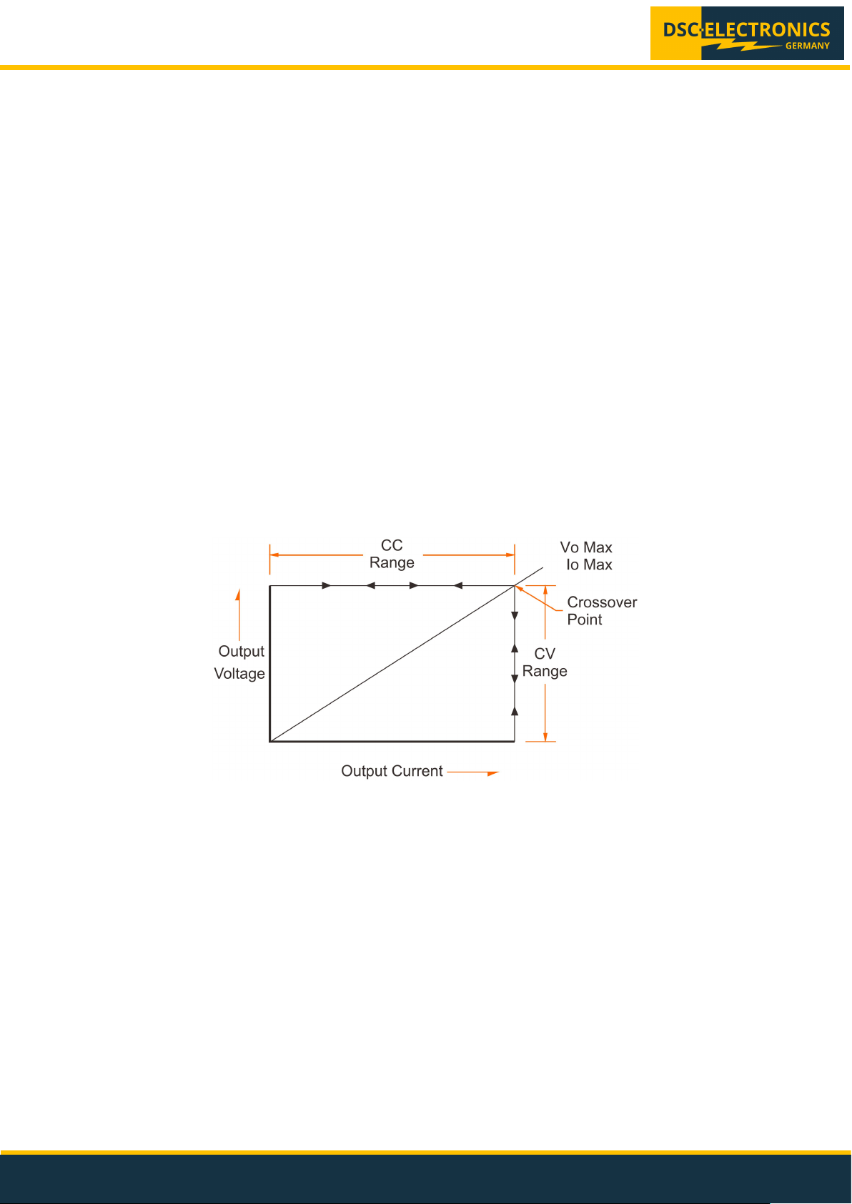
5.3 Constant current operation
NOTE: Pressing the voltage or current knob shortly switches between coarse and fine tuning.
1. Turn on the power and check that the output is off.
2. Press the SET button and set the desired voltage and current limit according to point 5.2.
4. Turn the output on by pressing the OUTPUT button.
5. The CC indicator lights up as soon as the output current reaches the current limit set.
The power supply now operates in constant current mode (CC). The output current remains stable while the voltage is
being adjusted automatically.
5.4 Locking the front panel
Press the current knob for 3 seconds to lock or unlock the front panel. The current and voltage knob as well as the
SET button are not operational when the front panel is locked.
6. Operation instructions for devices with option [Y]
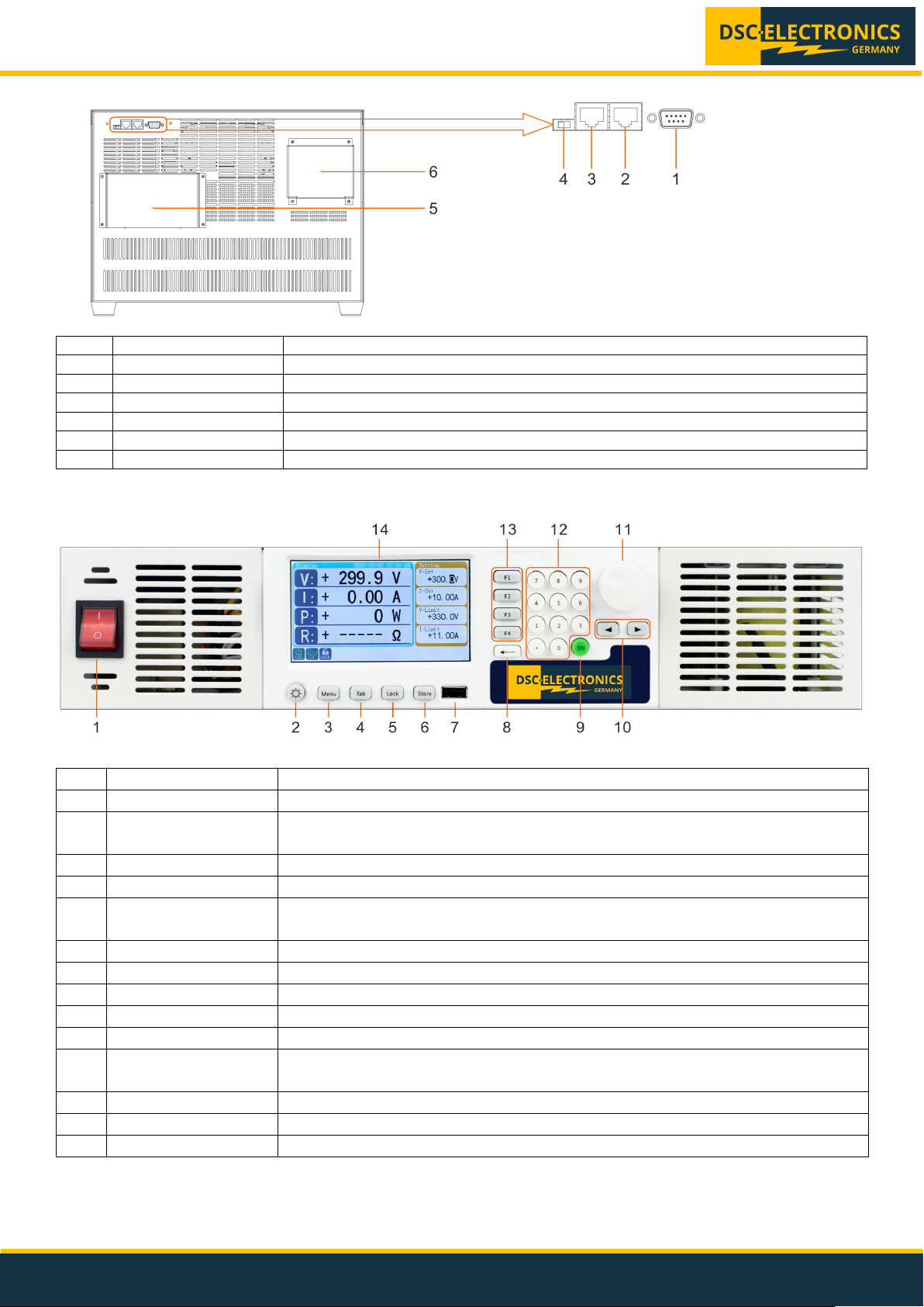
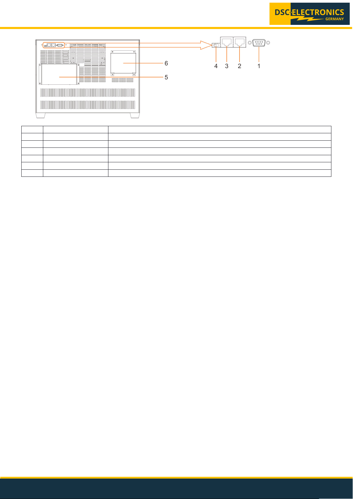
The DP-D Gen2 power supply can be optionally equipped with external analog control and feedback connections,
which allow to regulate and measure the set and real output values of the power supply externally. At the same time,
either external analog control or digital and the front panel controls can be used, thus make sure to select your desired
control method with the switch 4 on the rear panel before operation.
Caution: Always check that the output is switched off and the capacitors are discharged before connecting the load to
the power supply.
6.1 Set voltage
Press [F1] key to enter voltage setup mode (V-Set), now the cursor appears on voltage value position. The voltage
value can be set up in two ways:
- Adjust voltage value by rotary knob
- Input voltage value through the keypad
Press < > keys to move the cursor to the position that you would like to adjust, this also works with the rotary knob.
When the voltage value is adjusted to the desired value, short press the rotary knob to store the value and exit setup
mode.
6.2 Set current
Press [F2] key to enter current setup mode (I-Set), now the cursor appears on current value position. Perform the
current setup the same way as described in the voltage setup section above.
6.3 Set OVP
Press [F3] key to enter over voltage protection (OVP) limit setup mode (V-Limit). The cursor appears on voltage limit
value position. Perform the current setup the same way as described in the voltage setup section above.
6.4 Set OCP
Press [F4] key to enter over current protection (OCP) limit setup mode (I-Limit). The cursor appears on current limit
value position. Perform the current setup the same way as described in the voltage setup section above.
6.5 Set output On/Off
After power on, the power supply output status is defaulted to OFF. Output has to be turned on by pressing the on/off
key. Short press the [ON] key to turn on the output. The “ON” icon appears on the lower left corner of the LCD screen
when output is turned on. Short press the [ON] key again to turn off output. The “Off” icon appears on the lower left
corner of the LCD screen when the output is off.