Maynuo Electronic M88 Series User manual

1
USER MANUAL
M88 Series Programmable DC Power Supply
M8811/M8812/M8813/M8831/
M8851/M8852/M8853/
M8871/M8872/M8873/M8874
Version: V20121229

M88 Series Programmable DC Power Supply
2
Content
Chapter 1 Introduction ...................................................................................................................... 3
Chapter 2 Technical Specifications ................................................................................................... 4
2.1 Main Technical Specification...................................................................................................... 4
2.2 Supplemental Characteristics .................................................................................................... 7
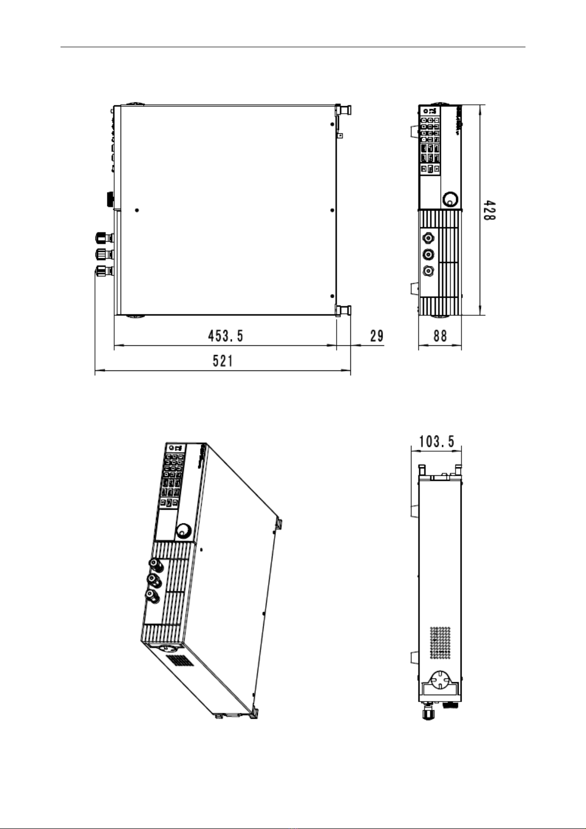
2.3 M88 Power Supply Dimension................................................................................................... 7
Chapter 3 Quick Start ..................................................................................................................... 10
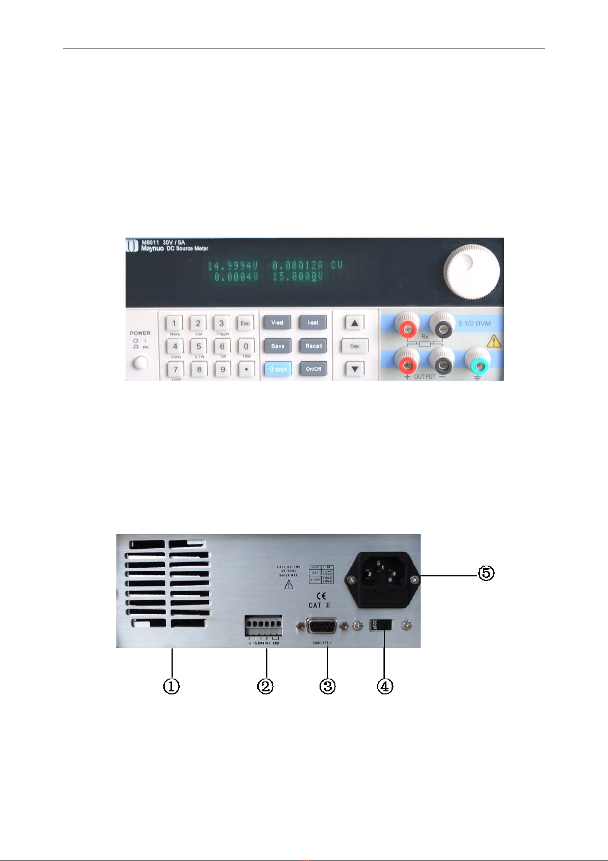
3.1 Front Panel and Rear Panel .................................................................................................... 10
3.2 Preliminary Checkout............................................................................................................... 11
3.3 If the Power Supply Does Not Turn On.................................................................................... 11
3.4 How to Adjust the Carrying Handle .......................................................................................... 12
3.5 How to Rackmount the Instrument........................................................................................... 12
Chapter 4 Panel Operation ............................................................................................................. 14
4.1 Key Layout............................................................................................................................... 14
4.2 Front-panel Operation Overview.............................................................................................. 15
4.3 Constant Voltage Operation..................................................................................................... 15
4.4 Constant Current Operation..................................................................................................... 16
4.5 Saving and Recalling Operation .............................................................................................. 16
4.6 Menu Operation ....................................................................................................................... 16
4.6.1 Menu Description .............................................................................................................. 16
4.6.2 Menu Function .................................................................................................................. 19
4.7 Output On-Off Operation.......................................................................................................... 23
4.8 Remote Measurement Function............................................................................................... 23
4.9 Milliohmmeter Function............................................................................................................ 24
4.10 Voltmeter Function................................................................................................................. 25
Chapter 5 Remote Operation Mode................................................................................................ 26
5.1 M131/M132/M133 Communication Cable................................................................................ 26
5.2 Communication between Power Supply and PC ..................................................................... 28
Chapter 6 SCPI Communication Protocal....................................................................................... 30
6.1 SCPI Communication Command Introduction ......................................................................... 30
6.2 Command Introduction of M88 Power Supply ......................................................................... 31
6.2.1 Basic command (IEEE-488.2 Common Command Set).................................................... 31
6.2.2 System Command............................................................................................................. 31
6.2.3 Measurement Command................................................................................................... 32
6.2.4 Setting Command ............................................................................................................. 33
6.2.5 List Operation Related Command ..................................................................................... 36

Maynuo Electronic Co., Ltd
3
Chapter 1 Introduction
M88 series power supply is high performance single-output programmable DC power supply with
communication interface, possessing the character of fast rise time speed (The rise speed of M8811
power supply can be less than 10mS and the M8851 can be less than 20mS). The combination of
bench-top and system features in M88 power supplies provides versatile solutions for your design and
test requirements. The M88 series can not only be programmed through the keyboard on the panel,
but also be functioned as voltmeter and milliohmmeter, which will bring great convenience to the
users. As a regeneration product of ordinary programmable power supplies, M88 series power supply
is more cost-effective.
M8831 power supply, a new generation of programmable linear power supply, are designed with high
speed dynamic programming output(Voltage 0-30V, 1ms rising time), high current accuracy (0.001mA
resolution) and low internal resistance, which can satisfy all the test requirements. Meanwhile, the
voltage level switch works without relay, which will cause the fast switch between high voltage and low
voltage. Moreover, M8831 power supply provides the best solutions for cellphone research,
micro-electronics lab,research institue and special users requiring power supply with low current
buthigh accuracy.
Features
¾Low ripple and noise
¾High resolution and accuracy (0.1mV/0.01mA, M8831 reaches up to 0.001mA)
¾Built-in a high-accuracy 5 1/2 voltmeter and milliohmmeter
¾Supporting high-accuracy and dynamic programming output
¾High-luminance VFD screen and two lines& four ways display
¾Smart fan will be automatically initiated according to the temperature
¾Supporting remote voltage compensation and multidata storage
¾Supporting external trigger input and output
¾Power-on-self-test, software calibration and standard rack mountable
¾Supporting
RS232/RS485/USB interface

M88 Series Programmable DC Power Supply
4
Chapter 2 Technical Specifications
2.1 Main Technical Specification
M881X series power supply technical specification table
Model M8811 M8812 M8813 M8831
Voltage 0-30V 0-75V 0-150V 0-30V
Output Rating
Current 0-5A 0-2A 0-1A 0-1A
Voltage <0.01%+0.5mV <0.01%+0.5mV <0.01%+0.5mV <0.01%+0.5mV
Load
Regulation Current <0.01%+0.1mA <0.01%+0.1mA <0.01%+0.1mA <0.01%+0.1mA
Voltage 0.5mV 1mV 2mV 0.5mV
Setting Value
Resolution Current 0.1mA 0.05mA 0.01mA 0.01mA
Voltage 0.1mV 0.1mV 1mV 0.1mV
Readback
Value
Resolution Current 0.01mA 0.01mA 0.01mA 0.001mA
Voltage 0.01%+2mV 0.01%+5mV 0.01%+10mV 0.01%+2mV
Setting Value
Accuracy Current 0.05%+1mA 0.05%+0.5mA 0.05%+0.1mA 0.05%+0.1mA
Voltage 0.02%+5mV 0.02%+15mV 0.02%+35mV 0.02%+5mV
Readback
Value Accuracy Current 0.1%+5mA 0.05%+2mA 0.05%+1mA 0.02%+1mA
Voltage 3mvp-p 5mvp-p 10mvp-p 10mvp-p
Ripple
Current 2mA rms 1mA rms 0.5mA rms 0.5mA rms
Voltmeter
Accuracy
0-12V Accuracy: 0.02%+2mV
0-58V Accuracy: 0.02%+5mV
Milliohmmeter
Accuracy
10W. 0-1000mΩAccuracy: 0.2%+3mΩ
1000-10000 mΩAccuracy: 0.2%+6mΩ
Working
Condition 0-40°C; 0-90%RH
Power Required AC 120V/220V±10%; 50/60HZ
Weight 6.5Kg
Dimension 214mmW x 101.5mmH x 365mmD

Maynuo Electronic Co., Ltd
5
M885X series power supply technical specification table
Model M8851 M8852 M8853
Voltage 0-6V 0-30V 0-75V
Output Rating
Current 0-60A 0-20A 0-8A
Voltage <0.01%+1mV <0.01%+1mV <0.01%+1mV
Load Regulation
Current <0.01%+0.1mA <0.01%+0.1mA <0.01%+0.1mA
Voltage 0.1mV 0.5mV 1mV
Setting Value
Resolution Current 1mA 0.5mA 0.2mA
Voltage 0.1mV 0.1mV 0.1mV
Readback Value
Resolution Current 0.1mA 0.1mA 0.1mA
Voltage 0.01%+1mV 0.01%+5mV 0.01%+10mV
Setting Value
Accuracy Current 0.05%+6mA 0.05%+2mA 0.05%+1mA
Voltage 0.02%+2mV 0.02%+5mV 0.02%+15mV
Readback Value
Accuracy Current 0.05%+45mA 0.05%+20mA 0.05%+8mA
Voltage 3mvp-p 5mvp-p 7mvp-p
Ripple
Current 15mA rms 7mA rms 4mA rms
Voltmeter Accuracy 0-12V Accuracy: 0.02%+2mV
0-58V Accuracy: 0.02%+5mV
Milliohmmeter
Accuracy
10W. 0-1000mΩAccuracy: 0.2%+3mΩ
1000-10000 mΩAccuracy: 0.2%+6mΩ
Working Condition 0-40°C; 0-90%RH
Power Required AC 120V/220V+10%; 50/60HZ
Weight 28Kg
Dimension 428mmW×88mmH×453.5mmD

M88 Series Programmable DC Power Supply
6
M887X series power supply technical specification table
Model M8871 M8872 M8873 M8874
Voltage 0-15V 0-30V 0-75V 0-100V
Output Rating
Current 0-60A 0-35A 0-15A 0-11A
Voltage <0.01%+1mV <0.01%+1mV <0.01%+1mV <0.01%+1mV
Load Regulation
Current <0.01%+0.1mA <0.01%+0.1mA <0.01%+0.1mA <0.01%+0.1mA
Voltage 0.1mV 0.5mV 2mV 2mV
Setting Value
Resolution Current 1mA 0.5mA 0.2mA 0.2mA
Voltage 0.1mV 0.1mV 0.1mV 1mV
Readback Value
Resolution Current 0.1mA 0.1mA 0.1mA 0.1mA
Voltage 0.01%+1mV 0.01%+5mV 0.01%+10mV 0.01%+15mV
Setting Value
Accuracy Current 0.05%+6mA 0.05%+2mA 0.05%+1mA 0.05%+1mA
Voltage 0.03%+3mV 0.03%+5mV 0.03%+15mV 0.03%+25mV
Readback Value
Accuracy Current 0.05%+45mA 0.05%+25mA 0.05%+12mA 0.05%+10mA
Voltage 4mvp-p 5mvp-p 6mvp-p 8mvp-p
Ripple
Current 15mA rms 8mA rms 3mA rms 2.5mA rms
Voltmeter
Accuracy
0-12V Accuracy: 0.02%+2mV
0-58V Accuracy: 0.02%+5mV
Milliohmmeter
Accuracy
10W. 0-1000mΩAccuracy: 0.2%+3mΩ
1000-10000 mΩAccuracy: 0.2%+6mΩ
Working
Condition 0-40°C; 0-90%RH
Power Required AC 125V/220V+10%; 50/60HZ
Weight 45Kg
Dimension 482mmW×184.5mmH×531mmD

Maynuo Electronic Co., Ltd
2.2 Supplemental Characteristics
¾State storage memory: 50 user-configurable stored states
¾Recommended calibration interval: 1 year
¾AC input ratings (selectable via switch on the rear panel)
¾Option Opt.01: 220VAC ± 10%, 47 to 63 Hz
¾Option Opt.02: 110VAC ± 10%, 47 to 63 Hz
¾Cooling: forced cooling
¾Operating temperature: 0 to 40 °C
¾Storage temperature: -20 to 70 °C
¾Environmental conditions: designed for indoor use installation categoryⅡ, pollution degree 2
environment. Designed to operate at maximum relative humidity of 90%
2.3 M88 Power Supply Dimension
The dimension of M881X/M8831 series is 214mm W x 101.5mm H x 365mm D.
Diagram 2.1 M881X/M8831 Power Supply Dimension
7

M88 Series Programmable DC Power Supply
The dimension of M885X Series is 428mm W×88mm H×453.5mm D.
Diagram 2.2 M885X Power Supply Dimension
8

Maynuo Electronic Co., Ltd
The dimension of M887X series is 482mm W×184.5mm H×531mm D.
Diagram 2.3 M887X Power Supply Dimension
9

M88 Series Programmable DC Power Supply
Chapter 3 Quick Start
This chapter mainly focuses on the brief introduction of the surface appearance and basic functions of
M88 series power supply so that both experienced and inexperienced users can be acquainted with
the new products quickly. Meanwhile, the chapter also clarifies some preliminary checkout that should
be made prior to operation to make sure the normal running of the products.
3.1 Front Panel and Rear Panel
The front panel layout of M881X series power supply is as follows:
Diagram 3.1 the Front Panel of M881X Series Power Supply
zThe upper half is black VFD display screen and knob
zThe bottom half, left side to right side, is numberic keys 0-9, esc key, function keys, up-down
keys, enter key, input terminall and output terminal
The rear panel layout of M881X is as follows:
Diagram 3.2 the Rear Panel of M881X Series Power Supply
①cooling window
②multifunction connector (remote sensing connector, trigger connector and GND connector)
③9-pin serial port interface connector
④line voltage selection switch (110 VAC or 220 VAC)
10

Maynuo Electronic Co., Ltd
⑤AC input connector
3.2 Preliminary Checkout
The following steps help you verify that the power supply is ready for use.
1. Check the list of supplied items
Verify that you have received the following items with your power supply. If anything is missing,
contact your nearest sales office.
zOne power cord for your location
zThe user’s manual
zOne CD (only when you have bought communication accessories)
zOne communication cable (only when you have bought communication accessories)
zOne test line (only M8811 ,M8812 ,M8813, M8831 have the test line)
2.Connect the power cord and turn on the power supply
When you turn on the power supply, the VFD display screen will light up briefly and the power supply
performs its power-on self-test. Please check if there is any stroke loss on VFD display.
Warning:Your power supply is equipped with a 3-wire grounding type power cord. The
power supply is grounded only when the power-line cord is plugged into an appropriate
receptacle. Do not operate your power supply without adequate cabinet ground connection.
3.3 If the Power Supply Does Not Turn On
Use the following steps to help solve problems you might encounter when turning on the instrument.
1. Verify that there is AC power to the power supply.
First, verify that the power cord is firmly plugged into the power receptacle on the rear panel of the
power supply. You should also make sure that the power source you plugged the power supply into is
energized. Then, verify that the power supply is turned on.
2. Verify the power-line voltage setting.
The line voltage is set to the proper value for your country (110VAC or 220VAC) when the power
supply is shipped from the factory. Change the voltage setting if it’s not correct.
3. Verify that the correct power-line fuse is installed.
If the fuse was damaged, please see the table below to replace the fuse for your power supply.
Model Fuse Description(110VAC)Fuse Description(220VAC)
M8811 T5A 250V T3.15A 250V
M8812 T5A 250V T3.15A 250V
11

M88 Series Programmable DC Power Supply
M8813 T5A 250V T3.15A 250V
M8831 T5A 250V T3.15A 250V
M8851 T10A 250V T6.3A 250V
M8852 T10A 250V T6.3A 250V
M8853 T10A 250V T6.3A 250V
M8871 T15A 250V T10A 250V
M8872 T15A 250V T10A 250V
M8873 T15A 250V T10A 250V
M8874 T15A 250V T10A 250V
4. How to replace the power-line fuse
Open the plastic cover which locates at below the power input socket in the rear panel of the power
supply by screwdriver, then you will see the fuse. Please replace the damaged fuse with the matched
fuse.
3.4 How to Adjust the Carrying Handle
To adjust the position, grasp the handle by the sides and pull outward. Then, rotate the handle to the
desired position. There are following three positions for you to choose:
Diagram 3.3 M88 Series Power Supply Viewing Positions
3.5 How to Rackmount the Instrument
The power supply can be mounted in a standard 19-inch rack cabinet and be easily applied to your
testing system. If you want to rackmount the M88 Series, please buy M151 rack kit.
Note:Remove the carrying handle and the rubber coating on the front panel before rackmounting the
instrument.
12

Maynuo Electronic Co., Ltd
Diagram 3.4 to Rackmount a Single Instrument
Diagram 3.5 to Rackmount two Instruments Side by Side
13

M88 Series Programmable DC Power Supply
Chapter 4 Panel Operation
This chapter mainly introduces the front-panel operation in detail from the following parts:
zKey Layout
zThe Front Panel Operation Overview
zVoltage Set Operation
zCurrent Set Operation
zSaving and Recalling Operation
zMenu Operation
zOutput ON/OFF Operation
zRemote Measurement Function
zMilliohmmeter Function
zVoltmeter Function
4.1 Key Layout
Function Keys
Multifunction Keys
Diagram 4.1 Operation Panel
Multifunction Keys Description
0~9 Numberic keys
Menu Menu operation key
List List output operation
Trigger Trigger key
V/mΩVoltmeter and milliohmmeter switch button
0.1W Choose 0.1W power output operation when the instrument is used as an milliohmmeter
1W Choose 1W power output when the instrument is used as an milliohmmeter
10W Choose 10W power output when the instrument is used as an milliohmmeter
Local Local operation
Esc Esc key (can be exited from any working condition)
14

Maynuo Electronic Co., Ltd
Function Keys Description
15
Set the voltage value
V
-
set
Set the current value
I
-
set
Save the current settings to a specified storage location
Recall the saved settings from a specified storage location
Save
Menu operation: set the parameter of the power supply
Recall
On/Off
Control the output on/off state
M
enu
Used together with the multifunction keys to perform diversity functions and
applications(for example: shift+Menu can perform menu function)
Shift
Up-key: choose menu item in menu operation or to increase the output voltage
▲
▼Down-key: choose menu item in menu operation or to reduce the output voltage
Enter the selected value or setting
Enter
4.2 Front-panel Operation Overview
The following section describes an overview of the front-panel keys before operating your power
supply.
zThe power supply is shipped from the factory configured in the front-panel operation mode.
At power-on, the power supply is automatically set to operate in the front-panel operation
mode. When in this mode, the front panel keys can be used.
zWhen the power supply is in remote operation mode, you cannot use the front-panel. A
change between front-panel and remote operation modes will not result in any change in
the output parameters. You can change the front-panel and remote operation modes by PC.
zThe output of the power supply can be enabled or disabled from the front panel by pressing
the key
On/Off
.
zThe VFD display shows the current operating status of the power supply with annunciators.
When it is powered on, the VFD will display two lines of data. The first line shows the actual
voltage value, actual current value and power supply’s status while the second line shows
the voltage value that can be measured by voltmeter and output setting value of the power
supply.
4.3 Constant Voltage Operation
The constant voltage range is from 0V to the maximum voltage value of each model. It is very easy for
you to set the constant voltage output. You have 2 solutions to set the constant voltage value.
Solution 1:
Press the ▲and ▼keys to change the value when the M88 series power supply is powered on.
Solution 2:
Step1. Power on the M88 series instrument
Step2. Press key
V-Set
Step3. Press the numeric keys to to enter the voltage value you wanted
9
0

M88 Series Programmable DC Power Supply
Step4. Press to confirm the value
Ente
r
When you close Knob Lock function in Config menu, the following two operations also can be used:
1) Use upper revolving encoder directly to adjust voltage;
2) Press key then use upper revolving encoder to adjust voltage
V-Set
4.4 Constant Current Operation
The constant current output range is from 0 A to the maximum current value of each type. It is very
easy for you to set the constant current output.
Step1. Power on the M88 series instrument
Step2. Press key
I-Set
Step3. Use the numeric keys to to enter the voltage value you wanted
9
0
Step4. Press key to confirm the value
16
If you close knob lock function in config menu, please use following operation:
Ente
r
Press key then use upper revolving encoder to adjust voltage
I-Set
4.5 Saving and Recalling Operation
You can store up to 50 different output states in storage register locations(0~49) so that you can recall
the saved settings quickly. This kind of store operation can be performed by the keys
Save
and
Recall
located in the front panel. When the fast recalling is activated, you can press the numberic
keys to to invoke the corresponding data.
9
0
Each output state includes: 1. Constant voltage value, 2.Constant current value, 3.Maximun voltage
setting value, 4. Step voltage value.
After you setting an output state (CV value, CC value and Maximum voltage), press the key
Save
and the numeric keys to to store the output value in a specified memory location.
Press the key and the numeric keys to to recall the output value from a specified
memory location.
9
0
9
Recall 0
4.6 Menu Operation
4.6.1 Menu Description
MENU
Press the key to access to the menu function and at the moment the VFD display screen
shows the menu items. You can select the menu items by pressing the ▲and ▼keys or by rotating
the knob, and then press the key to enter in the menu item you wanted. Or you can press
the key to get back to the higher level men
ENTER
u.
Esc
The first level menu includes:
Config: set the function of power supply
System set: set the system parameter
List Set: set list operation
Auto test: set auto test operation

Maynuo Electronic Co., Ltd
Output Timer: set the duation of output
SN: the serial number of the power supply
Exit: exit the first-level menu
When accessing to Config item, the following menu items will be displayed on the VFD display
screen by pressing the keys ▲and ▼.
Init: set all settings to factory default set
Out Memory: set the power supply’s output state when it is powered on
On Setting the same state as last time you turned
off the power supply.
17
Off(Default) Setting the output to OFF state when the power
supply is powered on.
TRI KeepOut: set TRI as preseved output port
On When TRI is in low voltage level, the output
state of power supply is ON.
When TRI is in high voltage level, the output
state of power supply is OFF.
When the TRI KeepOut is enabled, the ON/OFF
on the front panel is invalid.
The TRI Keepout is only valid to ordinary
operation mode. It is invaid to list opeartion and
auto test mode.
Off(Default) Disabled
Fast Recall: set key shortcut function
On In the main interface (not enter any menu of the
power supply), press the key 0~9 to recall
the parameters set by Save function
Off(Default) Disabled
Key Sound: set the key sound
On(Default) The buzzer will sound when any key was
pressed.
Off The buzzer will not sound when any key was
pressed
Knob Lock: set the knob lock state
On The knob is locked and rotating the knob will not
cause any change of the setting value.
Off(Default) The knob is unlocked and rotating the knob will
cause change of the setting value.
Remote Sense: set the remote sense mode
On Activating the remote sense mode ( Rear-panel
measurement mode)
Off(Default) Activating the front-panel measurement mode
Curr Unit: set the unit of current

M88 Series Programmable DC Power Supply
mA Set the unit of current is mA
A(Default) Set the unit of current is A
Match Power: set the matching power
50 HZ(Default) Match 50HZ
60 HZ Match 60HZ
Baudrate Set: set the baud rate
4800 Setting the baudrate as 4800bps
9600(Default) Setting the baudrate as 9600bps
19200 Setting the baudrate as 19200bps
38400 Setting the baudrate as 38400bps
Comm. Parity: set the communication parity
None(Default) Setting no parity bit
Setting comm. parity as even parity bit
Even
Setting comm. parity as odd parity bit
Odd
Key Lock Set: set the key lock and password function
When set the password as 0 or pressing the
key Enter directly, the Key Lock Set is
disable.
When the Key Lock Set is enable, the Key
Lock Set get locked if no keyboard operation
within 60 seconds, the Key Lock Set gets
enable only if you input the correct
password.
Password=
Exit: exit from the current menu
When accessing to System Set item,the following menu items will be displayed on the VFD display
screen by pressing the keys ▲and ▼.
Max Volt: set the maximum voltage of the power supply
Max Volt= Setting the maximum voltage
Step Volt: set the step voltage
After the step voltage set, the voltage value
increases or discreases equal to each step
voltage by pressing the key ▲or ▼once.
Step=
Exit: exit from the current menu
When accessing to the List Set item, the following menu items will be displayed on the VFD display
screen by pressing the keys ▲and ▼.
Load List File: read list file
18

Maynuo Electronic Co., Ltd
Edit List File: edit list file
Continuous Continuous mode, start from the first step to
the last step.
Loop Mode Loop mode, repeatedly execute the steps in
accordance with the order of the list.
Step Mode Step mode, execute single step for one
trigger.
Edit File Format: format file in list operation
1X200 Steps Set list file as 1X200 step
2X100 Steps Set list file as 2X100 step
4X50 Steps Set list file as 4X50 step
8X25 Steps Set list file as 8X25 step
Exit: exit from the current menu
When accessing to the Auto Test item, the following menu items will be displayed on the VFD display
screen by pressing the keys ▲and ▼.
Load Atest File: read auto test file
Edit Atest File: edit auto test file
Exit: exit the auto test menu
When accessing to the Output Timer item, you can see the item Close Delay, which means to set
the output timing.
Close Delay:set the duration of the output
The unit of the Close Delay is second, the accuracy is 0.001 second;The output switch to OFF
state when the duration is over.
The function is disable when the duration is set 0 second. The disable state is the defualt state.
The function is invaild when the TRI KeepOut is used in ordinary working modes.
When accessing to the SN item, the 18 digits serial number shows on the VFD display.
For example: SN= 080010960121229001
Note: When accessing to the Menu item, you can press or Exit to exit the menu operation.
19
No matter which function the instrument is performing, you can exit the function operation
status by pressing the key . .
Esc
Esc
4.6.2 Menu Function
The output state setup after the intrument powered on (>Out Memory)
This instruction is used to set the output state when the power supply is powered on. If you select the
item On, the power supply will set the output to OFF state when the power supply is powered on. If

M88 Series Programmable DC Power Supply
you select the item Off, the output will remain the same state as last time you turned off the power
supply.
Setting the Key Sound (Key Sound)
This instruction can switch on/off the buzzing sound when you press any key, If you select the item On,
the buzzer will sound when any key was pressed. If you select Off, the buzzer will not sound when the
keys were pressed. Default setting is the item On; the buzzer will sound when you press any key.
Setting the Baudrate (>Baudrate Set)
This instruction can change the communication baud rate of the power supply; the baud rate range is
4800bps, 9600bps, 19200bps, 38400bps. Before the communication, you must make sure that there
is same baud rate between the power supply and the computer. Default baud rate is 9600bps.
Setting Password for Function Keys (>Key Lock Set)
This instruction can set a password (1 through 8 digits) to lock the function keys operation. After
setting the password, the key V-Set,Save,Recall,Menu will be locked if no operation on keyboard in
60 seconds. Only if you put the correct password, the above keys are able to unlock. If you don’t want
to lock the function keys, please don’t press any number key or just put 0when you enter the Key
Lock Set item, just press
Enter
key to unlock it.
List Operation (>List Set)
You can set every single-step value and duration time by new list operation so as to get different
output list. The parameters of the list operation include the name of the list file which are input, input
single step numbers (200steps at most), single step duration time (1mS at least) and the setting value
of every single step.
When list operation is under Continuous mode, the power supply will begin the list operation until the
list operation is finished or until receiving the next trigger signal.
Before editing the list, if you want to change the file storage format, please operate as the following
steps:
20
1) Press the keys
Shift
and Menu to access to the menu function.
2) When VFD display screen shows the item Menu Config, press the key ▼twice to select the item
List Set, press the key
Enter
to confirm.
3) When VFD display screen shows the item Load ListFile, Press the key ▼twice, select the item
Edit File Format, press the key
Enter
to confirm.
4) When VFD display screen shows 8*25 Steps, Press the key ▼, select a list mode you want from
1*200 Steps,2*100 Steps, 4*50 Steps, press the key
Enter
to confirm.
1*200 steps means to set list file as 1X200 step
2*100 steps means to set list file as 2X100 step
Other manuals for M88 Series
1
This manual suits for next models
11
Table of contents
Other Maynuo Electronic Power Supply manuals