Brasch GDCP-Touch User manual

GDCP-Touch
Installation / Operation Manual
Brasch Environmental Technologies, LLC
40 Long Road, Suite 0
Chesterfield, Missouri 63005
3 4-29 -0440
www.braschenvtech.com

Table of Contents
Introduction...................................................................................................................................5
General Description..................................................................................................................5
Features and Benefits..............................................................................................................6
Technical Specifications................................................................................................................7
Product Specifications..............................................................................................................7
Target Gas Specifications.........................................................................................................8
Carbon Monoxide.................................................................................................................8
Nitrogen Dioxide...................................................................................................................8
Operation Safety Notice................................................................................................................9
Types of Notices.......................................................................................................................9
Quick Start Guide....................................................................................................................... 0
Step – Mounting.................................................................................................................. 0
Step 2 – Input Wiring.............................................................................................................. 0
Step 3 – Remote Transmitter Wiring......................................................................................
Step 4 – Relay Wiring.............................................................................................................
Step 5 – External Alarms........................................................................................................ 2
Step 6 – Applying Power........................................................................................................ 2
Step 7 – Testing the System................................................................................................... 2
Installation................................................................................................................................... 3
Mounting the Control Panel.................................................................................................... 3
Mounting the Transmitters...................................................................................................... 3
Connecting the Power Supply................................................................................................ 5
Connecting the Remote Transmitters..................................................................................... 6
Connecting the Ventilation System......................................................................................... 7
Connecting the External Alarm............................................................................................... 8
Connecting the Voltage or Current Proportional Output........................................................ 8
Applying Power For the First Time......................................................................................... 8
Performing a System Test...................................................................................................... 9
Typical Installation Diagrams..................................................................................................20
Operation....................................................................................................................................23
How the Transmitter Senses the Target Gas.........................................................................23
How the Panel Controls the Ventilation Equipment...............................................................23
Sensors..............................................................................................................................23
Relays................................................................................................................................23
Zones..................................................................................................................................24
Overrides............................................................................................................................24
Analog Output....................................................................................................................24
Modbus Output...................................................................................................................24
BACnet IP Output...............................................................................................................24
Navigating the User Interface.................................................................................................25
Home Screen.....................................................................................................................25
Zone Screen.......................................................................................................................26
IOM03
Rev . – May 8, 202 2

Relay Screen......................................................................................................................26
Passcode Entry Screen......................................................................................................27
Settings Menu....................................................................................................................27
Factory Default Settings.........................................................................................................28
Adjusting the Hardware Settings............................................................................................29
Changing the Sensor Address...........................................................................................29
Changing the Relay Board Address...................................................................................29
Changing the Analog Output Scale....................................................................................29
Adjusting the Software Settings.............................................................................................30
Adding/Removing Sensors.................................................................................................30
Adding/Removing Relays...................................................................................................30
Adding/Removing Zones....................................................................................................3
Adjusting the Setpoints......................................................................................................3
Adjusting the Delays..........................................................................................................32
Adjusting the Activation Type.............................................................................................32
Adjusting the Zone Display Type........................................................................................33
Assigning Sensors.............................................................................................................33
Assigning Relays................................................................................................................34
Assigning Analog Outputs..................................................................................................34
Changing Relay Levels......................................................................................................35
Setting Manual Overrides...................................................................................................36
Setting Automatic Overrides...............................................................................................37
Changing the Date and Time.............................................................................................37
Configuring BACnet...........................................................................................................38
Performing a Reset............................................................................................................38
Using the Analog Outputs.......................................................................................................39
Obtaining the Best Operation.................................................................................................40
Carbon Monoxide and/or Nitrogen Dioxide Transmitters...................................................40
Maintenance...............................................................................................................................4
Testing the Response to the Target Gas................................................................................4
Carbon Monoxide and/or Nitrogen Dioxide Transmitters...................................................4
Replacing the Sensor.............................................................................................................42
Suggested Repair Parts.........................................................................................................43
Troubleshooting..........................................................................................................................44
Error Messages......................................................................................................................44
Relay # – Manual Override Active......................................................................................44
Sensor # Communication Loss..........................................................................................44
Sensor # – Calibration Expired..........................................................................................44
Sensor # End of Life – Please Replace.............................................................................44
Sensor # Sensor Missing...................................................................................................45
Sensor # Calibration Invalid...............................................................................................45
Relay Board # Communication Loss..................................................................................45
Insert SD Card....................................................................................................................45
SD Write Error – Replace SD Card....................................................................................45
Checking and Replacing the Battery......................................................................................46
IOM03
Rev . – May 8, 202 3

Checking and Replacing Fuses..............................................................................................46
Common Installation/Operation Mistakes..............................................................................47
Ventilation Components Connected to the Wrong Relays.................................................47
Relay Levels Set Incorrectly...............................................................................................47
Improper Communication Wiring.......................................................................................47
Setpoint Level Set at Wrong Concentration.......................................................................47
Delay Period Set Incorrectly...............................................................................................48
Setting the Proportional Output Incorrectly........................................................................48
Bias/Termination Switches in the Wrong Position..............................................................48
Relay Activation Type Set Incorrectly.................................................................................49
Panel Not Grounded..........................................................................................................49
Transmitter Mounted in an Unsatisfactory Location..........................................................49
Limited Warranty.........................................................................................................................50
Warranty Statement...........................................................................................................50
Service and Repair Procedures.........................................................................................50
Appendix.....................................................................................................................................5
Models and Descriptions........................................................................................................5
Transmitter Model and Description....................................................................................5
Accessory Model Number and Description........................................................................5
Figures and Diagrams............................................................................................................52
IOM03
Rev . – May 8, 202 4

Introduction
General Description
The Brasch Environmental Technologies GDCP-Touch Gas Detector Control Panel is designed
to function as a complete ventilation control system. These systems can be as simple as a
panel and one transmitter controlling one ventilation fan, or as complex as a panel with 28
sensors controlling 32 zones worth of ventilation equipment.
The control panel itself consists of a touchscreen display, a relay control board, and digital
control circuitry. The panel monitors the signal from the transmitters, compares the signal to
preset values, and controls relay contacts based upon the comparison. These relay contacts
then provide signals that control ventilation components such as exhaust fans, louvers, and
dampers. The touchscreen provides a visual indication of the system’s operational condition
along with an intuitive interface for configuring the entire system. A linear proportional output is
also included for communication with a building management system (BMS), direct digital
controls system (DDCS), or variable-frequency drive (VFD).
The sensors used in the remote transmitters operate on the electrochemical principle and are
able to detect carbon monoxide or nitrogen dioxide. A current is produced when the target gas
reacts chemically with an electrode inside the sensor. This small current is converted to an
analog voltage, amplified, and converted to a digital signal. This signal is proportional to the
gas concentration present at the sensor and is shown on the display. After comparing the
digital signal to preset values, the panel updates the display and relays.
The GDCP-Touch housing has a NEMA 4X rating and is supplied with knockouts so that the
control panel can mount directly to a standard four inch conduit box. A hinged cover secured
by two screws makes it easy to gain access to the touchscreen for system configuration. A
secondary, interior hinge affords access to the relay board, allowing power, communication,
and relay connections to be made.
The GDCP-Touch can also accept additional relay boards in the form of GDCP-
ExpansionPacks. These provide four more relays for added control along with another analog
output and a signal repeater to extend the range and sensor capacity. GDCP-PowerPacks
may be added to convert AC line voltage to the low voltage required to power the control
panel, transmitters, and relay boards.
IOM03
Rev . – May 8, 202 5

Features and Benefits
•Limitless Possibilities
◦Fully Configurable Zones, Relays, Setpoints, Delays, and Outputs
◦Scalable System Size via Relay Expansion Packs
•Increased Control
◦On-Demand Ventilation Control by Gas Concentration, Timer Schedule, or User
Input
◦7” Full-Color LCD Touch Screen
•Maximum Detection
◦Monitors up to 28 CO and/or NO2 Sensors
◦Each Sensor Covers up to 9,000 sq. ft.
•Enhanced Durability
◦NEMA 4X Water and Dust Resistance
•Intelligent Connectivity
◦BACnet IP and Modbus RTU Communication for BMS Interfacing
•Simplified Installation
◦Customized Factory Programming and Configuration for Every Job
IOM03
Rev . – May 8, 202 6

Technical Specifications
Product Specifications
Input Power 24 VAC, 50/60 Hz, 0.75 A
Optional: 20 VAC, 50/60 Hz, 0.3 A via GDCP-PowerPack
Installation Category II (local level, over-voltage transients less than 500V)
Storage Temperature -50°C to 20°C (-58°F to 248°F)
Operating Temperature -20°C to 70°C (-4°F to 58°F)
Humidity 0% to 90% (non-condensing)
Ventilation Control Relays 25 VAC, 50/60 Hz, 5 A resistive, 250 VA inductive
Relay Capacity 4 internal, up to 32 total relays via GDCP-ExpansionPacks
Sensor Capacity Up to 30 remote sensors
Optional: Up to 28 remote sensors via GDCP-ExpansionPacks
Zone Capacity Up to 4 zones
Optional: Up to 32 zones via GDCP-ExpansionPacks
Internal Alarm 70 dB @ 0 cm, 2.9 kHz piezoelectric element
Display 7.0” LCD, 024 x 600, 5-point capacitive touch
Analog Outputs User-selectable 4-20 mA, 0.2- VDC, -5 VDC, or 2- 0 VDC
Digital Outputs BACnet IP, Modbus RTU
Alert Levels 4 levels, fully adjustable
Delay Times 0 to 599 minutes, separate settings for entrance and exit
Dimensions 8. 5” W x 9.93” H x 2.70” D (2 cm W x 25 cm H x 7 cm D)
Weight 5.0 lbs (2.27 kg)
Housing Gray, NEMA 4X, fiberglass/polycarbonate
Compliance Pending
IOM03
Rev . – May 8, 202 7

Target Gas Specifications
Remote transmitters for this control panel are available for monitoring carbon monoxide and/or
nitrogen dioxide as target gases. Regulatory agencies have determined the threshold
concentrations at which the gases become dangerous. Brasch Environmental Technologies,
LLC has designed their transmitters so that the measurement ranges for each target gas meet
the agencies’ requirements. Each target gas, for which Brasch currently produces a
transmitter, is listed below along with the relevant concentration specifications.
Carbon Monoxide
Full Scale Span: 200 PPM
Resolution: PPM
Minimum Accuracy*: ± 0% or 6 PPM
Relay Setpoints 0-200 PPM (in increments of .0 PPM)
Expected Lifespan 0 years
Recommended
Recalibration Time 2 years
Nitrogen Dioxide
Full Scale Span: 0 PPM
Resolution: 0. PPM
Minimum Accuracy*: ± 5% or 0.8 PPM
Relay Setpoints 0- 0 PPM (in increments of 0. PPM)
Expected Lifespan 0 years
Recommended
Recalibration Time 2 years
*Allowable tolerance for accuracy and repeatability criteria as defined in Annex A, Item 2 of ANSI/ISA 92.00.0 -20 0 (R20 5)
IOM03
Rev . – May 8, 202 8

Operation Safet Notice
Certain procedures and operations detailed in this manual require that specific precautions be
taken prior to beginning the procedure or operation. When precautions are required, a notice
will be printed in an appropriate location in the manual. The user is urged to read and
understand all such notices.
T pes of Notices
Three types of notices may be used in this manual to describe the severity of the situation
encountered.
WARNING: This notice indicates that conditions exist that could cause personal injury
or loss of life.
CAUTION:Conditions exist that could cause damage to the equipment or other
property.
Note: Special consideration should be given to the procedure or operation,
otherwise an unexpected operational result could occur.
IOM03
Rev . – May 8, 202 9

Quick Start Guide
Please read this entire manual before attempting to install and operate this control panel. This
guide is only intended to provide the basic steps necessary for installation and operation.
Each step will reference the portion of the manual where more complete information can be
obtained.
Step 1 – Mounting
Determine the location for mounting your panel and transmitters. The locations may be
indicated on the architectural drawing. Also, the owner or designer of the facility may be
consulted. Mounting guidelines can be found on page 3 of this manual.
Step 2 – Input Wiring
Provide a dedicated circuit at the required 24 VAC operating voltage at each panel mounting
location. Follow all national and local wiring codes. A conductor connected to earth ground
should also be provided. The circuit must include a disconnect switch located within easy
reach of the panel.
Ensure that the step-down transformer provides the correct secondary voltage and has the
necessary volt-amp rating to power each component in the system. Each control panel
requires 0.75 VA, each transmitter requires 2.4 VA, and each expansion pack requires 0.4 VA.
IOM03
Rev . – May 8, 202 0
WARNING
This control panel may require the use of voltage levels high enough to cause fatal injuries.
Proper procedures must be followed any time work is performed on this unit.
Only qualified personnel should attempt to install, maintain, or service this equipment.
CAUTION
Operating these devices with the incorrect voltage and power requirements can cause
internal electrical components to overheat and fail. Operation with the wrong power
requirement will void the manufacturer’s warranty and the installer will be responsible for any
damage that occurs.
Contact Brasch Environmental Technologies, LLC before connecting power to the control
panel or transmitters if you are unsure of the correct power requirement.

Connect the incoming power conductor to 8-24VAC, the return conductor to 8-24RET, and
the ground conductor to the green screw.
Refer to page 5 for further information.
Step 3 – Remote Transmitter Wiring
The control panel does not supply power to the remote transmitters. However, power may be
daisy chained through the control panel to the transmitters. Use a two-conductor cable with
color-coded conductors of at least 8 AWG to connect the power. Use a shielded, twisted-pair
cable with color-coded conductors of at least 24 AWG to connect communication. A single
four-conductor cable may be used but will reduce the maximum distance the system can
cover. See figure 0 on page 53 for details. If possible, choose cables with color-coded
conductors that follow the suggested color scheme listed on the drawings.
The transmitters will be shipped with four color-coded wires exiting the top of the housing
through a conduit fitting. If you have chosen color-coded conductors that match the wire
colors, connect the cable conductors to the wires of the same color. If your cable conductors
do not match the wire colors, assign a cable conductor color to each wire and make a list of
this assignment. Follow this color assignment when connecting any other transmitters in the
system. All transmitters share the same conductors back to the panel. Therefore, a four-
conductor cable can be connected from transmitter to transmitter, or from transmitter to panel,
as the situation dictates. Follow the wiring diagrams on page 2 and 22 to determine the
proper connections at the panel.
Step 4 – Rela Wiring
The relay board inside the control panel has four relays with connections for both normally
open (NO) and normally closed (NC) operation. These connection points are labeled on the
IOM03
Rev . – May 8, 202
CAUTION
It is very important that the power and signal connections between each transmitter and
between the transmitters and the control panel be correct. If the connections are wired
incorrectly, damage to both the transmitters and the control panel will occur.
Use a cable with color-coded conductors and make sure that the same conductor connects
to the same terminal on each transmitter and the control panel.
Do not apply power to the transmitter or control panel unless you are sure that the
connections are correct.

silkscreen next to the terminal blocks as well as in the diagram on page 54. The relay state is
labeled for the physical state of the relay when the control panel is not powered. In the default
configuration, all relays will operate independently of one another. To use multiple-speed fans,
you will need to assign different relay levels in the settings and invert the wiring connections to
avoid damaging ventilation equipment.
Do not exceed the specified voltage and power limits of the relays (see page 7). Most
installations require motor starters or larger relays to provide the necessary power
requirements for the ventilation components.
For more information concerning ventilation system operation, read page 7 of this manual.
Step 5 – External Alarms
Determine if the installation requires an external alarm. If so, provide the proper wiring and
connect the wires to the required voltage source. Any relay may be used to trigger an external
alarm. To synchronize the internal control panel alarm with external alarms, make sure the
setpoints and delay times are the same in both the Zone Settings Screen and Relay Settings
Screen.
Refer to page 8 for more information concerning the alarm feature.
Step 6 – Appl ing Power
Once you are sure that the wiring connections are correct, apply power to the control panel
circuit. When power is first applied to the transmitters, they will begin a 50 second warm-up
period. During this time, the control panel will display “--” in place of gas concentration values
on the Zone Screen and Relay Screen. Once the warm-up has finished, the gas concentration
values will appear.
See page 8 for more information concerning the initial startup.
Step 7 – Testing the S stem
The manual overrides on this control panel can be used to open and close the relays to verify
that ventilation and warning equipment is connected properly. This feature can be accessed
from the individual Relay Settings screens.
Page 9 contains a more complete procedure for testing the system.
At this point, the control panel and transmitters are now ready to monitor for the presence of
the target gas(es) and control the ventilation system to efficiently remove the gas from the
protected area.
IOM03
Rev . – May 8, 202 2

Installation
Mounting the Control Panel
The control panel is the central hub for monitoring and controlling all of the transmitters.
However, it does not necessarily need to be mounted in a centralized location. It should be
mounted indoors in a dry location where authorized users will have easy access and the
display can be easily read. Avoid placing the control panel in areas that might need to be
evacuated during a high-gas alarm condition.
The control panel is attached in the mounting position in one of two ways.
•Attach the housing to a four inch conduit box using standard ½” conduit fittings. If you
use this method, make sure that the four inch box is securely attached with screws to a
solid support base. Firmly tighten the threaded nuts on the conduit fittings so they will
not loosen over time.
•Attach the housing to a solid support base using screws through the holes in the
mounting feet.
Find a flat area at least 8 inches wide by inches tall and place the back of the
housing flat against it. Using a pencil or other slender marking tool, mark the location of
the four mounting holes using the housing as a template. Start the screws without the
housing in place to avoid any possibility of damage to the housing. Remove the screws,
place the housing in position, and install the mounting screws. Do not over-tighten the
screws as this may crack the plastic housing.
Mounting the Transmitters
The ability of the transmitters to sense the target gas and efficiently control the ventilation
system depends greatly upon proper selection of the mounting location. A transmitter monitors
the area around it by sampling the air that passes by the sensor. Since the sensor is mounted
inside a housing, air must diffuse through the intake vents and pass by the sensor on its way
out the exhaust vents. Therefore, the transmitter should be positioned where it can sample air
that contains a target gas concentration representative of the average value in that area.
When determining the mounting location, give special consideration to the following guidelines.
•Use one sensor per target gas for each area to be covered.
•Always prioritize locations with the highest occupation density.
IOM03
Rev . – May 8, 202 3

•Do not locate any transmitter further than 4000 feet from a control panel or expansion
pack.
•The types of gases each unit is designed to monitor have densities approximately equal
to that of air. For maximum safety, mount the unit at the average breathing height –
approximately 5 to 7 feet from the floor.
•Avoid mounting locations that would not be representative of the average gas value in
that area. These include but are not limited to locations near doorways, fans, ventilation
inlets and outlets, and areas with air velocities in excess of 3.3 ft/s ( m/s).
•Avoid locations that would allow direct contact with water. Mounting the unit near
outside garage doors may allow rain to hit the unit when the door is open.
•Avoid locations that are directly in the outlet air vents of heaters or air conditioners.
•Avoid mounting locations with normal ambient temperatures below -4°F (-20°C) or
above 22°F (50°C).
•Do not allow exhaust from engines to flow directly on the unit. Each unit is designed to
sense gas concentrations that are 300 to 000 times less concentrated than the gas
levels found in engine exhaust. Also, engine exhaust contains high levels of other
components. These components can shorten the useful life of the sensor if they contact
the sensor before being diluted by the room air volume.
•Avoid mounting locations where the unit may be hit by passing vehicles. If the unit must
be mounted in these locations, provide a shielding cage around the unit for protection.
•Do not restrict the air flow to the unit housing.
•Do not mount the unit in a corner.
•Do not mount the unit near containers of chemicals such as gasoline, kerosene, alcohol,
or other cleaning fluids. High level concentrations of these chemicals may be mistaken
as the target gas by the sensor and cause false readings. Also, some welding gases
may cause false readings.
The transmitter is attached in the mounting position in one of three ways.
•Attach the housing to conduit using appropriate conduit fittings. If you use this method,
make sure that the conduit is securely attached to a solid support. Firmly tighten the
threaded nuts on the conduit fittings inside the transmitter housing so they will not
loosen over time.
•Attach the housing to a four inch square conduit box using the ½ inch fitting provided
with the transmitter. Make sure that the conduit box is firmly fastened to the mounting
IOM03
Rev . – May 8, 202 4

surface with screws. Securely tighten the fitting nut on the inside of the conduit box so it
will not loosen over time.
•Attach the housing to a solid support base using screws through the internal housing
mounting holes. This method requires removal of the housing cover to gain access to
the mounting holes. A mounting hole is located at the top and bottom of each housing
end wall.
Find a flat area at least 6 inches high by 6 inches long and place the back of the open
housing flat against it. Using a pencil or other slender marking tool, mark the location of
the four mounting holes using the housing as a template. Start the screws without the
housing in place to avoid any possibility of damage to the housing or circuit boards.
Remove the screws, place the housing in position, and install the mounting screws. Do
not over-tighten the screws as this may crack the plastic housing. Be careful not to
damage the printed circuit board. Carefully replace the housing cover and securely
tighten all four of the cover retaining screws.
Connecting the Power Suppl
While this control panel does not require much power to operate, it is usually located near
machines that do consume large amounts of power. When these large machines operate, they
cause large voltage spikes to appear on the AC wiring. These spikes can interfere with the
proper operation of the control panel or transmitters. The easiest way to avoid much of this
interference is by providing power to the system through a dedicated circuit from the service
panel. In some very noisy situations, a line filter can be connected in the power supply circuit
just ahead of the wiring connections at the panel.
IOM03
Rev . – May 8, 202 5
WARNING
This detector may require the use of voltage levels high enough to cause fatal injuries.
Proper procedures must be followed any time work is performed on this unit.
Only qualified personnel should attempt to install, maintain, or service this equipment.
Note
Do not operate the detector on the same AC circuit as the ventilation components. Doing
this will almost always cause improper operation.

Provide a dedicated circuit at the required operating voltage at each panel and transmitter
mounting location. Follow all national and local wiring codes. A conductor connected to earth
ground should also be provided. The circuit must include a disconnect switch located within
easy reach of the panel.
Be sure that the step-down transformer provides 24 VAC and has the necessary volt-amp
rating to power each component in the system. Each control panel requires 0.75 VA, each
transmitter requires 2.4 VA, and each expansion pack requires 0.4 VA.
Connect the incoming power conductor to 8-24VAC, the return conductor to 8-24RET, and
the ground conductor to the green screw.
If minor maintenance work needs to be performed on the control panel, there is a power switch
for the panel to the left of the incoming power wires on the printed circuit board. By default,
this switch is in the “OFF” position.
Connecting the Remote Transmitters
The control panel does not supply power to the remote transmitters. However, power may be
daisy chained through the control panel to the transmitters. Use a two-conductor cable with
color-coded conductors of at least 8 AWG to connect the power. Use a shielded, twisted-pair
cable with color-coded conductors of at least 24 AWG to connect communication. A single
four-conductor cable may be used but will reduce the maximum distance the system can
cover. See figure 0 on page 53 and figures 6 and 7 on page 57 for details. If possible,
choose cables with color-coded conductors that follow the suggested color scheme listed on
the drawings.
IOM03
Rev . – May 8, 202 6
CAUTION
Operating these devices with the incorrect voltage and power requirement can cause
internal electrical components to overheat and fail. Operation with the wrong power
requirements will void the manufacturer’s warranty, and the installer will be responsible for
any damage that occurs.
Contact Brasch Environmental Technologies, LLC before connecting power to the control
panel and transmitters if you are unsure of the correct power requirement.

The transmitters will be shipped with four color-coded wires exiting the top of the housing
through a conduit fitting. If you have chosen color-coded conductors that match the wire
colors, connect the cable conductors to the wires of the same color. If your cable conductors
do not match the wire colors, assign a cable conductor color to each wire and make a list of
this assignment. Follow this color assignment when connecting any other transmitters in the
system. All transmitters share the same conductors back to the panel. Therefore, a four-
conductor cable can be connected from transmitter to transmitter, or from transmitter to panel,
as the situation dictates. Follow the wiring diagrams on page 2 and 22 to determine the
proper connections at the panel.
Connecting the Ventilation S stem
As an energy saving device, the main function of this control panel is to operate the ventilation
system only when necessary. To accomplish this, the panel is equipped with four control
relays for both normally open (NO) and normally closed (NC) operation. The contacts of these
relays can control various ventilation system configurations. Figures and 2 on page 20 give
examples of the wiring for some common systems. Coil control signals on relays for damper
and make-up air units can also be connected across the panel’s relay contacts so that these
components actuate simultaneously with the exhaust fans. However, do not exceed the
maximum ratings of the relays (see page 7).
Please give special attention to the note on each wiring diagram. Relay levels must be
properly configured in the Settings Menu before power is applied or the ventilation system will
not function correctly. All relays are factory set at Level unless specified otherwise on the
order form. Therefore, unless a multiple-speed motor starter is used, or ventilation equipment
is to be operated in stages, the ventilation wiring can be connected without adjusting this
setting.
IOM03
Rev . – May 8, 202 7
CAUTION
It is very important that the power and signal connections between each transmitter and
between the transmitters and the control panel be correct. If the connections are wired
incorrectly, damage to both the transmitters and the control panel will occur.
Use a cable with color-coded conductors and make sure that the same conductor connects
to the same terminal on each transmitter and the control panel.
Do not apply power to the transmitter or control panel unless you are sure that the
connections are correct.

To change the relay level, navigate to Settings > Relay Settings > Relay #. Then scroll to the
bottom and tap on “Relay Level”. Follow the instructions on screen to determine the correct
setting.
Connecting the External Alarm
This control panel comes standard with an internally mounted alarm. If the target gas
concentration exceeds the zone alarm setpoint and remains there for the duration of the on-
delay, this alarm will sound. Any relay contacts can be used to connect an external alarm. To
synchronize the internal control panel alarm with external alarms, make sure the setpoints and
delay times are the same in both the Zone Settings and Relay Settings screens.
Figures and 2 on page 20 show typical alarm wiring.
Connecting the Voltage or Current Proportional Output
The GDCP-Touch and GDCP-ExpansionPack include circuits that provide either a current loop
or voltage proportional output. Each output produces a linear response over the full scale
range of the average of all connected sensors in a zone. Every zone configured on the control
panel can accommodate one of these outputs. A detailed description of these outputs can be
found starting on page 39.
Appl ing Power For the First Time
Once all the wiring connections are complete, the system is ready for power to be applied. The
first 2.5 minutes after the power is turned on serves as a warm-up period. During this time, the
control panel will display “--” in place of gas concentration values on the Zone Screen and
Relay Screen. All Level relays will also be active. Once the warm-up has finished, the gas
concentration values will appear. In most cases, the gas concentration will be “0” or “0.0”.
However, if the target gas is present in the monitored area, the display will indicate the actual
concentration. All menus and features of the control panel are accessible without waiting for
the warm-up timer to expire.
IOM03
Rev . – May 8, 202 8

Performing a S stem Test
The manual overrides on this control panel can be used to open and close the relays to verify
that ventilation and warning equipment is connected properly. This feature can be accessed
by navigating to Settings > Relay Settings> Relay #. Selecting “On” or “Off” will activate and
deactivate the relays accordingly. Be sure to disable any override by selecting “None” when
you have completed testing a relay. Repeat this process for all relays with connected
ventilation equipment. Note that this process does not test the sensors’ response to the target
gas. Page 4 gives tips and procedures for testing the sensors’ response.
IOM03
Rev . – May 8, 202 9
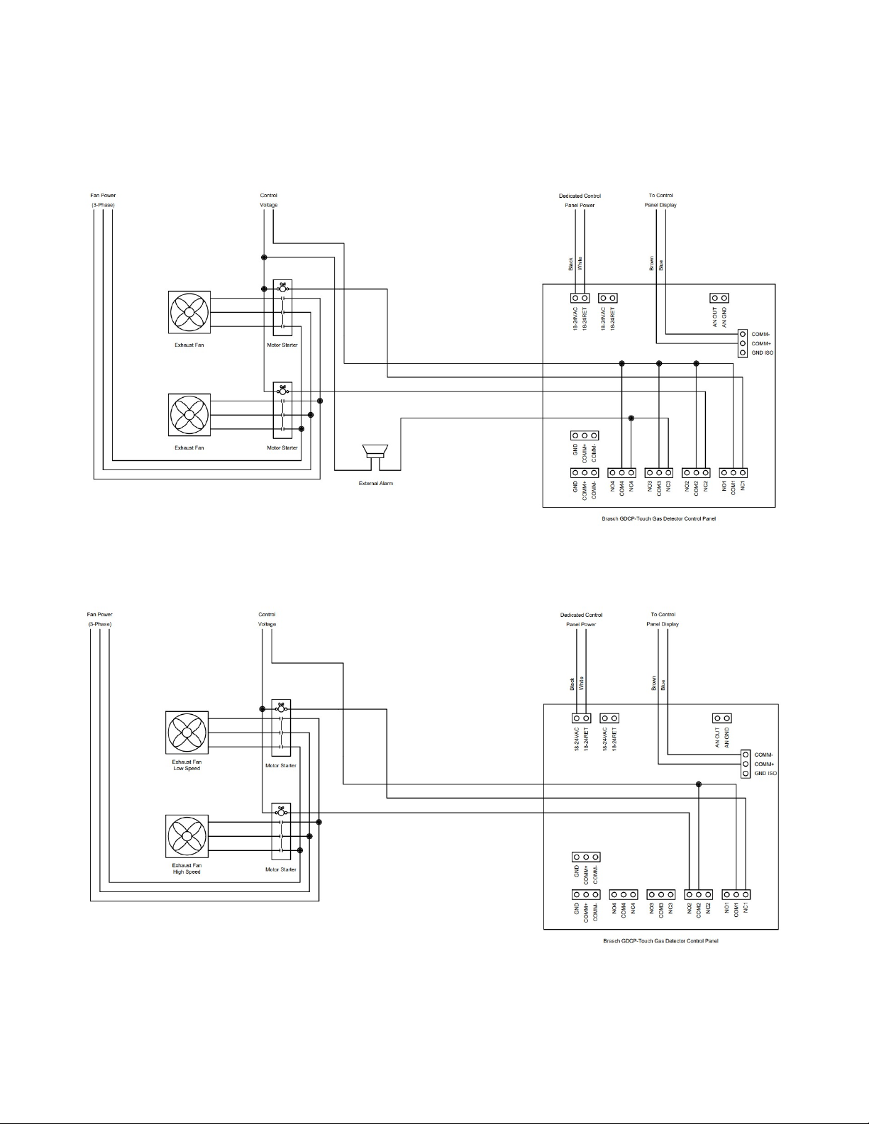
T pical Installation Diagrams
IOM03
Rev . – May 8, 202 20
Figure : Wiring – Two Fan Ventilation System with Common Alarm
Figure 2: Wiring – Two-Speed Fan Ventilation System
Table of contents
Other Brasch Control Panel manuals


