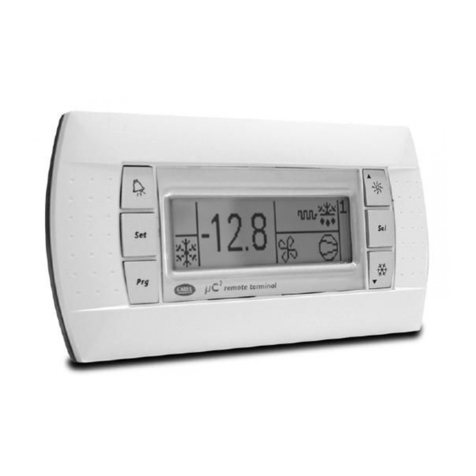
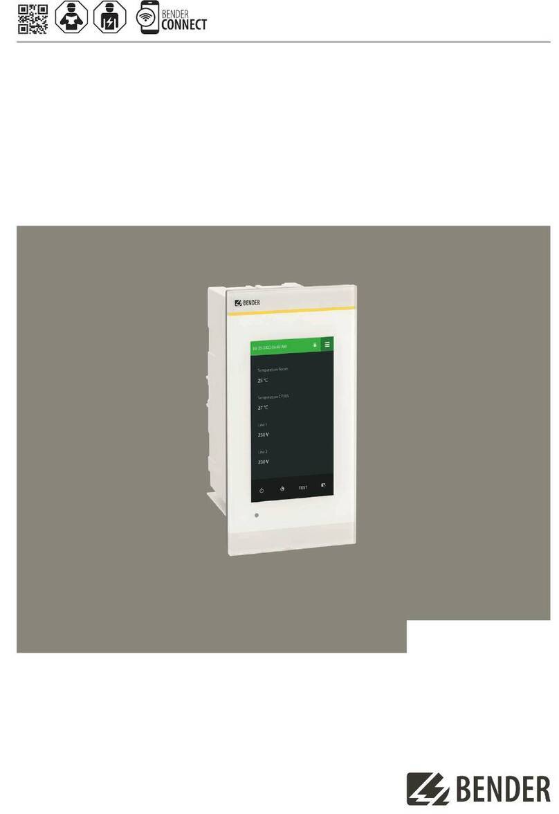
Bender COMTRAXX CP305 User manual

COMTRAXX® CP305 - Control Panel
Remote alarm indicator for medical locations and other areas
CP305_D00425_00_M_XXEN_09.2022 Manual EN

Kundenservice / First Level upport
Technische Unterstützung
Carl-Benz-Strasse 8 • 5 05 Grünberg • Germany
Telefon: +49 6401 807-760
0700BenderHelp *
Fax: +49 6401 807-629
E-Mail: suppor[email protected]
65 Tage von 07:00 - 20:00 Uhr (MEZ/UTC +1)
* Festnetz dt. Telekom: Mo-Fr von 9-18 Uhr: 6, Cent / 0 Sek.; übrige Zeit: 6, Cent / Min.
Mobilfunk: höher, abhängig vom Mobilfunktarif
Reparatur / Repair ervice
Reparatur-, Kalibrier-, und Austauschservice
Londorfer Strasse 65 • 5 05 Grünberg • Germany
Telefon: +49 6401 807-780 (technisch) oder
+49 6401 807-784, -785 (kaufmännisch)
Fax: +49 6401 807-789
E-Mail: [email protected]
Kundendienst / Field ervice
Vor-Ort-Service
Telefon: +49 6401 807-752, -762 (technisch) oder
+49 6401 807-75 (kaufmännisch)
Fax: +49 6401 807-759
E-Mail: eldser[email protected]
Mo-Do 07:00 - 16:00 Uhr, Fr 07:00 - 1 :00 Uhr (MEZ/UTC +1)
Table: ervice und upport für Bender-Produkte
2 CP 05_D00425_00_M_XXEN_09.2022

COMTRAXX® CP 05 - Control Panel
Table of contents
1 General instructions.........................................................................................6
1.1 How to use the manual..............................................................................................................................6
1.2 Indication of important instructions and information................................................................... 6
1.2.1 Signs and symbols........................................................................................................................................6
1. Training courses and seminars................................................................................................................ 7
1.4 Delivery conditions...................................................................................................................................... 7
1.5 Inspection, transport and storage..........................................................................................................7
1.6 Warranty and liability.................................................................................................................................. 7
1.7 Disposal of Bender devices.......................................................................................................................8
1.8 Safety.................................................................................................................................................................8
2 Intended use..................................................................................................... 9
3 Product description........................................................................................10
.1 Scope of delivery........................................................................................................................................10
.2 Device features............................................................................................................................................10
. System description.................................................................................................................................... 12
.4 Interfaces....................................................................................................................................................... 1
4 Mounting.........................................................................................................15
4.1 Dimension diagram CP 05.....................................................................................................................15
4.2 Flush-mounting...........................................................................................................................................15
4. Surface mounting...................................................................................................................................... 18
4.4 Retrot: Replacement of MK24 0........................................................................................................ 19
5 Connection...................................................................................................... 20
5.1 Safety instructions..................................................................................................................................... 20
5.2 Connection diagram................................................................................................................................. 22
5. Ethernet connection................................................................................................................................. 25
5.4 Digital inputs and outputs (CP 05-IO only)..................................................................................... 25
6 Commissioning............................................................................................... 27
7 oftware update.............................................................................................29
CP 05_D00425_00_M_XXEN_09.2022

Table of contents
8 Factory settings for communication.............................................................30
9 Display and operation................................................................................... 31
10 Display CP305: Menu structure.....................................................................33
10.1 Measured values.........................................................................................................................................
10.2 Bus overview................................................................................................................................................
10. History.............................................................................................................................................................
10.4 Alarm and test............................................................................................................................................. 5
10.5 Settings........................................................................................................................................................... 6
10.6 Info................................................................................................................................................................... 40
11 Web user interface: menu structure (via ETH socket)................................. 41
11.1 COMTRAXX® user interface..................................................................................................................... 42
11.1.1 Header............................................................................................................................................................ 42
11.1.2 Navigation.....................................................................................................................................................42
11.1. Subnavigation..............................................................................................................................................4
11.1.4 Content section...........................................................................................................................................4
11.1.5 Alarm overview (footer)...........................................................................................................................4
11.2 Start................................................................................................................................................................. 44
11. System overview.........................................................................................................................................44
11. .1 Device tools..................................................................................................................................................44
11. .2 Menu............................................................................................................................................................... 45
11. . BMS.................................................................................................................................................................. 46
11.4 Alarm overview (footer)...........................................................................................................................46
11.5 Tools.................................................................................................................................................................46
11.5.1 Monitoring.................................................................................................................................................... 46
11.5.2 Device management.................................................................................................................................48
11.5. Service.............................................................................................................................................................49
11.5.4 Information...................................................................................................................................................49
12 Web user interface: ettings (via ETH socket)............................................. 50
12.1 Digital inputs 1-12 (CP 05-IO only).....................................................................................................50
12.2 Relay 1-2 (CP 05-IO only)........................................................................................................................51
12. Interface......................................................................................................................................................... 51
12.4 Individual texts............................................................................................................................................52
12.5 History.............................................................................................................................................................52
4 CP 05_D00425_00_M_XXEN_09.2022

COMTRAXX® CP 05 - Control Panel
12.6 Clock................................................................................................................................................................5
12.7 Display............................................................................................................................................................ 5
12.8 Security...........................................................................................................................................................5
12.9 Buzzer..............................................................................................................................................................54
12.10 Service inspection......................................................................................................................................54
12.11 Factory setting.............................................................................................................................................55
13 Web user interface: Menu structure (access via gateway).......................... 56
1 .1 Device tools..................................................................................................................................................56
1 .2 Menu............................................................................................................................................................... 57
1 .2.1 Edit texts........................................................................................................................................................57
1 .2.2 Info................................................................................................................................................................... 57
14 Export and import of device data.................................................................58
15 Cleaning, servicing and troubleshooting.....................................................59
15.1 Cleaning......................................................................................................................................................... 59
15.2 Servicing........................................................................................................................................................ 59
15. Error messages............................................................................................................................................ 59
15.4 LED................................................................................................................................................................... 59
15.5 Malfunctions.................................................................................................................................................60
15.6 Recurring inspections...............................................................................................................................60
16 Technical data................................................................................................. 62
16.1 Tabular data..................................................................................................................................................62
16.2 Standards and approvals.........................................................................................................................68
16. Ordering information................................................................................................................................68
17 EU Declaration of Conformity....................................................................... 70
CP 05_D00425_00_M_XXEN_09.2022 5

General instructions
1 General instructions
1.1 How to use the manual
This manual is intended for qualied personnel working in electrical engineering and
electronics! Part of the device documentation in addition to this manual is the enclosed
supplement " Safety instructions for Bender products".
Read the operating manual before mounting, connecting and commissioning the
device. Keep the manual within easy reach for future reference.
1.2 Indication of important instructions and information
DANGER
Indicates a high risk of danger that will result in death or serious injury if not avoided.
WARNING
Indicates a medium risk of danger that can lead to death or serious injury if not avoided.
CAUTION
Indicates a low-level risk that can result in minor or moderate injury or damage to
property if not avoided.
Information can help to optimise the use of the product.
1.2.1 igns and symbols
Disposal Protect from moisture Protect from dust
Temperature range Recycling RoHS directives
6 CP 05_D00425_00_M_XXEN_09.2022

COMTRAXX® CP 05 - Control Panel
1.3 Training courses and seminars
Regular face-to-face or online seminars for customers and other interested parties:
www.bender.de -> Fachwissen -> Seminare.
1.4 Delivery conditions
The conditions of sale and delivery set out by Bender GmbH & Co. KG apply. These can be
obtained in printed or electronic format.
The following applies to software products:
"Softwareklausel zur Überlassung von Standard- Software als Teil von Lieferungen,
Ergänzung und Änderung der Allgemeinen Lieferbedingungen für Erzeugnisse
und Leistungen der Elektroindustrie" (software clause in respect of the licensing
of standard software as part of deliveries, modications and changes to general
delivery conditions for products and services in the electrical industry)
1.5 Inspection, transport and storage
Check the shipping and device packaging for transport damage and scope of delivery. In the
event of complaints, the company must be notied immediately, see "Technical support: Service
and support".
The following must be observed when storing the devices:
1.6 Warranty and liability
Warranty and liability claims for personal injury and property damage are excluded in the case of:
•Improper use of the device.
•Incorrect mounting, commissioning, operation and maintenance of the device.
•Failure to observe the instructions in this operating manual regarding transport,
commissioning, operation and maintenance of the device.
•Unauthorised changes to the device made by parties other than the manufacturer.
•Non-observance of technical data.
•Repairs carried out incorrectly.
•The use of accessories or spare parts that are not provided, approved or recommended
by the manufacturer.
CP 05_D00425_00_M_XXEN_09.2022 7

General instructions
•Catastrophes caused by external inuences and force majeure.
•Mounting and installation with device combinations not approved or recommended by
the manufacturer.
This operating manual and the enclosed safety instructions must be observed by all persons
working with the device. Furthermore, the rules and regulations that apply for accident
prevention at the place of use must be observed.
1.7 Disposal of Bender devices
Abide by the national regulations and laws governing the disposal of this device.
For more information on the disposal of Bender devices, refer to
www.bender.de -> Service & Support.
1.8 afety
If the device is used outside the Federal Republic of Germany, the applicable local standards and
regulations must be complied with. In Europe, the European standard EN 50110 applies.
DANGER Risk of fatal injury due to electric shock!
Touching live parts of the system carries the risk of:
•Risk of electrocution due to electric shock
•Damage to the electrical installation
•Destruction of the device
Before installing and connecting the device, make sure that the installation has been de-
energised. The rules for working on electrical systems must be observed.
8 CP 05_D00425_00_M_XXEN_09.2022

COMTRAXX® CP 05 - Control Panel
2 Intended use
Remote alarm indicator COMTRAXX® CP 05 is used for visual and audible signalling of
operating and alarm messages from the Bender systems MEDICS®, ATICS®, EDS and RCMS. In
MEDICS® monitoring systems, the CP 05 meets the requirements of standard DIN VDE 0100-710
with regard to test functions for IT system monitoring and alarms from changeover devices. IT
system monitoring equipment are tested via the test button and the devices to be tested.
Important display functions
•Normal operation indicator
•Insulation fault
•Overload
•Overtemperature
•Interruption of the system conductor or PE conductor connection of the ISOMETER®
•Supply line failure
•Power supply fault conditions and changeover device faults
•Hazard current
•Device failure
•Test results
•Measured values
The connection between the CP 50 and the transfer switching and monitoring modules is
implemented with bus technology. During normal operation, the CP 05 indicates the readiness
for operation of the system.
Version CP305-IO features 12 digital inputs, allowing messages from other technical equipment
to be recorded and displayed on the CP 05, such as from medical gases or battery-supported
safety power supply systems (BSV systems). Two relay contacts enable messages to be forwarded
to the higher-level building management system (BMS).
CP 05 devices are used in
•Healthcare facilities
•Industrial and oce buildings
•Public buildings
Please heed the limits of the area of application indicated in the technical specications.
Operator control and adjustment of settings is partly done directly on the device or in a web
browser.
Any other use than that described in this manual is regarded as improper.
Intended use includes:
•Equipment-specic settings compliant with local equipment and operating conditions
•Observation of all information in the operating manual
•Compliance with test intervals
CP 05_D00425_00_M_XXEN_09.2022 9

Product description
3 Product description
3.1 cope of delivery
You get
•Remote alarm indicator CP 05…
•Connection plug kit CP 05 (power supply, RS485 connection)
•Additionally for CP 05-IO: connections for the digital inputs and relay contacts
•A printed quick reference guide (the manuals are available at:
www.bender.de > Service & Support > Download area > Operating manual)
•Safety instructions for Bender products
Versions
•CP 05 (remote alarm indicator)
•CP 05-IO (remote alarm indicator with 12 digital inputs and 2 relays)
Installation options
•Flush-mounting (ush-mounting enclosure B92 710)
•Surface mounting (surface-mounting enclosure B9510015 )
•Cavity wall mounting (cavity wall mounting set B92 711)
•Retrot (CP 05 can be inserted directly into existing MK24 0 ush-mounting enclosure;
other devices on request)
3.2 Device features
Characteristics
On its display, the CP 05 shows the messages of all BMS bus participants that have been
assigned to it via alarm addresses. As well as being used as a standalone indicator, a CP 05 also
supports parallel indication of several CP 05 in dierent rooms.
Parameters can be set for the alarm colours for the LED (e.g. red for an alarm, yellow for a warning
such as an insulation fault or the like).
In case of a message, there is an alarm pop-up (display). This is in addition to the LED as well as
an entry in the alarm overview (web user interface). An audible signal for which parameters can
be set also sounds (can be acknowledged/can be muted).
If a second message is received while the rst is still pending, the audible signal will sound again
and the messages appear alternately on the display. The address of the device triggering the
alarm can also be displayed. The audible signal sounds again once a congurable period of time
has elapsed (repetition can be deactivated).
10 CP 05_D00425_00_M_XXEN_09.2022

COMTRAXX® CP 05 - Control Panel
Internal device parameters (alarm addresses, test addresses…). Parameters can be set for
individual message texts for each alarm and test address. The CP 05 can be used as a master
device in installations with several IT and EDS systems.
The “TEST” button can be used to check the function of the associated devices such as insulation
monitoring devices, LIM (Line Isolation Monitors) and GFCI (Ground Fault Circuit Interrupters).
A message is only sent to the CP 05 on which the test was started. The test and its individual
evaluations are carried out sequentially. Finally, a message appears that the test was successful or
an error message will be output.
The CP 05 has the following features
•Display of operating status, warning and alarm messages according to DIN VDE 0100-710,
IEC 60 64-7-710 and other standards
•Plain text display with illuminated 5" touch display
•Easy to clean and disinfect, degree of protection IP54 (entire device) or IP66 (front glass
pane)
•Front panel mounted without screws
•User-friendly, touch-sensitive monitoring system for medical areas and other applications
•Particularly simple operator guidance
•Additional information for medical and technical personnel
•Visual and audible notication in the event of an alarm
•Clear menu structure
•Silent due to fan-free operation
•High-quality display with excellent contrast, high resolution and a wide-viewing angle
•Device tests and parameter setting changes with minimal service interruptions
•Standard texts for messages in the national language
•500 freely programmable alarm messages
•Bus technology for easy installation and reduced re load
•Audible alarm (can be acknowledged or muted)
•Version for ush mounting and surface mounting
•Easy putting into service due to predened alarm text messages
•History memory with real-time clock to store 1000 warnings and alarms
•Power supply via power supply unit
•Parameter setting via Ethernet interface
•NFC interface for connection to the Bender Connect app
•Replacing MK24 0 (retrot); other devices on request
Additionally CP 05-IO
•12 digital inputs
•2 relay contacts (changeover contact)
CP 05_D00425_00_M_XXEN_09.2022 11

Product description
Applications
•Visualisation on the display optimally tailored to the user
•Integration of all compatible Bender products (MEDICS®, ATICS®, EDS, Linetraxx® RCMS
systems and ISOMETER®)
•Individual instructions for action in the event of alarms
3.3 ystem description
Certication
COMTRAXX® CP 05 are UL certied.
MEDIC ®
The CP 05 remote alarm indicators are components of the MEDICS® systems. MEDICS® is an
intelligent system that guarantees safe power supply in medical locations.
Connection example BM
tation Base
BMS intern (RS-485)
CP305
CP305
ATIC ® ATIC ®
ED 151 ED 151
CP9xx
In the example, the ICU is monitored from the station base via BMS bus.
12 CP 05_D00425_00_M_XXEN_09.2022

COMTRAXX® CP 05 - Control Panel
Connection example BM and Ethernet
In the example, the ICU can be monitored from the station base. In addition, remote
maintenance is possible via the building services or Bender.
3.4 Interfaces
BM
The BMS bus is used for communication with BMS bus nodes or devices like RCMS…, EDS…,
SMI…, SMO…, ATICS®, alarm indicator and operator panels. The CP 05 acts as the master
whenever the address is set to 1 and as CP 05 slave when the address is set between 2 and 90.
The master controls the data trac on the BMS bus.
Remote alarm indicator CP30 is to be operated as a master if
- Parameters are queried or changed.
- Certain control commands were given.
Addressing
For remote alarm indicator CP 05 to function properly, it must be correctly addressed.
Terminating resistor
For correct functioning of the CP 05 remote alarm indicator, its correct termination is of
fundamental importance. The rst and last device on the BMS bus must be terminated with a
terminating resistor (daisy chain). If the CP 05 is to be terminated, the terminating resistor is
switched on with a dip switch on the bottom of the device.
CP 05_D00425_00_M_XXEN_09.2022 1

Product description
On O
Dip switch on the bottom of the CP 05
Ethernet
Using the RJ45 interface “ETH”, the CP 05 can be addressed via Ethernet. The web server required
for this is included in the device. The congured IP address can be found on the device under
> Info.
The web user interface can be used to adjust all device settings.
NFC (near-eld communication)
The powered device can also have its parameters set via NFC. The interface is activated on the
CP 05 under > Settings > Interface > NFC. Afterwards, the prepared conguration can be
loaded onto the device using the Bender Connect app.
14 CP 05_D00425_00_M_XXEN_09.2022

COMTRAXX® CP 05 - Control Panel
4 Mounting
4.1 Dimension diagram CP305
All dimensions are in mm.
96 8,1
181
7,1
4.2 Flush-mounting
The ush-mounting enclosure is optionally available (B923710).
CP 05_D00425_00_M_XXEN_09.2022 15

Mounting
Dimension diagram ush-mounting enclosure
All dimensions are in mm.
75
55
2.7
160
165
80
16 CP 05_D00425_00_M_XXEN_09.2022

COMTRAXX® CP 05 - Control Panel
Installation of ush-mounting enclosure
1. Insert the supplied cardboard into the ush-mounting enclosure to provide protection
against pollution.
2. Insert the enclosure so that it is ush with the wall surface.
The ush-mounting enclosure must not be installed lopsidedly or warped, and must not be
installed too deep below the surface.
CP 05_D00425_00_M_XXEN_09.2022 17

Mounting
4.3 urface mounting
For surface mounting, the matching surface-mounting enclosure (item no. B9510015 ) must be
used.
All dimensions are in mm.
59
185.5
100.5
18 CP 05_D00425_00_M_XXEN_09.2022

COMTRAXX® CP 05 - Control Panel
Cavity wall and panel mounting
For cavity wall or panel mounting, you need the “Cavity wall mounting set” (item no. B92 711).
Cavity wall
mounting
Panel mounting
4.4 Retrot: Replacement of MK2430
In the context of retrot measures, CP 05 can be installed directly in the existing ush-mounting
MK24 0 enclosures.
If MK2418, MK2410 or other devices are to be replaced, the ush-mounting enclosures must
be changed. Please contact Bender Service for details.
CP 05_D00425_00_M_XXEN_09.2022 19

Connection
5 Connection
5.1 afety instructions
Only skilled persons are permitted to carry out the work necessary to install, put into service
and run a device or system.
DANGER Danger of electric shock!
Follow the basic safety rules when working with electricity. Observe the information on
rated voltage and supply voltage specied in the technical data!
DANGER
Connect the CP 05 exclusively according to the connection diagram in this chapter. Do
not make any changes to the internal wiring. Non-compliant connection or arbitrary
changes can lead to serious malfunctions or even complete failure of the CP 05.
CAUTION
Electrostatic discharge sensitive devices
Observe the precautions for handling electrostatically sensitive devices.
Damage to components
Do not remove the device from the enclosure while it is in operation. Disconnect the
device from the power supply and the network (Ethernet) beforehand.
Damage to the device due to incorrect connection plug
Connectors of other devices may have polarity that diers. You are required to use the
enclosed connector plug (A1/+, A2/-).
afe separation
The power supply must be properly insulated from hazardous voltages and meet the
limits of UL/CSA 6101010-1 (6. ).
To comply with the requirements of DIN VDE 0100-710, AC power supplies with max. 2 VAC
must be used.
All enclosed connectors should always be plugged in even when they are not in use.
20 CP 05_D00425_00_M_XXEN_09.2022
Other manuals for COMTRAXX CP305
3
Table of contents
Other Bender Control Panel manuals
Bender
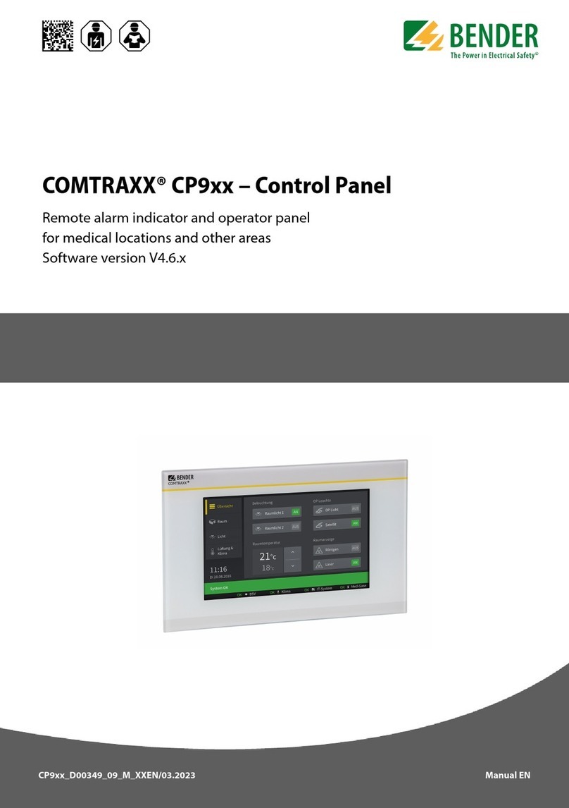
Bender COMTRAXX CP9 Series User manual
Bender
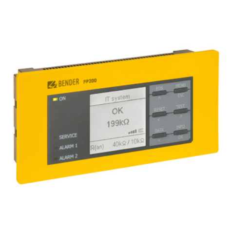
Bender FP200 User manual
Bender
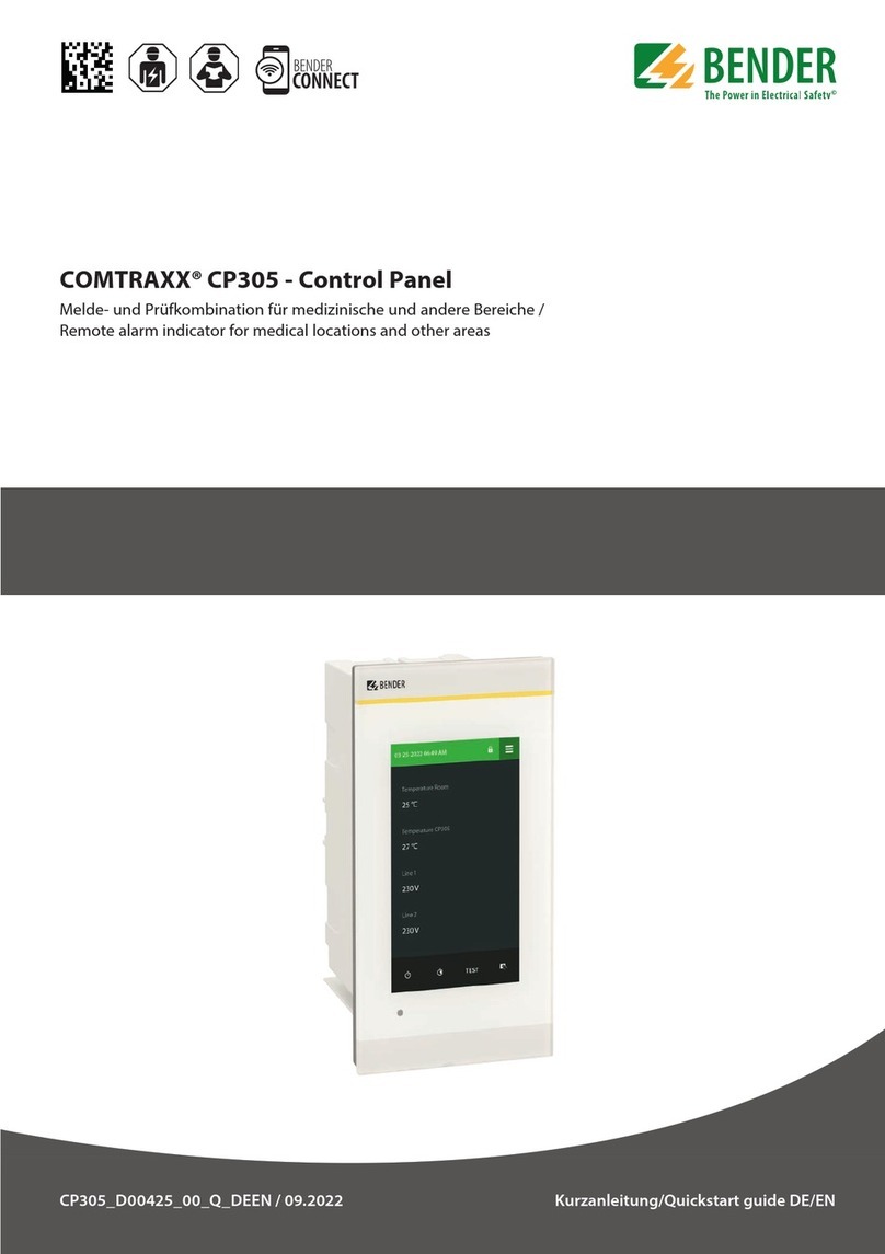
Bender COMTRAXX CP305 User manual

Bender
Bender COMTRAXX CP9 Series User manual
Bender
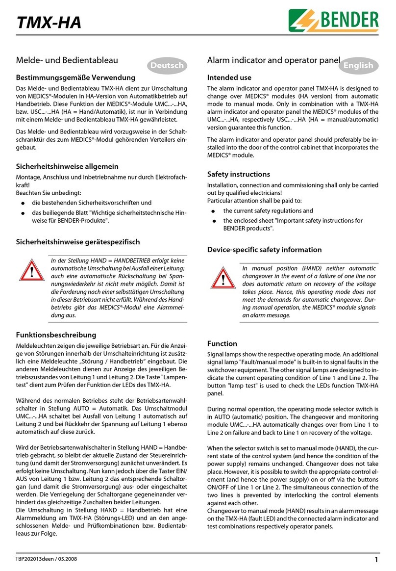
Bender TMX-HA User manual
Bender
Bender COMTRAXX CP305 User manual

Bender
Bender COMTRAXX CP9 Series User manual

Bender
Bender COMTRAXX CP9 Series User manual
Bender
Bender PRC487 User manual

Bender
Bender COMTRAXX CP9 Series User manual
