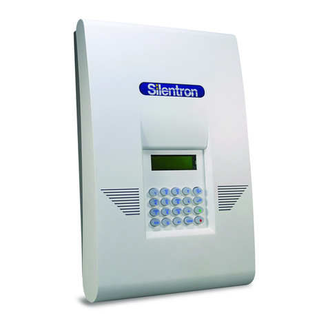
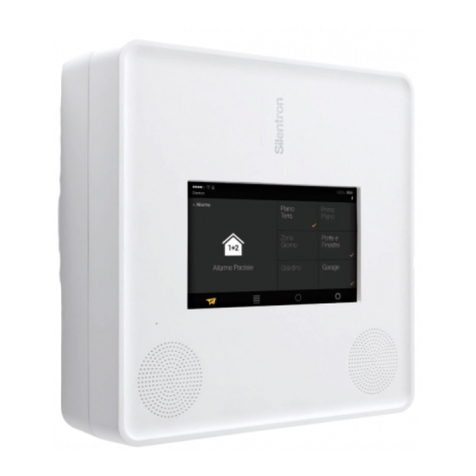
SILENTRON SERENYA MIX GSM 2001 User manual

COPYRIGHT SERENYA COD. 2001
SERENYA by Silentron –made in Italy
SERENYA MIX GSM (cod. 2001)
Mixed wired/wireless control panel with GSM telephone transmitter

COPYRIGHT SERENYA COD. 2001
SERENYA by Silentron –made in Italy
DECLARATION OF CONFORMITY :
Date: 1st January 2010 Producer name: Silentron S.p.A. Addresse: Via Sagra S. Michele 25/27 - 10139 TORINO - ITALIA
The producer declares under his own responsibility that this product is in compliance with that envisioned by the following European Community
Directives::
- Directive of the European Parliament 1999/5/CE (R&TTE) of March the 9th, 1999 concerning the radio and the terminal telecommunication
equipments and the reciprocal recognition of their compliance.
-Directive of the European Parliament 2004/108/CE of December the 15th, 2004, for the approximation of the laws of the Member States
relative to electro-magnetic compatibility.
- Directive of the European Parliament 2006/95/CE of December the 12th, 2006, for the approximation of the laws of the Member States relative
to electric material destined to be used within certain voltage limits.
GENERAL NOTICES AND WARNIGS
Read carefully before using the appliances
Installation: all installation, maintenance and/or modification of these control units and their devices must be carried out by qualified technical
staff. These operations can be subject to specific technical Standards which must be complied with. The device is envisioned to be used
exclusively inside buildings protected from exposure to very high and very low temperatures as well as tampering by children and/or persons
without common sense for the purpose and effects of the Civil Code.
Electrical connections:every electrical connection without exceptions must be made perfectly fixing all the wires as foreseen in order to avoid
accidental detachment and closing correctly boxes and protections of the devices. It's made obligation to disconnect all the electrical
connections having more then 25V in DC and AC before opening boxes of actives devices.
External power supply: Normalized feeder with plug model ADPV61K INPUT: AV. J. - C. -100-240V 50/60Hz 15VA OUTPUT: DC 14,2V
0,75A. The device must be only connected to the supplied feeder: different power sources can irreparably damage the device and can be
source of fire danger.
Batteries: this device uses batteries, that are potentially dangerous as they are pollutant, therefore dangerous to the health of the public.
Replace the batteries exclusively with same models, position and connect them respecting the polarity indicated in the instructions. It is
mandatory to dispose of accumulators/waste batteries according to the Standards in force. This is also the case when the devices must be
scrapped. The batteries must be previously removed, returning them to the seller or depositing them in the relevant containers made available
by the distribution network. If liquid should escape from the batteries, use silicone gloves to protect the hands and prevent injury.
Liability: the manufacturer declines all liability consequent to incorrect installation, maintenance and/or failure to use the devices supplied.
Failure to comply with standards for installation and failure of compliance with the requirements of this manual.
CE Warranty: 2 years from the purchasing, based on the date reported in the corresponding invoice..
Copyright : all rights relative to this manual are the property of Silentron S.p.a.. It is prohibited to partially or totally reproduce the texts and
imaged herein, as is the introduction into W.E.B. network and/or public distribution with any means.
INDEX
1) FIRST PART - CONFIGURATION OF SERENYA WIRELESS SYSTEM
SERENYA control panels: available models
Other devices components of an alarm system
Glossary of specific terms
2) SECOND PART –GENERAL FEAUTURES AND FUNCTIONS
Intrusion alarm partitions –Technical alarm partitions –Arming/Disarming - signals and alarms –Telephone Calls - Vocal/sms
messages - home functions -functioning of outdoor sirens
3) THIRD PART –CONTROL PANEL FUNCTIONING
Installer Code - USER –user’s operations: arming/disarming
Control Panel Test –battery replacement
Reading the events memory –Operation at fixed time –Remote operations: guide message
Calls to the control panel: queries and remote operations - Using the GSM telephone - Residual credit - Remote listening - Other GSM
functions
4) FOURTH PART –CONTROL PANEL PROGRAMMING
Introduction of the programming code - Main menu –Telephone book programming
Telephone book modification –Vocal messages recording –SMS writing
Vocal messages programming - sms –Key-fobs programming
Extras Menù: Programming of codes for arming/disarming
Extras Menù: Programming of Intrusion and 24h alarm partitions
Settings Menù: detectors exclusion –radio commands
Settings Menù: Mains failure - Periodic message –SIM Expiry - Time/date –Installer code –antiscanner –supervision
Settings Menù: Exit time –summer time –backlighting –volume –Forced arming
Firmware version –Total reset
Settings Menù: Programming alarms/keypads
5) FIFTH PART –CONTROL PANEL INSTALLATION
6) SIXTH PART –TECHNICAL FEAUTURES
Technical feautures
Illustrations
FOR A PROPER UNDERSTANDING OF THE PRODUCT WE SUGGEST TO COMPLETELY READ THIS MANUAL

COPYRIGHT SERENYA COD. 2001
SERENYA by Silentron –made in Italy
1) FIRST PART - CONFIGURATION OF SERENYA WIRELESS SYSTEM
The Serenya control panels makes up represent the brain of a security alarm system with home automation options made possible by the
integration of the control unit with various types of detectors or sensors, control means and dissuasion and alarm devices. The dimensional limit
is given mainly by the radio range of the devices, which can be amplified through appropriate repeaters.
The Serenya control panels can also manage relevant outdoor detectors , informing the user indoor and giving place to dissuasion signals for
the intruder but not disturbing other peoples. This because the outdoor detectors may generate improper alarms due to unavoidable natural
phenomena which interact with the equipment and do not depend on defects of the devices.
Before operating on the devices the installation project of the system to be realised must be clear because programming the control unit and
the satellites depends on the result that is to be obtained by the technical/operational choices made..
1.1) SERENYA : AVAILABLE MODELS AND THEIR APPLICATIONS
All SERENYA control panels are "speaking" since they permit to record vocal messages to inform the user, in addition to the usual vocal
messages transmitted via telephone; these last they don’t inform the user vocally only for intrusions and troubles, but they specify the device
which generated it, simplyfing a lot interventions.
Code 2000 SERENYA GSM WIRELESS: control panel supplied exclusively with battery for completely wireless installations, independent
from the electric network, with a very good security level and a good home automation flexibility. It has an integrated GSM telephone transmitter
(it requires a SIM card), that, for obvious reasons of consumption, is switched-on temporarily in case of events to communicate: for this reason
it isn't possible to command the control panel via telephone.
Code 2001 SERENYA MIX GSM > (this manual): control panel supplied trought the 230V CA network using an external feeder (it needs a
rechargeable 12V 2,2Ah backup battery, not included), with the possibility to command sirens both wired and wireless. It provides a very good
security level and a good home automation flexibility thanks to the always active integrated GSM telephone transmitter (it requires a SIM card),
allowing to command the control panel via telephone and to receive events communications.
Code 2002 SERENYA PSTN MIX: control panel similar to the model 2001, but without GSM module therefore the transmission aspects of the
alarms and reception of the radio commands they depend only by the fix telephone line (PSTN), through of which it's possible to manage the
control panel.
Code 2003 SERENYA PSTN WIRELESS: control panel similar to the model 2000, but without GSM module therefore the transmission aspects
of the alarms and reception of the radio commands they depend only by the fix telephone line (PSTN), through of which it's possible to manage
the control panel.
Code 2004 SERENYA PSTN+GSM MIX: control panel supplied trought the 230V CA network using an external feeder (it needs a rechargeable
12V 2,2Ah backup battery, not included), with the possibility to command sirens both wired and wireless. It has an integrated double telephone
transmitter, one for fix line (PSTN), one GSM (it requires a SIM card) for the events transmission and commands reception via one of the two
communication systems.
1.2) ARMING/DISARMING DEVICES –it’s possible to program up to 10 key-fobs and an unlimited number of keypads (look Warning )
SERENYA control panels can be commanded trought the on-board keypad, or trought bidirectional key-fobs (Code 2023) and/or trought
bidirectional keypads (Code 2028) qui confirment les opérations effectuées:. Soit les télécommandes que les claviers disposent de touches
fonction pour activer alarmes PANIQUE et AGGRESSION.
1.3) ALARM DEVICES –it’s possible to program an unlimited number of alarm devices (look Warning)
The telephone alarm transmission as well as the siren integrated in the control cannot be considered sufficiently dissuasive at the local level.
We suggest to complete the system using optical and acustical alarm devices to create bewilderment in the intruder as the external wireless
siren Code 2032 (alarm type: voice, flash and sound) or the wired external siren Code 2039 (alarm type: flash and sound), as well as the
internal sirens Code 2034 and 2035.
1.4) DETECTORS –It’s possible to program up to 50 detectors (look Warning)
A complete range of wireless detectors is available: Code 2018 and 2021 for the internal volumetric protection, Code 2016 for doors/windows
protection, Code 2020 for rolling shutters protection and Code 2014 for the protection of the external areas of the building. The choice of the
correct detectors it's a compromise bound to the local structures and the objectives we want to get by the electronic protection. Attention: more
a detector is "sensitive", more are the possibilities to have improper alarms.
SERENYA control panels can also manage fire, flooding, gas flight (available on demand) and other detectors, therefore they permit a complete
protection against dangers.
1.5) ACCESSOIRES –on peut programmer illimités interrupteur sans fils, sur 16 commandements différents
Operating in wireless conditions it is simple to complete an alarm installation with useful home automations, which can be controlled on
site or at a distance via telephone. Switching on lights on passage, controlling shutters, blinds, motorised gates, inserting central hating and air
conditioning are only a few of the operations that the SERENYA control panels make possible trought small wireless switches Code 2041 and
2042.
1.6) BATTERIES –LIFE TIME
Batteries used in the SERENYA system are cheap and simple to find on the market, for the USER's biggest serenity. The declared life time of
the different devices are unfortunately variable depending by their use and by their number in the context of the system: solicitations repeated
and continuous of detectors gives as result more consumption; a greater number of system components and a lot of Arming/Disarming per day
they increase the consumption of the control panels and sirens supplied by battery: these phenomena obliges a more frequent replacement of
the batteries. The rechargeable batteries also consume their power, and they must be replaced at least every 4 years.
Warning: bidirectional keypads and sirens can transmit their own Tamper alarm to the control panel. In order to allow their Tamper
control they’ve to be programmed also as a detector (look at the specific instructions), so each one takes one of the 50 available
locations for detectors, reducing their possible number. Every manual command PANIC and HOLD-UP programmed trought the key-
fobs takes a location too. It’s important to consider these aspects realizing the system.
1.7) GLOSSARY
ALARM (various types) There are various types of alarm, which give different consequences. The "intruder" alarm dissuades and warns
from outdoors. The “panic” alarm supposes that the user wants to draw attention by activating the sirens, while the

COPYRIGHT SERENYA COD. 2001
SERENYA by Silentron –made in Italy
“hold-up” alarm supposes a direct robbery, where it is better just to activate telephone calls only. The technical
alarm must warn without causing fear.
FALSE ALARM: Alarm caused by a defect and/or failure of one or more devices (covered by industrial warranty)
IMPROPER ALARM: Alarm caused by incorrect positioning, technical limit of device and/or random accidental causes independent of
the equipment itself (not covered by industrial warranty).
ALARM partition Group of detectors, can be armed/disarmed individually or with other groups (partitions A-B-C). The 24-hour
partitions panic-holdup-technological are always armed. The detectors must be appropriately divided among the
various partitions to allow flexibility of use.
ALARM channel Single location of a specific detector (two in the case of AND) which protects an area, a point, a surface, a
passage. Sometimes the term "zone" is improperly used to indicate a "channel".
AND Control unit function useful to greatly reduce the probability of improper alarms: two detectors are installed to
protect the same area and/or passage, programming them in AND on the same channel. The alarm will only occur
with the detection of both devices within the pre-established 30 seconds time. If the detectors are the same type
they must be installed opposite; if different type (different technologies) according to logic.
.
ANTI-COERCION Control panel’s function that allows to disarm the system composing a different code by the usual one, and at the
same time activate silently the emergency telephone calls.
DETECTOR EXCLUSION Operation which allows to inhibit a detector temporarily (due to failure or other reason) until reset.
HOME AUTOMATION Electronic/electro-mechanical automation system for activities in the home (lights and household appliances).
TAMPERING Attempt to open the cases of the appliances of the devices and/or remove them and/or other, with the purpose of
preventing functioning.
EVENTS MEMORY: Various forms of indelible recording of occurred events, which can have legal value.
PRE-ALARM: Control panel state prior to actual alarm, caused by detectors programmed with alarm delay or state of the outside
sirens before sounding
RADIO RANGE : max distance between a transmitter (detectors, key-fobs, keypadss) and a receiver (control panel, sirens). In our
case, because of the low transmission power imposed by the Rules, the radio range can change a lot,
especially inside environments where the position of the transmitter in relation to the receiver is basical. Besides
walls and furniture sometimes create reflections of the radio signals (increasing or reducing the range).
consequently it is necessary to always verify the radio range (readable on the control panel) and to improve it in
the extreme cases: small position changement (more or less 10 centimeters) often allow important
improvements.
ALARM delay: Time between the detector transmission and the actual alarm: it is adjustable on the Silenya HT control panels
Individually for each detector.
DETECTOR: Equipment designed to signal an intrusion, passing, open door/window and any other event which poses a danger.
Equivalent term used in the manual: SENSOR
TEST: Control unit test condition which blocks all sirens and also allows checks and battery replacements.
SECOND PART –CONTROL PANEL SERENYA MIX GSM –GENERAL FEAUTURES AND FUNCTIONS
This manual describes the control panel’s feautures and consequently those of the installation: many of these are consequences of the
programming performed during installation. It is the responsibility of the designer and whoever organises the system to agree the functional
aspects with the user, in order to allow effective use, suitable and non-invasive of the peace.
2.1) MAINS OPERATING FEAUTURES
2.1.1) Detectors control: it’s possible to program up to 50 wireless detectors of any type (up to 100 if programmed in AND).
2.1.2)Three intrusion alarm partitions A-B-C, with different programmable functioning philosophy:
A) Programming with outdoor detectors and consequently Outdoor Alarm Function:
- Zone A is recommended for outdoor intruder detectors: the sirens warn with acoustic signals without ringing at maximum power.
-zone B is recommended for detectors on accesses and zone C for indoor volumetric detectors: both cause GENERAL ALARMS
In this way the user can arm zones A+B when in these places: approach detected by the external sensors is signalled at low volume or with a
vocal message; whenever a protected access is successively forced, the siren is triggered at maximum power.
In the case of improper alarm of the outdoor detectors, the acoustic signals will not be such to disturb, but will remove the “surprise effect” of
intrusion.

COPYRIGHT SERENYA COD. 2001
SERENYA by Silentron –made in Italy
B) Traditional programming with all indoor detectors:
In this case all of the detector alarms cause GENERAL ALARM conditions. The intruder detectors can be divided into the three zones A, B, C
depending on the necessity for differentiated arming, considering that the remote controls have the white key that allows to arm zones A+B
automatically and the red key for full arming.
2.1.3) Accessory alarm zones, always active (24/24hrs):
- “Panic” partition to activate outdoor sirens and telephone calls via a remote control or keypad key in case of need.
- “Robbery (Hold-up)” partition to exclusively activate telephone calls via a remote control or keypad key in case of need (medical warning also)
- “Technical” partition to control smoke and water detectors or detectors of any other dangerous event, and set a specific and distinguishable
alarm.
2.1.4) Control panel Arming/Disarming:
- up to 10 bidirectional key-fobs with 4 buttonss for total arming (A+B+C), partial (A+B) and disarming with LED for visual confirmation.
- up to 10 codes of 5 digits for total/partial arming and disarming, to be used on the control panel and keypads, with ANTI-COERCION function.
- FORCED ARMING: IT’S POSSIBLE TO ARM THE CONTROL PANEL EVERY DAY AT A SPECIFIC PROGRAMMED TIME.
2.1.5) Control unit acoustic signals and alarms (see also "Telephone part")
SERENYA control panels are « speaking », so they give vocal informations recorded in English language
Pre-alarm: pre-alarm vocal messages or series of "Beeps". Sirenya sirens signals > signal by intermittent acoustic sounds
Outdoor alarm: external alarm vocal message or series of "Beeps" . Sirenya siren works in “outdoor alarm" mode.
General alarm: activation of control panel siren and of all sirens (see instructions of the sirens used) provided in the system
Panic alarm with system partially armed or disarmed: no control unit alarm, but activation of all wireless sirens provided
Robbery alarm: no control unit alarm, no sirens, but just activation of the “robbery” telephone calls. This control can also be used to
call for a doctor or request other assistance by telephone.
Technological alarm: intermittent acoustic signal from the control unit for 15 seconds.
Tampering alarm with system partially armed or disarmed: intermittent acoustic signal from the control unit for 3 minutes.
Tampering alarm with system armed: like general alarm.
Attention! Consider the following aspects:
a) In any case disarming the system will silence the sirens and phone calls. Attention: this control panel has a GSM module that during the
telephone transmission can disturb the attempts of disarming the control panel via key-fob or keypad . In this case disarm the system using the
control panel integrated keypad.
b) During each arming period of partitions A, B, C only three alarms are accepted by each detector (except 24h partition PANIC and HOLD-UP)
in order to avoid that a defective detector becomes a public disturbance. The count re-starts at every arming.
.
2.2) Bidirectional telephone part - Telephone calls
In the installation phase the relevant messages must be recorded/written and connected to telephone numbers to call in the event of alarms: for
example the ALARM will be connected to user, family or friend's numbers, numbers of intervention forces. It is useless to connect the installer's
number to the alarm calls, while it is useful to connect it to the "low battery" calls. Attention: the telephone calls to the Police Force require
previous approval, ruled differently from place to place.
This control panel works on the GSM network (mandatory use SIM card). The control panel can transmit up to 6 vocal messages, bound to the
events described here following, calling up to 20 USERS whose the number has been correctly programmed. Before the vocal messages the
correspondent SMS will be sent via the GSM network. Besides there are other already programmed SMS having technical content, that are
transmitted when the event happens. Each of the 20 available phone numbers can be enabled to receive one or more vocal messages and/or
SMS, according to the specific necessities.
2.2.1) VOCAL/SMS MESSAGES TO RECORD/WRITE:
1 - ALARM ZONES A,B,C: intrusion alarm message generated by detectors programmed on any zone A,B,C. It is possible to select the zones
so as not to transmit the message, for example, outdoor alarm coming from zone A, while the alarms from zones B
and C will be transmitted.
To these messages, either vocal that SMS, is added the position of every detector, if correctly recorded and written
during programming.
2 - TAMPERING : message always active, generated by tampering with one or more system devices. To these messages, either vocal
that SMS, is added the position of every detector, if correctly recorded and written during programming.
3 -24H PANIC : alarm message always active, generated by a manual command, for example yellow key on the remote control.
4 - 24H HOLD-UP
:
alarm message always active, generated by a manual command, for example yellow key on the remote control.
5 - 24H TECHNOLOGICAL: alarm message always active, generated by a technical alarms detector (smoke, water, gas etc.)
6 –
LOW BATTERY
:
alarm message always active, generated by a system component with low battery.
2.2.2) SMS PROGRAMMED IN THE FACTORY
1 = control unit battery flat: attention! The system will soon stop functioning!
2 = peripheral battery flat: attention! One or more detectors will cease to function shortly (days)!
3 = no supervision and/or presence of radio interference: check the events memory on return
4 = system armed: the message will be only send after an Arming operation realized by remote using a telephone
5 = system disarmed: the message will be only send after a Disarming operation realized by remote using a telephone
6 = 230V power failure and restore –the message will be send in case of power failure after the programmed time (SETTINGS)
7 = no GSM field for more than 15 min.: the message will be send on return of the GSM field
8 = not available in this model
9 = periodic message of operating status of the control unit: cyclic message every so many hours/days (SETTINGS)
0 = SIM expiry warning message: program (SETTINGS) new expiry in case of pre-paid SIM

COPYRIGHT SERENYA COD. 2001
SERENYA by Silentron –made in Italy
Identification: the correct vocal recording and writing of the "labels" of the various detectors in the programming phase allows the user to
receive all messages with the exact indication regarding the device of interest.
2.2.3) HOME AUTOMATION FUNCTIONS
A) Programmable clock: the control unit has a programmable clock for forced arming (voir 3.2.6)
B) Radio Outputs: 16 radio commands are available to command local radio switches, to be activated via telephone calling the control panel to
switch-on lights or other electrical charges. These receivers can also be activated via key-fobs, keypads, detectors (look 3.3 and followings)
2.3) FUNCTIONING OF THE SIRENS - ALSO SEE SPECIFIC MANUAL
The control panels control the indoor and outdoor radio sirens:
a) Indoor sirens: they emit an arming (partial/full 3 Beeps) and disarming (just one Beep) acoustic signal, the intensity of which can be
regulated to zero. The signal is set off for 3 minutes in the case of a general, tamper or panic alarm.
b) Outdoor sirens: they emit an arming (partial/full 3 Beeps) and disarming (just one Beep) acoustic signal, the intensity of which can be
regulated to zero and they flash at the same time. The sirens activate for 3 minutes in the case of a general, tampering or panic alarm after a
pre-alarm period of about 10 seconds, during which an intermittent acoustic signal is emitted. This delay, which cannot be changed, is intended
to prevent disturbance if one forgets to disarm the system. In the case of EXTERNAL ALARM programming the outdoor sirens are not triggered,
but the pre-alarm condition continues for up to 3 minutes or a recorder dissuasive message is played (code 2032).
3) THIRD PART –CONTROL PANEL FUNCTIONING
3.1) SECURITY PROTECTION –USER CODE –INSTALLER CODE
The control unit is provided with a factory code “0 0 0 0” which allows access to the programming procedure. During installation it is necessary
to change this code, programming other two ones (differents between them): USER code and INSTALLER code.
In case of lost or forgotten codes the only solution consists in open the control panel generating a Tamper alarm, disconnect and connect again
power supply and begin entering the factory code: this operation doesn’t delete the realized programming.
a) INSTALLER CODE: from 4 to 8 digits, which allows access to all programming but not operations.
b) USER CODE: from 4 to 8 digits, it allows the followings functions
placing the control unit in TEST mode for testing or battery change.
reading the EVENTS MEMORY
programming/modification of listed telephone numbers (see third part)
recording/modification of all vocal messages (see third part)
addition/deletion of remote controls and/or numeric arming/disarming codes (see third part)
modification of supplementary wired key function (see third part)
modification of certain SETTINGS: Exclusion of radio or wired detectors (sensors) –Clock/date setting –Change of user code –Change of
daylight-saving time –Change of display back-lighting –Regulation of vocal message volume - Change of automatic forced arming –Control
unit firmware version check
Attention! Careless with the USER code can limit the efficiency of the entire system, therefore, it is advisable to be informed on the various
functions before making any changes.
3.2) USER’s OPERATIONS – NORMAL SITUATION OF THE CONTROL PANEL
13 / 02 / 09 17,00
DISARMED _ ▄ █ █
DATE TIME
STATUS GSM SIGNAL
Date and time must be correctly programmed and upgraded at least every 6 months
(maintenance): look at the SETTINGS menù
3.2.1) ARMING - DISARMING USING THE CONTROL UNIT KEYPAD (VISUAL, VOCAL CONFIRM)
3.2.2) OPERATIONS WITH REMOTE CONTROLS AND/OR ADDITIONAL KEYPADS
TOTAL ARMING
Supplementary keypads: enter the numerical code and then press the red key
KEY-FOBS: press the red key
PARTIAL ARMING (vocal confirm or a long Beep)
Supplementary keypads: enter the numerical code, by pressing A, B, C exclude the zones that are not to be armed and then press the red key
KEY-FOBS: press the white key to arm zones A+B (for other solutions see the remote control instructions)
DISARMING
13 / 02 / 09 17,00
DISARMED _ ▄ █
Arming :enter the 5 digits code and
press the button
ARM GROUPS :
A B C
Select partitions to don’t arm using
the buttons 1,2,3 and press the button
13 / 02 / 09 17,00
ARMED A B C _ ▄ █
Disarming : enter the 5 digits code
and press the button
13 / 02 / 09 17,00
DISARMED _ ▄ █
The control panel confirms the operations.
If new events are happened a vocal
message infor the USER

COPYRIGHT SERENYA COD. 2001
SERENYA by Silentron –made in Italy
Supplementary keypads: enter the numerical code and then press the green key
Key-fobs:press the green key
Attention! disarming is always full unless the remote controls and keypads are programmed otherwise –If some zones are required to remain
active, they must be armed after disarming has been performed.
INFORMATIONS:after every arming and disarming it is possible to have clear vocal information regarding events that have occurred.
Attention: if the volume is zero we’ll have:
Low battery/ies: series of successive beeps and indication on the control panel display ;
Doors/windows left open: series of successive beeps and indication on the control panel display. The control panel is armed in any case, also
if left open; in case they’ll be closed after arming they’ll be automatically protected: the next opening will give an alarm.
3.2.3) DISARMING UNDER THREAT (ANTI-COERCION): Attention! To disarm the control panel using a code programmed as ANTI-
COERCION the operation is the same, but the telephone transmitter will be silently activated calling the envisioned USERS.
3.2.4) CONTROL PANEL TEST - BATTERY REPLACEMENT
There are 3 types of test: CONTROL UNIT (DETECTORS) - DIALLER - FIELD METER. The access to the TEST is also useful for changing the
batteries because in TEST mode the sirens are blocked, therefore there will be no tampering alarm.
Attention: once replaced the control panel battery it will be necessary to re-program date and time.
A) CONTROL PANEL TEST (empty list) : test key-fobs andalarm of everydetector, always waiting 10 seconds between one alarm and the other, up
to 50 successive alarms, which remain memorised. If there are several detectors, perform the test in two stages. At the end check the correct
reception of every alarm, checking on the display by means of the arrows :
13 / 02 / 09 17,00
DISARMED _ ▄ █
N
EnterUSERcode
TEST
CONTROL PANEL ↓↑
EMPTY LIST
TEST
Test key-fobs: press the green button
Remark: some key-fobs work on one
frequency
DISARMED (name)
01 C1 H, C2 _ ↓↑
The green button function is the disarming
Name: it will appear the name to which the key-fob is associated.
01: It’s the first of the 50 possible tests
C1 and C2 identify the received signal level (no indication = zero)
Remote keypad test: enter the 5 digits
code and press the red button
ARMED (name)
02 C1 H, C2 M ↓↑
The red button function is the total arming
Name: it will appear the name to which the code is associated.
02: It’s the second of the 50 possible tests
C1 and C2 identify the received signal level (no indication = zero)
Detectors test (look remark) simulate
an alarm condition for every detector
individually
ALARM (det. name.)
03 C1 H, C2 H ↓↑
ALARM is the alarm transmission (TAMPER in case of tempering)
A01 is the detector identification if a name hasn’t been associated to.
The other indications are the same of before
The quality of the radio signal is described as follows: H = high ; M = medium; L = low.
In all these cases the system functions correctly: differences in signal are due to distance and physical obstacles between the control unit and
that detector. If there is no indication for one of the frequencies, it is probable that the detector is beyond maximum range or that there are
interferences on that frequency. If there are no indications of either frequency, perform a real test; i.e. the control unit and cause an alarm. Since
the TEST signal is attenuated in accordance with Standard EN50131, the device may be functioning correctly after all: if no alarm occurs, call
for after-sales technical assistance.
RADIO RANGE (look at the glossary): If we don’t obtain an alarm we need to move the detector somewhere else or buy a repeiter Cod. 2009.
Attention! Some detectors transmit the alarm twice: two consecutive signals could occur.
Attention! It is possible that a detector signal is sometimes H (M-L), sometimes M (H-L): this is due to occasional interference or the movement
of persons in the protected rooms during the tests. This occurs often when checking the remote controls, since the position of the remote control
in relation to the control unit is not permanent and therefore, the signal received tends to vary.
Attention! To perform a TEST of the volumetric detectors, no one should be in the protected area for at least three minutes prior to the test,
which is performed by crossing this area: the detector light indicates the alarm, which will be memorised in the control unit.
Attention! Do not forget open protected doors/windows after TEST because during the first successive arming there will be no relative signal.
B) RADIO RECEPTION TEST –INTEGRATED FIELD METER
Ce test permet d'évaluer mieux la réception d'un unique signal radio, donc il aide à trouver la meilleure situation de positionnement du
transmetteur dans le cas de portée insuffisant.
13 / 02 / 09 17,00
DISARMED _ ▄ █
N
EnterUSER code
TEST
CONTROL PANEL ↓↑
TEST
FIELD METER ↓↑
During an alarm transmission the
specific signal level and/or the
possible noise is visualized
C 1 : █ █ █ █ █ █
C 2 : █ █ █ █ █ █ █ █
The level is indicated by 8 signs.
During the Test the sensitivity of the receiver is reduced, as request by the
European rules: this means that also a low signal level during test can be enaugh

COPYRIGHT SERENYA COD. 2001
SERENYA by Silentron –made in Italy
C) INTEGRATED PHONE DIALLER TEST
13 / 02 / 09 17,00
DISARMED _ ▄ █
N
ENTERUSERCODE
1 2 3 4
TEST
CONTROL PANEL ↓↑
TEST
PHONE DIALLER ↓↑
TEST
Enter a telephone number we can
answer in order to verify the right
functioning
00123456789
TEST
00123456789
TEST VOC. 1 ↓↑
VOC.1 = vocal mess. 1 Using
the arrows we can change the
type of message
00123456789
TEST ↓↑
Confirm the TEST
The answering person will ear
the recorded message
3.2.5) READING THE EVENTS MEMORY
The control unit memorises up to 200 events (arming, disarming, various alarms), displaying the date, time and device concerned. The events
are always queued and the 201st event cancels the first one and so forth. Due to the size of the display, the memorised items are abbreviated
as follows (examples):
READING PHONE CALLS FROM/TO THE CONTROL PANEL
13 / 02 / 09 17,00
DISARMED _ ▄ █
N
EnterUSERcode
← 13 / 02 / 09 10,10 V
JOHN BROWN OK
The last memorized event will
appear. To see the others press:
← = control panel’s call ; →= call to the control panel; Date and time of the call ; V = vocal message; S = sms;
John Brown = name of the called person; INSTAL = installer; OK = call done; KO = failed call; OC = line busy; NO = no answer
READING THE EVENTS WITH CONTROL/MANAGEMENT
13 / 02 / 09 10,10
INSTAL.
Date and time of the event; INSTAL = installer access: USAGER = USER access; GSM = no GSM field;
NUM. MOD. = telephone number changement; GSM TEST= automatic Restart operation of the GSM module
READING THE ALARMS
13 / 02 / 09 10,10
ARMED JOHN
Date and time of the event; ARM = total arming: ARM AB = armed partitions A+B; DISARM = disarmed; EXT AL
= external alarm; D.OPEN = doors/windows open; TAMPER = tamper; ALARM = alarm (with detector’s name);
PROGR = programming; SCAN = RF noise alarm; DELETE = erasing; BATT = low battery: INCLUD = activated;
EXCLUD = deactivated; SUPERV = supervision alarm; REM = key-fob; DET = detector; COD = keypad code;
USER = USER access; INSTALL = installer access; MAINS FAILURE: 220V failure
3.2.6) PROGRAMMING ARMING/DISARMING AT FIXED TIME
Control panels have a programmable timer for the total arming/disarming of the system every day at the same time. Press button ESC. .
ARMING: 00 : 00
DISARM.: 00 : 00
Enter control panel arming time and press
Enter control panel disarming time and press
USER can modify time settings in every moment
3.3) –3.3.1) USER REMOTE OPERATIONS - HOME AUTOMATION FUNCTIONS
The control panel can be called to the GSM telephone number, composing it.
3.3.2) CALL THE PANEL TO THE PSTN LINE: NOT POSSIBLE IN THIS MODEL
3.3.3) CALL THE GSM MODULE

COPYRIGHT SERENYA COD. 2001
SERENYA by Silentron –made in Italy
The GSM module answers immediately to the incoming calls if the calling number is recognized: in this case we can decide that the telephone
number has a direct access to the control panel, without the necessity to compose the user code (look 3.8.1). If this is not foreseen, after having
listened the message, compose on the telephone the user code followed by # and procede with the possibles activations.
3.3.4) - 3.3.5) USER CALLED BY THE CONTROL PANEL
In case of alarm and phone call, the called person (after having listened to the message repeated twice and the "Beep" of "end of message")
can block the following calls cycle pressing # on his telephone and/or interact with the device composing the following commands:
ARMING/DISARMING: press 0 # to know the control panel status: we’ll have a specific vocal answer. To fully arm the control panel press 0 * 1 #,
to only arm partitions A+B press 0 * 2 #, to disarm press 0 * 0 # (pay attention to don’t procede with this operation in case of real intrusion):
we’ll have a vocal answer and in the GSM models an SMS confirming the performed operation too.
Local commands: entering a number from 1 to 16, followed by * 1 # we send 1-16 radio commands for the activation of local receivers,
installed RX (exemple 12 * 1 #). Entering a number from 1 to 16, followed by * 0 # we send 1-16 radio commands for the deactivation of
local receivers, installed RX (exemple 12 * 0 #).
3.3.6) REMOTE VARIATION OF MEMORIZED TELEPHONE NUMBERS:
It’s possible to modify telephone numbers programmed in the phone book via SMS using a telephone having telephone number programmed
with direct access: compose an SMS message preceded by the letter A followed by the numbers without spaces:
A333555666 (old number to be changed) A333666888 (new number to be programmed)
The control panel stores the modification and send a confirmation SMS: CHANGE OCCURRED *333666888*
3.3.7) REMAINING SIM CREDIT
Pressing for 2 seconds the button we automatically obtain the remaining SIM credit in vocal format (if the number is programmed - look 4.4).
3.3.8) –3.3.9) REMOTE LISTENING/LIVE VOICE CONVERSATION:
Wheter the control panel calls a programmed telephone number or the USER calls the control panel, during the connection to the GSM network
we can listen what happens in the environments next to the control panel (and speak in case of necessity) pressing the button « * » on the
connected phone keyboard. Pressing it again we stop the listening and we can begin to compose commands. If we don’t do anything for 60
seconds the connection falls automatically .
In the same way we can call using the control panel like a mobile phone: press the button ← for 2 seconds for the connection, compose a
telephone number within a minute and press . To conclude the phone call press ESC or the button .
3.3.10) OTHER FUNCTIONS OF THE CONTROL PANEL
Control units with a GSM module offer other automatic functions which can be programmed during installation:
periodic transmission of control unit operational status SMS (GSM models only)
communication of SIM expiry - it is recommended to use SIM without expiry.
SMS notification of failure and reinstatement of electrical mains power supply.
4) FOURTH PART –CONTROL PANEL PROGRAMMING
4.1) GENERAL NOTES: The control panel programming is very simple and is realized using control panel’s keypad. Follow the vocal
instructions and verify programming on the display. To completely understand certain programming parameters read the previous parts of this
manual. Genaral rules:
all programming must be confirmed with the button. Without confirmation the operation is not valid.
when the display shows symbols such as or upward or downward scrolling or confirmation is possible
when the display shows the letter " Y " (yes) or " N " (no), a specific function may or may not be available.
use the ESC button to exit from a situation; use the CANC button to cancel a programming.
use the button to cancel a part of programming while it is being written.
use the numerical buttons to link or unlink the telephone numbers to the vocal/SMS messages of any kind and select zones A, B, C.
use the numerical buttons to write the hour, date, minutes, seconds wherever required.
Programming errors: in the case of incorrect entering the device signals the error with 1 or 3 Beeps (remote controls/detectors programming).
Programming reset: every programming can be modified/deleted or not confirmed as above described, Otherwise it’s still programmed also in
case of power failure. The total reset can be done entering in the SETTINGS menù and confirming the "RESET."
Preparation: it is recommended to program the control panel on the bench, keeping the various satellite devices on hand, which make up the
system, sirens excluded. Successively, the control unit and the satellites will be positioned in the suitable positions, after checking the radio
range. The various devices must therefore be prepared by opening the battery or accumulator compartment.
SIM CARD: always program the PIN code of the SIM CARD as "1234" or "without PIN" and insert the SIM CARD in the dedicated slot (look
figures). If the SIM CARD is not in its place, the message "!SIM" will appear and obviously all the functions depending by the GSM transmitter
doesn’t work.
First activation:Programming can be realized by connecting just the battery: any connection to the mains must be done after definitive fixing of
the control panel (look electrical connections).
4.2) USER CODE –INSTALLER CODE
30154
The firmware version of the control
panel will appear. Press , choice
the language using ↑↓
And procede. . .
FACTORY CODE
0 0 0 0
SET TIME
10 , 15
SET DATE
13 / 02 / 09
(DD / MM / YY)
USER CODE
_ _ _ _
Insert a 4 digit code (different from
0000) ; this will be used for USER
intervention
INSTALLER CODE
_ _ _ _

COPYRIGHT SERENYA COD. 2001
SERENYA by Silentron –made in Italy
Insert a code different from the
previous one and from 0000.
This code will allow the access
to the programming
Now the control panel is ready for the programming
4.3) PROGRAMMING MENU
4.4) PHONE BOOK –DATA INSERTION (Max 20 USERS –SIM provider’s number for remaining credit position 21)
PHONE BOOK
CONFIRM
MEMORY
CONFIRM 01
ADD NAME
PHILIP 01
ADD NUMBER
555666777888999
PHILIP 01
555666777888999
SAVED 01
555666777888999
VOCAL MESSAGES
- - - - - -
Enable telephone number to receive
messages using buttons from 1 to 6
VOCAL MESSAGES
- 2 3 - - 6
SMS
1 - 3 4 5 -
TECHNICAL SMS
1 - 3 - --7 - -0
DIRECT
ACCESS N
Choice with if the number
can have a direct access to the
control panel
Y = Yes N = No
MEMORY
CONFIR 02
Procede up to 20 programmable
numbers. Insert at the position 21 the
SIM provider number to obtain the
remaining credit (€)
MEMORY
CONFIRM 03-04.21
4.5) PHONE BOOK –DATA SEARCHING TO MODIFY/DELETE
P H O N E B O O K
CONFIRM
M E M O R Y
CONFIRM 01
SEARCH NAME
CONFIRM
ADD NAME
PHILIP
PHILIP 01
555666777888999
Confirm ()- delete (CANC) or
modify () selected name and
number
VOCAL MESSAGES
- 2 3 - - 6
Confirm ()- delete (CANC) or
modify () the association
numbers/messages
Using buttons from 1 to 6
PHONE BOOK
CONFIRM
MEMORY
CONFIRM 01
SEARCH POSIT.
CONFIRM
ADD
POSITION
01
PHILIP 01
555666777888999
Confirm ()- delete (CANC) or
modify () selected name and
number
VOCAL MESSAGES
- 2 3 - - 6
Confirm ()- delete (CANC) or
modify () the association
numbers/messages
Using buttons from 1 to 6
Attention! Checking telephone line: in accordance with Standards, the control unit controls for the tone indicating a free PSTN line and makes
the call only if this tone is correct. In case of line busy during a call the control panel will compose the following number in the phone book.
Attention! Space between numbers: if a space is to be placed between the numbers press between one number and the next.
4.6) MESSAGES - RECORDING/WRITING AND MODIFICATIONS
PHONE BOOK
CONFIRM
Programming of telephone numbers
and associated names
MESSAGES
CONFIRM
Recording vocal messages and SMS
EXTRAS
CONFIRM
Programming of key-fobs, codes and
detectors
SETTINGS
CONFIRM
programming home automation
functions and settings for
specific operations

COPYRIGHT SERENYA COD. 2001
SERENYA by Silentron –made in Italy
M E S S A G E S
CONFIRM
V O C A L M E S S A G E S
CONFIRM
VOC1 ALARM
CONFIRM
VOCAL RECORDING1
TO RECORD
Talk close to the microphone. Press
for all the recording time. Verify
the remaining time (total 240
seconds)
VOCAL RECORDING1
240 . 239 . 238 . 237 . . . .
After recording automatic listening.
Press ESC to exit, to listen again or
CANC to delete and restart
E
S
C
VOC1 ALARM
CONFIRM
VOC2 TAMPER
CONFIRM
RECORD THE MESSAGE
Record all messages from 1 to
7
VOC3= PANIC ; VOC4= ROBBERY ; VOC5= TECHNOLOGICAL ; VOC6= BATTERY ;
SMS MESSAGES: same procedure. From the VOCAL MESSAGES position move to SMS MESSAGES using the
buttons
4.6.1 WHAT TO RECORD - EXAMPLES
MSG 1: Attention intrusion alarm Mr. Rossi, via Bianchi 10 Turin (to the message it will be added automatically the detector that generated the
alarm whose "name" will be recorded thereafter , for example "contact window bathroom"): therefore the listened message will be:
"Attention intrusion alarm Mr. Rossi, via Bianchi 10 Turin, contact window bathroom",
MSG 2: Attention TAMPER alarm Mr. Rossi, via Bianchi 10 Torinos (as above)
MSG 3: Attention dangerous situation at M. Rossi's house, via Bianchi 10 Turin, emergency request of (to the message will be automatically
added the person's name that asked for help by key-fob), therefore the listened message will be:
"Attention dangerous situation at M. Rossi's house, via Bianchi 10 Turin, emergency request of - Giovanni"
MSG 4: Attention, robbery at M. Rossi's house via Bianchi 10 Turin, emergency request of (as above). This message, that can be activated via
key-fob without sirens activation, can be used in alternative for medical emergency request: evidently it is necessary to change the style of the
message and to associate it only to the number of the interested doctor.
MSG 5: Attention technical problem at M. Rossi's house via Bianchi 10 Turin (it will be added "fire detector, flooding" or other depending by the
association).
MSG 6: Attention, message from M. Rossi's house via Bianchi 10 Turin; change the battery (the name of the device will be added - it will be
"control panel" for the battery of the control panel)
4.6.2) VOCAL MESSAGE 7
If home automations functions are not present it’s enaugh to record the control instructions.
- To check the control panel status (armed/disarmed) press 0 and
- To arm totally the control panel press 0 1
- To arm only partitions A+B press 0 2 #
- To disarm press 0 * 0 #
If some remote home automations functions are foreseen (lights activation, command of electric devices) it is necessary to record how to
execute the different commands according to the achieved activations: look 3.3.4
4.7) EXTRAS: the additional system devices on the control unit are programmed using this menu.
- REMOTE CONTROLS (KEY-FOBS): portable transmitters for arming/disarming the control unit
- CODES (MAX 10): groups of 5 numbers for arming/disarming the control unit using the keypad on board and/or other
- ZONE ALARM A (B,C): group of anti-intruder detectors that are armed together - 3 groups available A,B,C
- 24H PANIC: zone always active where the buttons (remote controls, keypads) are programmed to trigger manual
alarm
- 24H ROBBERY: zone always active where the buttons (remote controls, keypads) are programmed for assistance calls.
- 24H TECHNOLOGICAL: zone always active where the technical alarm sensors are programmed (smoke, water, gas etc.)
4.8) REMOTE CONTROLS (KEY-FOBS)
EXTRAS
CONFIRM
REMOTECONTROLS
CONFIRM
REM.CONTROL 01
CONFIRM
REM. 01 ON A B C
OFF A B C
Each key-fob can arm/disarm
one or more partitions. Use
1,2,3,4,5,6 to modify the
managed partitions
MEM. REM. CTRL 01
RED+GREEN KEY
For key-fob programming press togheter
buttons RED and GREEN
REM. 01 ON A B C
MEMOR. OFF A B C

COPYRIGHT SERENYA COD. 2001
SERENYA by Silentron –made in Italy
LABEL REM. CTRL 01
_ _ _ _ _ _ _ _ _ _ _ _ _
Write the name of the key-fob owner
VOCAL LABEL
TO RECORD
Talk close to the microphone. Press
for all the recording time. Verify
the remaining time (total 240
seconds)
RECORDING
232 . 231 . 230 . 229 . . .
After recording automatic listening.
Press ESC to exit, to listen again
or CANC to delete and restart
Repeat the operation for all the
necessary key-fobs, up to max 10.
E
S
C
4.8.1) ARMING/DISARMING CODES
REMOTECONTROLS
CONFIRM
KEYBOARD CODES
CONFIRM
CODE 01
CONFIRM
COD. 01 ON A B C
OFF A B C
Each CODE can arm/disarm
one or more partitions. Use
1,2,3,4,5,6 to modify the
managed partitions
ENTER CODE
4 5 6 7 8
(example)
Enter a 5 digits code
45678 ON A B C
MEMOR. OFF A B C
LABEL CODE 01
_ _ _ _ _ _ _ _ _ _ _ _ _
Write the name of the CODE owner
UNDER THREAT N
CONFIRM
Enable the UNDER THREAT
function for the code: Y (yes)
or N (no)
VOCAL LABEL
TO RECORD
Talk close to the microphone.
Press for all the recording
time. Verify the remaining
time (total 240 seconds)
RECORDING
232 . 231 . 230 . 229 . . .
After recording automatic listening.
Press ESC to exit, to listen again
or CANC to delete and restart
E
S
C
CODE 02
CONFIRM
Repeat the operation for all the
necessary CODES, up to max 10
UNDER THREAT: codes programmed in this way has to be used to disarm
the system under serious threats. Using this code the control panel will call
telephone numbers associated to the ROBBERY message

COPYRIGHT SERENYA COD. 2001
SERENYA by Silentron –made in Italy
4.8.2) INTRUSION AND 24 HOURS ALARM GROUPS –KEYPADS AND BIDIRECTIONAL SIRENS TAMPERS
REMOTECONTROL
CONFIRM
ALARM GROUP A
CONFIRM
ALARM GROUP A
OUTDOOR ALARM N
Confirm () if we don’t want to
configure the partition as Outdoor
alarm. Press to change N (no) to Y
(yes) = outdoor alarm
SENSOR A01
CONFIRM
SENSOR A01
DELAY N AND N
Press in case of Entry delay and AND functionnot necessary
Press 1for DELAYand enterthe entrytime in seconds
Press 2 for AND : we’ve to program 2 detectors
SENSOR A01
INSERT BATTERY
b
i
p
SENSOR A01
DELAY 0 SEC
(Y) (Y)
LABEL A01
CUISINE (exemple)
Write an 8 digits name. Clear to well
identify the detector
VOCAL LABEL
TO RECORD
Talk close to the microphone.
Press for all the recording
time. Verify the remaining
time (total 240 seconds)
RECORDING
228 . 227 . 226 . 225 . . .
After recording automatic listening.
Press ESC to exit, to listen again
or CANC to delete and restart
E
S
C
ALARMGROUP A
CONFIRM
ALARM GROUP A
OUTDOOR ALARM N
SENSOR A02
CONFIRM
Continue as above with the detectors
of the partition A. To change
partition use
at the beginning of the specific menu
TO MODIFY AND DELETE PROGRAMMED DEVICES:
Entering into the EXTRAS menu and confirming a partition the control panel always shows the first free position.
Selecting a previous position (↓↑) the already programmed devices will appear. Confirm the one to be modified and procede, or delete pressing
CANC and re-program it.
4.9) SETTINGS: in this section we can program certain particular functions of the control panel. Scroll the different functions using buttons
4.9.1) ) DETECTOR EXCLUSION
EXCL. SENSORS
CONFIRM
A 01 KITCHEN
CONFIRM
Select the detector you want
to exclude pressing
Select () INCLUD or
EXCLUD and confirm
The excluded sensors will
not give any alarm.
E
S
C
4.9.2) RADIO COMMANDS: calling the control panel via telephone we can activate functions. Control panels have 16 possibles radio
commands to locally activate receivers RX, whom on their turn can activate some functions as the lighting activation and to command home
automation devices in the local area. To be commanded by the control panel these receivers must memorize at least one of the RADIO
COMMANDS mentioned here following.
Attention! When we press to program the radio switch, it has to be ready for programming (look the specific instructions of the device).
RADIO OUTPUT
CONFIRM
RADIO OUTPUT 1
CONFIRM
RADIO OUTPUT 1
ON –OFF
Confirm the command as ON-OFF
or change it as IMPULSIVE ()
Set the receiver and press to
program it
ES
C
RADIO OUTPUT 1
CONFIRM
RADIO OUTPUT 2
CONFIRM
Continue in the same way up to 16 available radio commands.
4.9.3) MAIN POWER FAILURE: follow the vocal instructions for the SMS –look also 2.2.2

COPYRIGHT SERENYA COD. 2001
SERENYA by Silentron –made in Italy
MAINS FAILURE
CONFIRM
MAINS FAILURE N
T : 30 min.
Activate the function changing N
(no) in Y (yes) using the buttons ↑↓.
Insert the delay after which we
wanna have the message
MAINS FAILURE Y
T : 05 min:
4.9.4) PERIODIC CALL: follow the vocal instructions for the SMS –look also 2.2.2
PERIODIC CALL
CONFIRM
PERIODIC CALL N
T :24 h 00 :00
Enable the function changing N (no)
in Y (yes) using the buttons ↑↓.
Insert the delay after which we
wanna have the message (hours)
PERIODIC CALL Y
T : 24 H 10.00
4.9.5) SIM VALIDITY: follow the vocal instructions for the SMS –look also 2.2.2
SIM VALIDITY
CONFIRM
SIM VALIDITY N
T : 11 month
Enable the function changing N (no)
in Y (yes) using the buttons ↑↓.
Insert the delay after which we
wanna have the message (hours)
SIM VALIDITY Y
T : 10 month
4.9.6) TIME/DATE: updating the internal clock and date is important for the historic memory of the events. Internal clock - precision: the adopted
technical solutions may cause a flexibility up to 2 seconds per day, which should be adjusted during the system periodical check, at least every
6 months.
TIME AND DATE
CONFIRM
SET TIME
19.25
SET DATE
DD / MM / YY
4.9.7) TELEPHONE EXCHANGE (PABX): function not present.
4.9.8) INSTALLER CODE: useful function for seeing/changing this code
INSTALLER CODE
CONFIRM
INSTALLER CODE
2222
Press ← ← ← ← to cancel the code and enter the new
Warning: to restore a missing code, cut power supply, open the unit
(tampering alarm) and disconnect battery. Replace after 10 sec. and
enter the factory code 0 0 0 0.
4.9.9) ANTISCANNER: the control unit checks the radio signals in the ether and signals those which interfere with functioning. It is possible to
set the time of the interference that can be ignored in seconds (1-60), exceeding which the siren is triggered in the control unit and current is
found at the SIR terminals.
Attention ! Reduced time get faster communication of radio interference, that can depends by Tamper attempts or occasional interference in
the ether, and so that to don’t care: for this reason the control panel will present a pre-programmed time of 60 secondes, a right delay for the
function target.
ANTISCANNER
CONFIRM
ANTISCANNER N
T: 60 SEC.
Choose Y (yes) or N (no) to set the
function and write timing of
signalled noises 1-99 sec.
ANTISCANNER Y
T: 90 SEC.
4.9.10) SUPERVISION: supervision is the transmission of the operating status that every peripheral device transmits approx. every 40 minutes:
the absence of 8 consecutive signals (over 5 hours) from a peripheral device causes the signal of the phenomenon with every arming/disarming
of the system. Such communication identify the necessity of a functionality control of the device (TEST).
SUPERVISION
CONFIRM
SUPERVISION N
CONFIRM
Choose Y (yes) or N (no)
to set the function
4.9.11) EXIT TIME: Attention! Times too short do not allow service communications that take place during this time, for this reason we suggest
to program at least 60 seconds, as the device automatically propose.

COPYRIGHT SERENYA COD. 2001
SERENYA by Silentron –made in Italy
EXIT TIME
CONFIRM
EXIT TIME
T: 60 SECONDS
Change the factory time if
necessary by entering
a new time
4.9.12) AUTOMATIC SUMMER TIME: this function is normally enabled but must be disabled in countries where it does not apply.
AUT. SUMMER H
CONFIRM
AUT. SUMMER H Y
CONFIRM
Choose N (no)
to set the unit without
automatic summer time
4.9.13) BACKLIGHTING: it is possible to have the display’ backlighting always active, but this reduce the autonomy in case of mains power
failure. The factory programming foresees the display switching-off after 60 seconds without any operation.
BACKLIGHTING
CONFIRM
BACKLIGHTING N
CONFIRM
Activate the function changing N
(no) in Y (yes) using the buttons
↑↓.
4.9.14) VOLUME: the volume of the vocal information supplied by the control panel can be adjusted.
VOLUME
CONFIRM
VOLUME
V: █ █ █ █
Set VOLUME as desired
4.9.15) FORCED ARMING: it is possible to obtain full or partial arming of the control unit at set times. Disarming must be manual.
FORCED ARMING
CONFIRM
FORCED ARMING N
A B C 00 : 00
Choose Y (yes) or N (no)
to set the function. Choose the
groups by pressing 1,2,3 and
enter the arming time
FORCED ARMING Y
A B 20 : 30
4.9.16) FW VERSION: display of the control unit version for any interventions.
FW VERSION
CONFIRM
FW VERSION
30155
4.9.17) SYSTEM RESET: Confirmation of CANCEL? results in the erasing of all the programming performed and of the events memory. Be
careful before confirming this operation, which is irreversible.
SYSTEM RESET
CONFIRM
DELETE ?
CONFIRM
4.10) PROGRAMMING THE ALARM DEVICES/WIRELESS WARNINGS (look specific instruction)
a) Receiver for command of electrical charges (Cod. 2041 - 42) : these devices, after having been supplied, are automatically programmed
at the first radio signal sent by the control panel.
b) Bidirectional SIRENS Cod. 2032: programming reception takes place as described above but it is first necessary to programme their
transmission to the control unit on any alarm zone group which will be labelled “siren”.
c) Keypad: for the arming/disarming the codes programmed in the control panel (look 4.8.2) can be used to associate one or more keypads to
the control panel and program the PANIC button (!). Procede as here following:
Give power supply to the keypad : all the LEDs are blinking
Within 60 seconds DISARM the control unit using its keys: the keypad LED indicators will turn off, confirming a successful connection. The
keypads already programmed can be re-programmed as follows..
Set the control panel on the PANIC partition and press the " !" key for 10 seconds , which has already been connected.

COPYRIGHT SERENYA COD. 2001
SERENYA by Silentron –made in Italy
5) FIFTH PART - INSTALLATION OF THE CONTROL UNIT
All control panels function by transmitting and receiving weak radio signals, as envisioned by the Standards in force: therefore they must be
installed on a wall using screws and rawplugs supplied, in situations that consent good propagation of these signals. Niches and/or columns
and/or reinforced concrete walls must be avoided as must metal cabinets. Avoid large metal surfaces and metal grids near to the control panel,
even if sunk into the wall. Positioning must consider the mandatory position of the detectors and sirens, making the control panel "central" with
respect to the other devices.
The quality of the signal received can be checked on the control unit (see 3.2.3 - B) and, if in doubt, this check must be performed before fixing
the control unit to the wall: operating with devices via radio of this type means knowing that often shifting of just a few centimetres can lead to
important improvement of the receiving-transmitting of signals.
The control panel must be preferably hidden from sight, but installed in a position where it is easy to use all functions. Places such as behind
doors, behind wooden or plastic cabinets, behind pictures and/or furniture. Avoid proximity with other electronic devices in general.
GSM field check: positioning the control panel we’ve to consider the best possible GSM field, visualized on the right side of the display, as on a
mobile phone. Attention! Position of the GSM antenna: the antenna has an adhesive side and can be placed close to the control panel’s box
internal side or under the integrated internal siren paying attention to permit the closing of the box. Choose the best position to have the best
possible field.
Once defined the position it is necessary to make converge there the connection wires (power and wired siren, where present) that must enter in
the control panel from behind the device, opening, if necessary, the predisposed entries in the box.
6) SIXTH PART - TECHNICAL FEATURES
THE TECHNICAL FEATURES STATED HERE CAN UNDERGO VARIATION WITHOUT FOREWARNING. IF IN DOUBT, CONSULT THE
MANUFACTURER'S AFTER-SALES SERVICE AND/OR THE AUTHORISED DISTRIBUTORS AND DEALERS.
6.1) TECHNICAL FEATURES
Alimentation: External feeder model ADPV61K INPUT: AC-100-240V 50/60Hz 15VA OUTPUT: DC 14,2V 0,75A –power failure
signalized after the programmed time. Important: every use of feeders different from the supplied one means the
immediate decadence of the guarantee
Envisioned battery: Pb, hermetic, rechargeable 12V 2.2Ah standard. The batteries must have a class HB or higher casing
Consumption: 55mA in stand-by and no wired connections - 125mA with backlighting of the display - 500mA in alarm
Autonomy: approx. 36 hours with charged battery, in stand-by and without wired connections. To determine the autonomy in
the presence of wired connections, measure the absorption of the battery (without 230V) and calculate it
correctly.
Alarm inputs: up to 50 instant programmable detectors, delayed or AND on 3 arming partitions A-B-C (radio only) or on the 24
hours partitions: Panic, Robbery, Technological.
Anti-Tampering: reception of the Tamper alarm from every single detector (via radio) - reception of “operating status"
signals and low battery signals (SUPERVISION). - protection against control panel opening/removing.
Alarm Outputs: 72-bit codified digital transmissions per "alarm" - "outside alarm" - "full arming" - "partial arming" - "disarming" + 16
manageable coded commands
wired: 1 for siren command 12V 0,5A - 1 for self-powered siren 14V - 1 for integrated siren
R.F. moises: Continuous, simultaneous and programmable control of the two working frequencies
Events memory: last 200 events (new ones substitute the old ones)
Timed operations: programmable delayed arming –input delay programmable on every detector - general alarm time 3 minutes
fixed - programmable 24 h clock
Displays: Display 2 x 16 characters, with possibility of naming each single peripheral
Commands: 16 -button alphanumeric keypad
Indoor siren: 106 db alarm siren + buzzer with function of low intensity signaling
Acoustic signals: vocal messages for guide to installation and communication with the user
RF emission: Quartz-controlled DualBand simultaneous frequency - factory programmed 72 bit digital codes with self-learning
from microprocessor- frequency and power in compliance with the law
Radio range: 100m in an open air without any background interference on the band - radio range cover can undergo large reductions
indoors due to the position of the devices in relation to the structure of the rooms.
GSM: GSM Telit tetraband module with antenna. Telephone book, vocal messages management as above and SMS
(6+10). Automatic activation/deactivation in case of event.
DIMENSIONS: 292x200x60mm - WEIGHT: Kg 1,4 - BOX: ByBlend - TEMPERATURE: operating/storage 10°+40°C
6.2 WIRING DIAGRAMS AND LAYOUT
CONNECTION TO THE 230V AC 50Hz ELECTRICAL MAINS:
class II device with normalized plugging feeder - low voltage connection between feedre and control panel by quick graft connector
Attention! Always disconnect the feeder from the mains before to operate in to the control panel.
6.2.1) TERMINAL BLOCK (DIAGRAM 3)
GND (all) earth
+SIR positive 12V max 500mA in alarm for additional sirens
+SAA positive 14V for sirens power supply wired with own internal battery.
Attention: absent with no 230V.
+N falling positive for alarm command for wired sirens.
Attention!Connect onewiredsirenonly.
Attention!Never usethis output as sirens powersupply.

COPYRIGHT SERENYA COD. 2001
SERENYA by Silentron –made in Italy

COPYRIGHT SERENYA COD. 2001
SERENYA by Silentron –made in Italy

COPYRIGHT SERENYA COD. 2001
SERENYA by Silentron –made in Italy
NOTE:

COPYRIGHT SERENYA COD. 2001
SERENYA by Silentron –made in Italy
This manual suits for next models
1
Table of contents
Other SILENTRON Control Panel manuals

