Brasiltec SC1-3003 User manual

AC servo system
Brasiltec
Technical Manual
Safety notification
Indicates an error in use, it will leads to hazardous conditions and result in death or serious
injury.
Dangerous

While the motor is running, please do not touch the rotating parts.If not,it will lead to
injury.
When installed on the machine running, please put the motor may at any time in
advance the state of emergency stop. Otherwise it will lead to injuries, mechanical
damage.
Please don't touch the servo unit inside. Otherwise it will cause electric shock.
In an energized state, please make sure it install the power supply terminal block
cover. Doing so may cause an electric shock.
After the power is turned off or withstand voltage test, during running lights, do not
touch the power terminals. Otherwise they will be residual voltage caused by electric
shock.
Please follow the corresponding instructions in the user manual and product
commissioning
Servo motor installed in the machinery of the state,.if there is an error, it will not
only cause the mechanical damage, sometimes it may result in personal injury
accidents.
Except for special purposes, it is not necessary to change multi-turn limit on the
number of turns. If you accidentally changed the data,it will be dangerous.
When more inconsistent rotation laps limit alarm, please be sure to first make sure
the parameters of the servo unit is correct.
If it is under the parameter value error condition for multi-turn limit on laps, it will
set the value of the error to the encoder. Although can remove alarm,due to detect the
location of the deviation is very big, it cause mechanical moved to the location of the
unexpected, and very dangerous.
Please do not remove the main positive before the upper outer garment, cable,
connectors, and choose a class in the condition of electricity. Otherwise it will cause
electric shock.
Please do not damage or pulling on the cable, and don't make the cable to bear too
much force, under the weight or be clamped. Otherwise it will cause electric shock,
product stop running or fire.
Please don't modification to our products. Otherwise it will lead to injuries,
mechanical damage or fire.
In the mechanical side setting, please stop device to ensure safety.
The servo motor with brake holding brake is not the stop device for ensuring safety.
Otherwise it will cause injury.
If the momentary power failure occurs during operation, then power is restored, and
machinery may suddenly Power off and restart, so do not close to the machinery.
Please take measures to ensure re-start without endangering personal safety.
Otherwise it will cause injury.
Please make sure it will connects the grounding and grounding of the servo unit.
Otherwise it will cause electric shock or fire.
Do not set, remove or repair by unauthorized persons. Otherwise it will cause
electric shock or injury.
when you designed the use of security functions(Hardware base block function)in
the system, it must worked by the related safety standards of technical personnel in
understanding the contents of this manual before operation. Otherwise it will lead to
injuries, damage to the machine.

Do not care, set up in the following conditions. Otherwise it will cause fire, electric
shock or do damage to the machine.
The place of direct sunlight
when we use it, the environment temperature must higher than the place of custody
and set the temperature condition.
Relative humidity higher than the place of the custody and set humidity condition.
The place of large temperature difference and condensation.
Corrosive gas and combustible gas.
The place where has more dust, dirt, salt and metal powder
The place where is easy to splash water, oil and medicine, etc
The place where the vibration or shock may spread to the main sites.
vibration or shock may spread to the main sites.
Do not hold the cable, the motor shaft or see the early handling. Otherwise it will
cause injury or malfunction.
Please do not put too much products together,(please according to the instructions.
)Otherwise it will cause injury or malfunction.
Need to deal with the packing of wooden materials (including wood, plywood,
shelves), insecticidal processing, please make sure the method of fumigation outside.
Example: heat treatment (material core temperature in 56 ℃ above, the processing
time in more than 30 minutes) in addition, the processing, please before packaging
for packing materials for processing, rather than after packing to deal with the whole.
Use after fumigation treatment of wood packaging electrical products (monomer or
installed on the mechanical product), the packaging materials produced by the gas
and steam may cause fatal damage of electronic products. Especially halogen
disinfectant (fluorine, chlorine, bromine, iodine, etc.) will cause corrosion to the
capacitor inside.
Installation Note
Do not be splashed with water or place in an environment prone to corrosion and
flammable gases and combustible materials in the vicinity of using this product.
Doing so may cause an electric shock or fire.
Do not sit on the product or put heavy objects on it. Otherwise it will cause injury or
malfunction.
Do not block the air inlet and exhaust ports. Do not make the foreign body into the
inside of the product. Otherwise, it will due to aging of the internal components and
cause a malfunction or fire.
Must follow the requirements of the installation directions. Otherwise it will lead to
failure.
When installing ,without the servo unit and control cabinet surface or the other with
a predetermined gap between machinery. It will cause fire or malfunction.
Please do not apply too. Otherwise it will cause failure.
wiring precautions
Please correct and reliable wiring. Otherwise it will cause the motor control,
personal injury, or malfunction.
Please don't connect the servo unit in the servo motor and terminals U, V, W with the
commercial power supply source.
Otherwise it will cause injury or fire.
Please firmly connected the power supply terminal with the motor terminals.
Otherwise it will cause a fire.

Do not make the main circuit cables and input and output signal cables / encoder
cables use the same tube, do not put their banding together. When wiring the main
circuit cable input and output signal cables should leave 30 cm or more.
Please use the signal cable to input and output ,and the encoder cables use
twisted-pair wire or suspicious double strand angle and the overall shield.
Input and output signal wiring cable length: maximum of 3 m.Encoder cable:
maximum of 20 m.
Even if power is turned off, servo unit internal may still remain high
voltage.Therefore, during the period of operation instructions (RUN) lights, do not
touch the power supply terminals
Please confirm operation instructions (RUN) in the lamp out, such as further
connection and check the homework
For main circuit wiring terminal row, please observe the following precautions.
When main circuit terminals is the switch, please remove servo unit from the subject
,then wiring
Please within the terminal row of a wire connector socket insert 1 wire. When
inserted into the wire, please do not make the core of burr and the adjacent wire short
circuit.
Please use the specified power supply voltage. Otherwise it will cause fire or failure.
In the case of a bad power supply, when using it, please ensure that the specified
input voltage change within the scope of supply power. Otherwise it will cause
damage to the machine
Please set the circuit breaker and other safety devices to prevent external wiring
short circuit. Otherwise it will cause a fire.
When used in the following places, please take the appropriate measures.
When electrostatic cause the interference
The place where produce a strong electric field or magnetic field.
There may be have the place where have the radiation.
The place where has power cord nearby.
Otherwise it will cause damage to the machine.
When you connect the battery, please pay attention to the polarity. Otherwise cause
the battery, servo unit and servo motor damage and explosion.
Please wiring or check the homework by professional and technical personnel

5
Chapter 1 Product Inspection and Model
Description
1.1 Inspection
In order to prevent missing parts during packaging and transportation, please check
the carefully:
Is it the model you purchased: it can be found on the side of the drive body.
Check if the appearance of the product is normal: if there is a strong impact or
damage of the appearance.
Whether the motor is working normal: the shaft can be smoothly rotated by hand
means it’s normal. However, motors with electromagnetic brakes cannot be rotated
by hand.
Is the screw loose or lost, If it is, please tighten it.
A fully operational servo components shall include:
Servo driver
Servo motor
UVW power line
Encoder line
Input and output signal lines (optional)
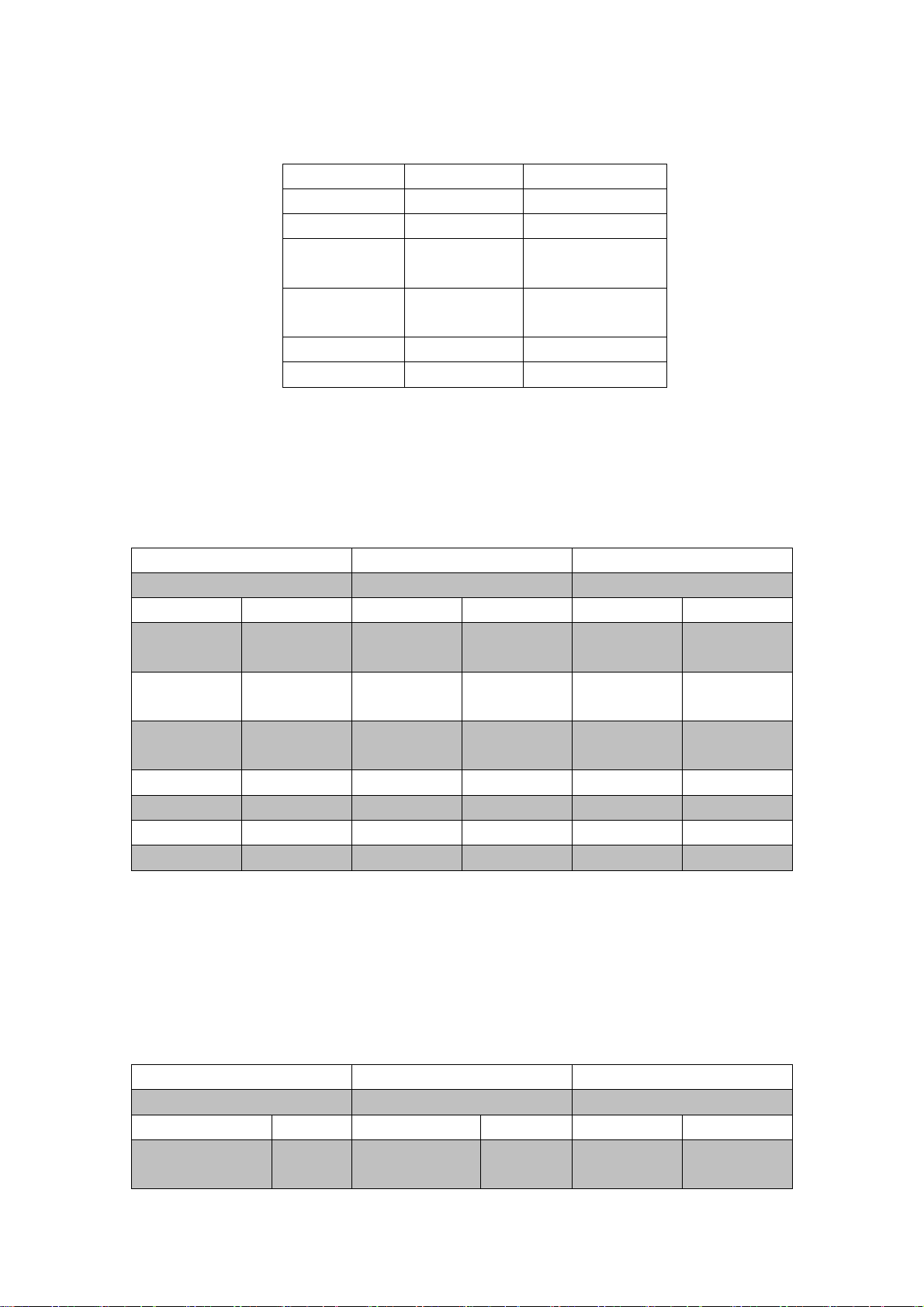
1.2 Driver and motor model reference
Server driver
model
Driver
specification
(output
voltage /
current)
Matched motor specification
Motor
flange(mm)
Maximum
rated power
(kW)
Maximum
rated torque
(Nm)
Maximum
rated speed
(rev/min)
SC1-3003
220V/2.8A
60
0.4
1.27
3000
SC1-3010
220V/3A
80
0.75
2.39
3000
SC1-3011
220V/4.4A
80
1.0
4
2500

6
1.3 Driver appearance
Chapter 2 Installation
2.1 Notice
Please pay special attention to the following:
1) The connection between the driver and the motor cannot be tightened;
2) When fixing the driver, it must be locked at each fixed position;
3) The motor shaft must be in good alignment with the shaft of the equipment;
4) If the drive and motor are connected more than 20 meters, please thicken the UVW cable and
the encoder cable;
5) The four screws of the motor must be locked.
2.2 Storage condition
This product must be placed in its packaging before installation. If not use now,please pay
attention to the following instruction of storage:
1) Must be placed in a dust-free and dry place.
2) The temperature of storage must be in the range of -20 degree to +65 degree.
Power Indicator
Servo ON indicator
Cooling base, High temperature
during work,don’t touch
220V/50/60Hz
L1 L2 when single phase
L1 L2 L3 when three phase
Motor UVW
Regenerative resistor
Protective grounding
5-digit LED display
Key input
Communication port
Signal terminal of input
and output
Encoder terminal

7
3) The relative humidity of the storage location must be in the range of 0% to 90% without
condensation.
4) Avoid storage in environments containing corrosive gases and liquids.
5) It is best to store it properly on a shelf or countertop.
2.3 Installation environmental conditions
The using temperature range of our driver is 0 degree to 55 degree.If the temperature exceeds 45
degree, please place it in a well-ventilated place. Long-term operation is recommended at an the
temperature below 45 degree to ensure product reliability. If it’s installed in a power distribution
box,please assure that all internal electronic devices are not at risk of overheating. Also, please pay
attation to the vibration of machine. In addition to this, the conditions used include:
1) no high heat device around;
2) free of water droplets, vapors, dust and oily dust;
3) non-corrosive, flammable gases and liquids;
4) non-floating dust and metal particles;
5) Strong and vibration-free places;
6) without electromagnetic noise interference.
2.4 Installation direction and space
Please install the driver correctly according to the following picture, so as not to cause
unnecessary loss!
Right installation
Wrong installation

8
Please install in strict accordance with the specified installation spacing to ensure good ventilation
and heat dissipation.
Chapter 3 Wiring
3.1 Servo system schematic
>100mm
>100mm
Input and output terminals are
connected to PLC and analog
and pulse input
再生
电阻
地
Voltage
>50mm
>50mm
>50mm

9
3.2 Driver terminal and connection instructions
Terminal symbol
Name
Fuction
L1 L2 L3
R S T
Power terminal
Three/single phase 220V to 240V 50/60Hz. (If
single phase connect L1 & L2)
U V W
Motor power line
terminal
Connect with motor
P+ D C
Regenerative
braking resistor
Terminals
Connected to the regenerative resistor, the external
resistor is connected between P+ and C
Ground terminal
Connect to the power ground wire, ground
protection
CN1
Input and output
terminal
Input and output signal DI/DO wiring
CN2
Encoder terminal
Encoder terminal connected to motor encoder
COM1
Communication
port
Communicate with the host computer to support
485, RS232 communication
3.3 Braking resistor
Function : Discharge, to ensure the stability of the DC bus voltage. In servo motor control, the
back EMF generated by the motor is feed back to the bus capacitor, causing the bus voltage to rise.
When the voltage reaches the alarm limit (P0-14), the servo output alarm EN-03
Therefore, to ensure that the bus voltage does not exceed the voltage limit of device, the system
will conduct the discharge terminal when the voltage rises to the limit, and quickly balance the bus
voltage through the brake resistor.
Model selection:
Wiring terminals:
Servo series
Terminal
A/B/C series
P+ and C
E series
P+ and PB
Braking resistor model selection
Model
Output
current
Resistance
range
Power range
Recommended resistance value
CZ-A
13A
50~100Ω
》=100W
50Ω
CZ-B
30A
50~100Ω
》=200W
50Ω
CZ-C
40A
40~50Ω
》=500W
40Ω
CZ-E
50A
25~35Ω
》=1000W
35Ω
CZ-E
75A
20~35Ω
》=2000W
35Ω
Notice: For 220V servo, discharge voltage is 370V;and 380V discharge voltage is 700V; The
discharge current can not exceed 80% of maximum output current when resistance value is
selected; more power can be selected when starting and stopping frequently

10
3.4 Brake wiring
In a vertical mechanism, when power off or the servo is enable OFF, the workpiece will fall due to
gravity.So we need to use the servo motor with brake to avoid it’s slide down
Parameter setting:P5-24 set 0084;P5-26 set 0000;then power off the driver and restart.If the
workpiece is slightly down when enable OFF, increase P5-06 around 100ms or decrease the value
of P5-08, and fine tune according to the situation; when the speed is lower than the setting value
of P5-07, the brake is on.
3.5 CN1 input and output signal line and terminal description
3.3.1 CN1 connector terminal arrangement is as follows (face to solder tab):
Pin
Name
Signal
Pin
Name
Signal
Pin
Name
Signal
P
in
Name
Signal
1
SO1
Output1
2
6
SI-COM
Input Public
side 24V
2
SO1-CO
M
Output
10V
3
SO2
Output2
27
SI-COM
Input
Public
side 24V
2
8
SI1
Input
1
4
SO2-CO
M
Output
20V
5
SO3
Output3
29
SI2
Input 2
3
0
SI3
Input
3
6
SO3-CO
M
Output
30V
7
SO4
Output4
31
SI4
Input 4
3
2
SI5
Input
5
8
SO4-CO
Output
9
SO4
Output4
33
SI6
Input 6
3
SI7
Input
24
25
2
49
1
27
50
26

11
3.3.2 Input and output signal wiring
The input and output signals of the servo unit and its connection to the host device:
(1) Analog input circuit
Application mode: Speed control (analog voltage) P0-01: parameter setting 4
Torque Control (Analog Voltage) P0-01: Parameter setting 2
Circuit parameters: Input impedance RI = 13KΩ
Input voltage Vmax<=10V
(2) Pulse input circuit
M
40V
4
7
10
SO4-CO
M
Output
40V
11
35
AGND
Input
negative
of analog
3
6
AGND
Input negative
of analog
12
13
37
V-REF
Speed
analog
3
8
T-REF
Torque
analog
14
15
PULS-
Pulse
Input
39
-10V
Output
4
0
+10V
Output
16
17
PULS +5V
Pulse 5V
41
485 A
Bus
communic
ation
4
2
485 B
Bus line
Communicatio
n
18
19
PULS
+24V
Pulse24
V
43
4
4
20
21
DIR-
Direction
45
B+
Encoder
feedback
4
6
B-
Encoder
feedback
22
ZOC-
Z pulse
Negative
electrode
23
DIR +5V
Direction
5V
47
A+
Encoder
feedback
4
8
A-
Encoder
feedback
24
ZOC+
Z pulse
negative
electrode
25
DIR +24V
Direction
24V
49
Z+
Encoder
feedback
5
0
Z-
Encoder
feedback
Host device
Analog input circuit
Servo driver
+10V
-10V
T-REF Torque analog input
V-REF Speed analog input
AGND

12
Application mode: Position control (external pulse) P0-01 Parameter setting 6
Speed Control (External Pulse) P0-01 Parameter setting 7
(3) Input and output signal circuit
Optocoupler output circuit
Host device
Servo driver
Host device side
Pulse command input wiring
Servo driver
PULS
PULS+24V
DIR+24V
DIR
3.3K
3.3K
+24V
0V
Y0
COM0
Y1
COM1
Collector open drain input
SI-COM
SI
3.3K
+24V
0V
Y0
COM
Host device side
Servo driver

13
3.6 CN2 encoder wiring and terminal description
CN2 connector terminal arrangement is as follows (face to solder tab):
3.7 Communication port
COM connector terminal arrangement is as follows(face to solder tab):
Driver
interface
Name
Driver
interface
Name
Driver
interface
Name
Driver
interface
Name
1
A+
2
A-
11
U+
12
U-
3
B+
4
B-
13
V+
14
V-
5
Z+
6
Z-
15
W+
16
W-
7
5V
8
5V
17
GND
18
GND
9
5V
10
5V
19
GND
20
GND
9
10
20
1
12
11
2
19
Relay input
+24V
0V
Y0
3.3K
COM
SI
SI-COM
Host device side
Servo driver
14
3.8 MODBUS Protocol
1. Servo single register value setting:
Sending
Servo correct feedback
Servo error feedback
Hexadecimal
Hexadecimal
Hexadecimal
Station No.
01
Station No.
01
Station No.
01
Function
code
06
Function
code
06
Function
code|0x80
86
Starting
address H
00
Starting
address H
00
Error code
**
Starting
address L
01
Starting
address L
01
CRCH
**
Set value H
00
Set value H
00
CRCL
**
Set value L
05
Set value L
05
CRCH
**
CRCH
**
CRCL
**
CRCL
**
Eg:Set P0-01 data Use the default parameters of the servo the station number is 1
sending data:01 06 00 01 00 05 CRCH CRCL
Reading correct feedback data:01 06 00 01 00 05 CRCH CRCL
Reading error feedback data:01 86 ** CRCH CRCL //** error code
2. Continuously setting servo multiple register values:
Sending
Servo correct feedback
Servo error feedback
Hexadecimal
Hexadecimal
Hexadecimal
Station No.
01
Station No.
01
Station No.
01
Function code
10
Function code
06
Function
code|0x80
86
Pin
Name
Instruction
1
A
RS485-A
3
B
RS485-B
4
RXD
RS232 receiving
terminal
5
TXD
RS232 sending
terminal
8
GND
RS232 ground
2
GND
Downloader

15
Starting address
H
00
Starting
address H
00
Error code
**
Starting address
L
01
Starting
address L
01
CRCH
**
Number of
registers H
00
Number of
registers H
00
CRCL
**
Number of
registers L
05
Number of
registers L
05
Number of bytes
02
CRCH
**
Register value H
**
CRCL
**
Register value L
Register value H
Register value L
CRCH
CRCL
Eg:Continuous setting 2 data values Set P0-01 to 5 Set P0-02 to 6 Station number is 1
sending data:01 10 00 01 00 02 00 05 00 06 CRCH CRCL
Reading correct feedback data:01 10 00 01 00 02 CRCH CRCL //** **data
Reading error feedback data:01 90** CRCH CRCL //** error code
3.Read Servo Register Value:
Sending
Servo correct feedback
Servo error feedback
Hexadecimal
Hexadecimal
Hexadecimal
Station No.
01
Station No.
01
Station No.
01
Function
code
03
Function
code
03
Function
code|0x80
83
Starting
address H
00
Data length
02
Error code
**
Starting
address L
01
Data 1H
**
CRCH
**
Reading
quantity H
00
Data 1L
**
CRCL
**
Reading
quantity L
01
Data 2H
CRCH
**
Data 2L
CRCL
**
…
…
…
CRCH
**

16
CRCL
**
Eg:Reading P0-01 data Use the default parameters of the servo the station number is 1
sending data:01 03 00 01 00 01 CRCH CRCL
Reading correct feedback data:01 03 02 ** ** CRCH CRCL //** **data
Reading error feedback data:01 83 ** CRCH CRCL //** error code
Chapter 4 Panel Display and Operation
4.1 Panel introduction
Name
Function
STA/ESC
State switching, return
INC
Increase display data value,continous increase for
long press
DEC
Reduce display data value,continous reduce for long
press
ENT
Confirmation key, enter to setting parameters, view
parameters
SHIFT
shift
COM
Custom key
Power indicator
POWER
It’s ligh up when power on
Running indication light
RUN
Light up while the servo is running(S-ON Signal is
valid)
运行
RUN
E
D
电源
POWER
C
A
B
STA
ESC
COM
ENTER
SHIFT
INC
DEC

17
4.2 basic state switching
After pressing the STA/ESC key, the states can be switched as the upper figure showed
Parameter setting P0-00
Monitoring status Un-00
Alarm status En-XX
Accessibility Help
a.System Information View F0
b.Torque / speed command offset adjustment F1
Select F1-00 into the analog offset automatic adjustment feature , this time status display : F--, and - blink ,
about 5 seconds or so current detection offset automatic adjustment is completed, then display :F-F, inform the user
automatically adjusting complete.
Select F1-01 to enter the torque control analog offset automatic adjustment function (same operation)
c.F2 alarm View
d.Serial External Communications F3
Select F3-00 into the external serial communication mode , prompting COE, which is in an external monitor
status , serial port 1 (COM1) effective monitoring panel failure , this time, through the host computer (PC) of the
servo unit for tuning. Press the STA / ESC to return , and exit the COE, restore panel monitor .
e.Restore factory defaults F4
A
speed control:Synchronous speed detection
Position control: end of positioning
B
Speed control: torque limit
Position control: approaching
C
Speed control: rotation detection
Position control: rotation detection
D
Speed control: zero clamp
E
Speed control: speed limit
Running display
status
Parameter setting
status
Monitor display
status
Auxiliary Function

18
In bb condition,select F4-00 to enter the factory default settings , suggesting rEt--, stay in a wait state ,
press Ent settings, wait for showing rEt-E, then power off and power on,now finish restore the factory defaults.
f. J-OG mode
In bb condition,choose F5-00,press shift to 0 blink,press Ent into show J-OG,press INC to show P motor
running,press DEC to show N motor reverse running,short press motor jog,long press motor continuous
running,jog speed setting:P3-04.
g. Panel give enable signal S-ON,F6-00
In bb condition,short press STA,show F0-00,press INC,show F6-00,press shift to 0 blink,press Ent to show
E-,press shift again, E-n driver enable,get in and press DEC to cancel enable;can used for correct current,set P0-00
to 2,P0-01,give enable signal about 10 seconds,compelet the current examine;different from F1-00 analog current
check,here correct the UVW control current calibration
h. Program download
Long press ESC before power on,then power on and shows P000,now can use the series to download
program(COM port 2pin short-circuited with 8pin)
4.3 Parameter setting
Here’s the example of change the parameter of P2-09 from 2000 to 1000.
1. Press the STATUS/ESC key to enter the parameter setting state,then press the ENTER
key.
2.At this time, the second LED from left flashes, press INC or DEC key to modify the group
number , change it to 3, then short press ENTER to confirm .
3.At this time, the right number two digital tube flashes, press INC, DEC or ENTER key to
select the number 9 , long press the ENTER key for confirm.
4.Now, display the data in P2-09 , the lowest position "0 " flashes , then short press the ENTER key
allows the blinking one move one bit to the left. Press INC , DEC or ENTER key , the data is
changed to 1000 , long press ENTER to confirm the modification.
Thus, the user parameter P3-09 changes 2000 to 1000. Need to further change the value , repeat
the above operations of 2 to 4 .
5.Press the STATUS / ESC key to return to the other group or state you want to do modify

19
4.4 Brief description of code display
code
Display content
In standby mode
Servo OFF status (The motor is powered off)
Running
Servo enable(The motor is powered on)
Prohibition of forward rotation
P-OT OFF status. Please refer to "Overtravel Setting".
Prohibition of reverse rotation
N-OT OFF status. Please refer to "Overtravel setting"
4.5 Restore factory setting
Restore all user parameters to factory settings, including P0-11 motor code
Please confirm the parameters before reseting, or it will not be able to recover.
When need to restore the factory settings?
Alarm EN-02, parameter damage
An abnormal operation caused by setting parameters during debugging
There is a command send to motor,but it does not run, no alarm, check if P3-09
value is 0, if it is, then restore the factory setting.
Steps:
1. Turn off the enable signal first.(External enable: Please disconnect the external signal;
Internal power-on enable: set P0-01 to n.0101 and then power off and restart)
2. Enter F4-00
(Refer to e in section 4.2)
3. Check the motor parameters (take the drive SC1-3010/AMS80-02430Z as an
example)
a) Check motor code power code F0-00 :display 750 means 750W
b) Check motor model code F0-24: shows 02430 indicates 2.4N·M, 3000 rpm
c) Check input voltage level and flange F0-25:display 2080 indicates 220V, 80
flange
If the alarm is EN-02, also need current check, please refer to section 4.6

20
4.6 Current check
Function: Eliminate motor control instability or abnormal noise caused by inaccurate current
sampling,whcih caused by hardware drift
Method:
Turn off the enable signal first.
(External enable: Please disconnect the external signal; Internal power-on enable: set
P0-01 to n.0101 and then power off and restart)
Setting parameters
(Setting P0-00 to 2; P0-01 to 0)
Enter F6-00 to set the enable signal
(In the bb state, press the STA button shortly, when F0-00 appears, press INC, then
F6-00 appears, press shift to 0 to flash, press Ent to display E-, then press shift again
to display E-n drive enable; Wait 10 seconds to complete the verification, press DEC
to cancel the enable)
Chapter 5 Trial and tunning steps
5.1 No-load detection
To avoid damage the servo driver or mechanism, first remove the load connected to the servo
motor (including the coupler and other accessories).Then doing testing according to normal
operating procedures.After testing is OK,can connect with load.
Test items:
Pre-boot detection
(cut off the power supply)
Ensure that the servo driver and motor have no mechanical
damage
Ensure that the terminal wiring is secure and there is no danger
of electric shock
Ensure that the wiring is complete and correct
Ensure that the external input signal meets the standard
Guarantee no other errors or dangers
Running time detection
(power on)
Ensure that the wires are not pulled or abrasion during operation
Does the motor have strong shake or abnormal sound?
Does the indicator light normal?
Is there any alarm display? If there is an alarm, please first find
the alarm code in the alarm parameter table, and then clear the
alarm after eliminating the alarm factor.
When modifying parameters, please confirm the parameter
modification and effective time.
Check if the device execute according to preset modes and
parameters
This manual suits for next models
2
Table of contents


