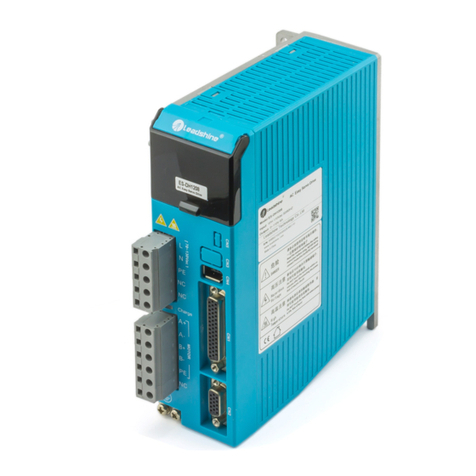
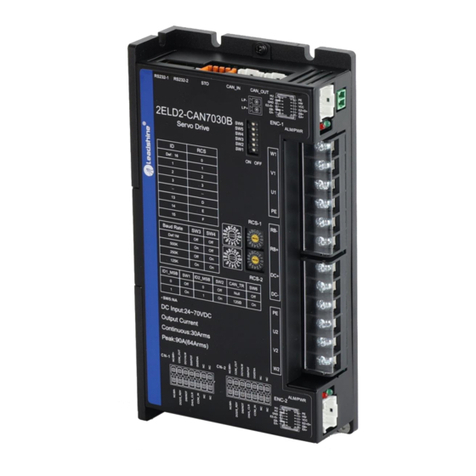
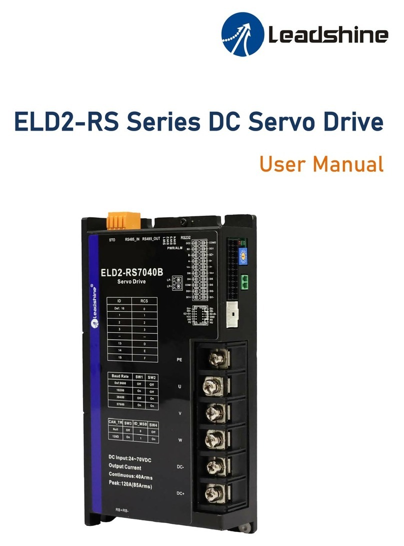
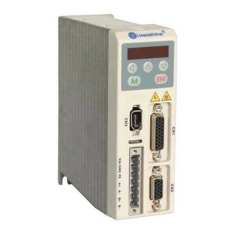
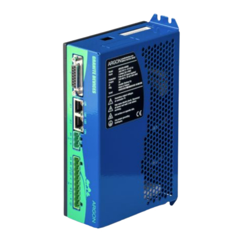
CS-D508 Closed-loop Stepper Drive User Manual
Motion Control Products Ltd. Tel.: (+44) 01202 599922 www.motioncontrolproducts.com
Table of Contents
1. Introduction.......................................................................................................................................................1
1.1 Features........................................................................................................................................................1
1.2 Applications..................................................................................................................................................1
2. Specifications.....................................................................................................................................................2
2.1 Electrical Specifications................................................................................................................................2
2.2 Environment.................................................................................................................................................2
2.3 Mechanical Specifications............................................................................................................................2
2.4 Elimination of Heat ......................................................................................................................................3
3. Connections / Pin Assignments and LED Indication ............................................................................................3
3.1 P1 - Control and Digital Output Connections...............................................................................................3
3.1.1 Pin Assignments of P1 .......................................................................................................................3
3.1.2 Typical Control and Fault Output Connections..................................................................................5
3.2 Connector P2 - Encoder Connection............................................................................................................5
3.3 Connector P3 - Motor Connection...............................................................................................................5
3.4 Connector P4 – Power Supply Connection ..................................................................................................6
3.5 Connector P5 – RS232 Conenction ..............................................................................................................6
3.6 Status LED Lights ..........................................................................................................................................6
4. Motor Selection ....................................................................................................................................................6
5. Power Supply Selection ........................................................................................................................................6
5.1 Regulated or Unregulated Power Supply.....................................................................................................7
5.2 Power Supply Sharing ..................................................................................................................................7
5.3 Selecting Supply Voltage..............................................................................................................................7
6. DIP Switch Configurations ....................................................................................................................................7
6.1 Microstep Resolution (SW1-SW4)................................................................................................................8
6.2 Other DIP Switch Settings (SW5-SW8).........................................................................................................8
7. Typical Connection................................................................................................................................................8
8. Sequence Chart of Control Signals .......................................................................................................................9
9. Fault Protections.................................................................................................................................................10
10. Software Configuration.....................................................................................................................................10
11. Accessories........................................................................................................................................................11
12. Troubleshooting................................................................................................................................................11
13. Warranty ...........................................................................................................................................................13
Appendix A. Leadshine CS-D508 Compatible Stepper Motors...........................................................................14
Appendix B. Powering a Third Party Motor with CS-D508.................................................................................15


