INGENIA Everest XCR User manual

INGENIA-CAT S.L.
8-14 MARIE CURIE, ADVANCED INDUSTRY PARK
08042 BARCELONA
Everest XCR - Product Manual
Edition 10/15/2018
For the most up to date information visit the online manual.

1. Table of Contents
1. Table of Contents 2
2. General Information 3
2.1. Manual revision history ..................................................................................................................................3
2.2. Disclaimers and limitations of liability ..........................................................................................................3
2.3. Contact ............................................................................................................................................................3
3. Safety Information 4
3.1. About this manual...........................................................................................................................................4
3.2. Warnings..........................................................................................................................................................4
3.3. Precautions .....................................................................................................................................................4
4. Product Description 5
4.1. Everest XCR part numbering ..........................................................................................................................5
4.2. Specifications..................................................................................................................................................6
4.3. Thermal specifications ...................................................................................................................................9
5. Connectors Guide 13
5.1. Supply............................................................................................................................................................13
5.2. Motor.............................................................................................................................................................13
5.3. Feedback connector ..................................................................................................................................... 14
5.3.1. Mating terminals and cables common for all signal connectors ...............................................................15
5.4. Input / Outputs connector............................................................................................................................18
5.5. EtherCAT connectors ....................................................................................................................................20
6. Signalling LEDs 22
6.1. Power and Operation Signalling LEDs .........................................................................................................22
6.2. EtherCAT Signalling LEDs .............................................................................................................................22
7. Dimensions 24
8. EtherCAT specifications 25
9. Service 26

Everest XCR - Product Manual|General Information
INGENIA |10/15/2018 3
2. General Information
2.1. Manual revision history
v1 Preliminary draft.
Revision Release Date Changes PDF
For the most up to date information use the onlineProduct Manual. The PDF manual is generated only after major
changes.
Please refer toproduct hardware revisionsfor information on previous hardware revisions and changes.
2.2. Disclaimers and limitations of liability
The information contained within this document contains proprietary information belonging toINGENIA-CAT S.L..
Such information is supplied solely for the purpose of assisting users of the product in its installation.
INGENIA-CAT S.L.rejects all liability for errors or omissions in the information or the product or in other
documents mentioned in this document.
The text and graphics included in this document are for the purpose of illustration and reference only. The
specifications on which they are based are subject to change without notice.
This document may contain technical or other types of inaccuracies.The information contained within this
document is subject to change without notice and should not be construed as a commitment byINGENIA-CAT
S.L..INGENIA-CAT S.L.assumes no responsibility for any errors that may appear in this document.
Some countries do not allow the limitation or exclusion of liability for accidental or consequential damages,
meaning that the limits or exclusions stated above may not be valid in some cases.
2.3. Contact
INGENIA-CAT S.L.
8-14 Marie Curie
Advanced Industry Park
08042 Barcelona
Spain
Telephone: +34 932 917 682
E-mail:[email protected]
Web site:www.ingeniamc.com

Everest XCR - Product Manual|Safety Information
INGENIA |10/15/2018 4
3. Safety Information
3.1. About this manual
Read carefully this chapter to raise your awareness of potential risks and hazards when working with the Everest
XCR Servo Drive.
To ensure maximum safety in operating the Everest XCR Servo Drive, it is essential to follow the procedures
included in this guide. This information is provided to protect users and their working area when using the Everest
XCR Servo Drive, as well as other hardware that may be connected to it. Please read this chapter carefully before
starting the installation process.
3.2. Warnings
The following statements should be considered to avoid serious injury to those individuals performing the
procedures and/or damage to the equipment:
•To prevent the formation of electric arcs, as well as dangers to personnel and electrical contacts, never
connect/disconnect the Everest XCR Servo Drive while the power supply is on.
• Disconnect the EverestServo Drive from all power sources before proceeding with any possible wiring
change.
•After turning off the power and disconnecting the equipment power source, wait at least 10 seconds before
touching any parts of the controller that are electrically charged or hot.
3.3. Precautions
The following statements should be considered to avoid serious injury to those individuals performing the
procedures and/or damage to the equipment:
• The EverestServo XCR Drive components temperature may exceed 100 ºC during operation.
• Some components become electrically charged during and after operation.
•The power supply connected to this controller should comply with the parameters specified in this
document.
• When connecting the EverestServo XCR Drive to an approvedpower source, do so through a line that is
separate from any possible dangerous voltages, using the necessary insulation in accordance with safety
standards.
•High-performance motion control equipment can move rapidly with very high forces. Unexpected motion
may occur especially during product commissioning. Keep clear of any operational machinery and never
touch them while they are working.
•Do not make any connections to any internal circuitry. Only connections to designated connectors are
allowed.
•All service and maintenance must be performed by qualified personnel.
• Before turning on the EverestServo XCR Drive, check that all safety precautions have been followed, as well
as the installation procedures.

Everest XCR - Product Manual|Product Description
INGENIA |10/15/2018 5
4. Product Description
PRELIMINARY
Everest XCR is a compact, smart digital servo drive. Thanks to its small size and rugged design it can be mounted
virtually anywhere: collaborative robot joints, wearable robots, unmanned ground or aerial vehicles as well as
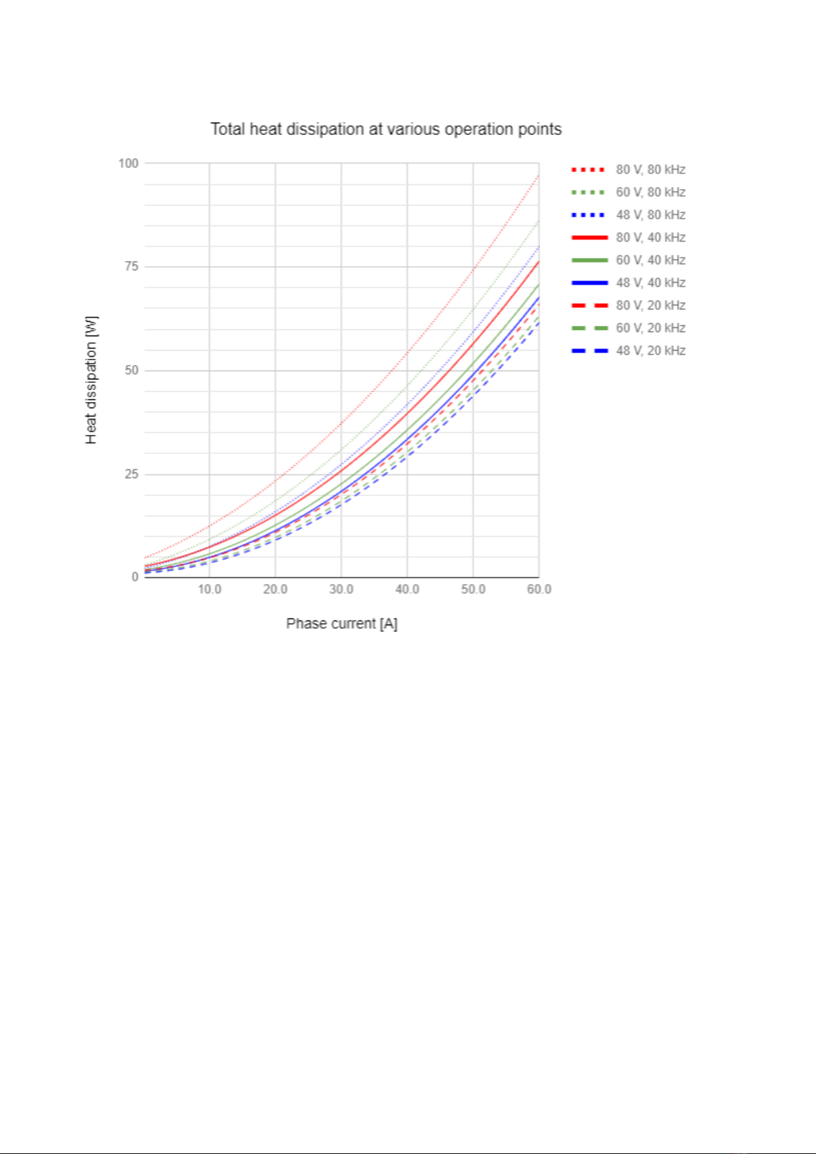
inside motors. The drive features best in class energy efficiency thanks to the latest GAN technology. At 30 ARMS (42
A amplitude) 80 VDC it generates just 20 W of total heat dissipation exceeding by far any comparable servo drive.
The standby power losses of Everest XCR are minimal, even using EtherCAT, the consumption is less than 2.5 W.
Everest will save energy on your project and provide longer battery times.
The control loops have sampling times that exceed the electrical and mechanical time constants of almost any
motor.Up to 14 µs(75 kHz)current loop and 40 µs(25 kHz) position and velocity loops.The bandwidth of the
control system will only be limited by the physical limits of the system and the feedback. Configurable digital filters
offer extra flexibility. In addition, control algorithms can be programmed and executed real time on the drive.
Power stage PWM frequency can be adapted to each application, with a minimum 10 kHz for low electrical noise
and power losses and a maximum of 100 kHz for low inductance motors. Current gain can also be configured on 4
different ranges allowing the same drive and part number to used for various motor sizes and thus simplifying
stocking and complexity in your application.
The Everest XCR can close loops with a Digital Incremental Encoder, Dual BiSS-Cencoder and Digital
Halls.Everything can be easily configured with the new INGENIA MotionLab 3.
Everest XCR include compliant EtherCAT & CANopen communication. The drive can be accessed from a standard
EtherNET port for configuration.
The Everest XCR can be operated with a single power supply on its full operating range and includes an additional
logic supply up to 50 V. It includes 4 digital inputs and 4 digital outputs, a dedicated brake output, motor
temperature sensing input and a 16 bit ±10 V analog input to interface with load cells and torque meters.
The driver has built-in safety torque off (STO) and includes several safety protections to protect against most issues
like short-circuits, temperature and voltage based current foldback, overtemperature, overvoltage, and has
industry grade EMC and ESD inmunity.
PRELIMINARY
4.1. Everest XCR part numbering
Everest XCR is available on a single part number. Rated at 30 ARMS continuous current and an operation voltage
between 8 VDC to 85 VDC. Variable gain current sense amplifier and 16 bit ADC allow controlling low current motors.

Everest XCR - Product Manual|Product Description
INGENIA |10/15/2018 6
Everest XCR EVE-30/100-XCR
Product Ordering part number Status Image
4.2. Specifications
A list of features of the Everest XCR Servo Drive is shown next. For further details, please check theOperational
characteristicssection below.
Electrical and power specifications
Minimum power supply voltage 8 VDC
Maximum absolute power supply
voltage
80 VDC (continuous)
85 VDC (peak 100 ms)
Recommended power supply voltage 12 VDC ~ 72 VDC
This voltage range ensures a safety margin including power supply tolerances and
regulation.
Logic power supply voltage (optional) 8 to 50 VDC
Providing the logic supply is optional, as the drive is supplied from the DC bus (single
supply) on its full operating voltage range.
Nominal phase continuous current
(BLDC mode)
30 ARMS
Nominal phase continuous current (DC
mode)
30 ADC
Maximum phase peak current 60 ARMS @ 5 sec
Active current limiting based on power stage and motor temperature.
PRE-PROD

Everest XCR - Product Manual|Product Description
INGENIA |10/15/2018 7
Efficiency (at nominal conditions) > 99%
Bus voltage utilization > 96%
Motion control specifications
Standby power ≤2.5 W
Supported motor types •Rotary brushless (sinusoidal commutation only)
Power stage PWM frequency 10 kHz, 20 kHz, 50 kHz & 100 kHz user configurable
Current sensing 16 bit ADC resolution. Accuracy is ± 1% full scale.
Current gain is configurable in 4 ranges.
Current sense range (configurable 4
gain levels)
±87.7A, ±47.7A, ±20.6A, ±13.8A
Current sense resolution
(configurable)
2.676 mA/count, 1.46 mA/count, 0.63 mA/count, 0.42 mA/count
Max. Current loop bandwidth TBD
Feedbacks •Digital Hall
•Quad. Incremental encoder / BiSS-C
•BiSS-C
Supported target sources •Network communication
Control modes Cyclic Synchronous Position, Cyclic Synchronous Velocity, Cyclic
Synchronous Torque
Profile Position, Profile Velocity, Profile Torque, Interpolated Position,
Homing
Inputs/outputs and protections
Inputs and outputs General purpose:
•4 x non-isolated single-ended digital inputs - 5 V logic level. 3.3V
ready.
•1 x non-isolated single-ended digital outputs - 5 V logic level
(continuous short circuit capable with 470 Ωseries resistance.
•1 x ±10V fully differential analog input 16 bit. Typ. for load cells
and closing torque loop.
Dedicated:
•1 x Motor temperature analog input (with 1.65 kΩpullup to 3.3V)
•2 x isolated STO dedicated inputs.

Everest XCR - Product Manual|Product Description
INGENIA |10/15/2018 8
Protections •User configurable:
•DC bus over-voltage
•DC bus under-voltage
•Drive over-temperature
•Drive under-temperature
•Over-current
•Overload (I2t)
• Short-circuit protections:
•Phase to DC bus
•Phase to phase
•Phase to GND
•Motor over-temperature
•Motor under-temperature
•Mechanical limits for homing functions
•Hall sequence / combination error
•Following error
Motor brake 1 A 50 V Dedicated brake output. Open drain with re-circulation diode
to +V_LOGIC.
Brake enable and disable timing can be configured accurately.
PWM modulation available to reduce brake voltage and power consumption.
Communications for Operation
EtherCAT CANopen over EtherCAT (CoE)
File over EtherCAT (FoE)
Ethernet over EtherCAT (EoE)
CANopen (Software selectable) CiA-301, CiA-303, CiA-305, CiA-306 and CiA-402 (3.0) compliant
Environmental conditions
Cold plate Yes
Cold plate temperature •-40 ºC to +85 ºC full current
•+85 ºC to +95ºC derated current
Storage:
-55 ºC to +100 ºC
Maximum humidity 5% - 85% non-condensing
ESD and EMC inmunity ESD immunity IEC 61000-4-2: ± 30 kV contact discharge , ± 30 kV air
discharge
EFT immunity IEC 61000-4-4: > 40 A
Surge immunity: IEC 61000-4-5 IPPM > 8 A

Everest XCR - Product Manual|Product Description
INGENIA |10/15/2018 9
Mechanical specifications
Dimensions 42.1 mm x 29.1 mm x 23.1 mm
Dimensions include mating connectors
Weight TBD
Certifications
Certification CE, RoHS
STO SIL3 (certification pending)
4.3. Thermal specifications
The following diagram depicts the general dissipation model and the equivalent thermal model.
To ensure a proper performance of Everest XCR, the housing temperature must be held below 85 ºC. The
following figures show how to calculate the required heatsink
The following figure depict the power losses of Everest Core for different phase current values in RMS value. To
obtain the equivalent current in amplitude, multiply by 1.41.

Everest XCR - Product Manual|Product Description
INGENIA |10/15/2018 10
Note this is theoretical. The maximum heatsink temperature must be kept at 85ºC.

Everest XCR - Product Manual|Product Description
INGENIA |10/15/2018 11
For ensuring a good thermal coupling between Everest and the heatsink, a good quality thermal pad is required.
For example, a thermal sheetTGX-150-150-0.5-0,which (for Everest XCR contact surface) has an estimated
thermal impedance ofRth(c-h) =0.2 K/W
Considering the previous parameters, themaximum thermal impedance heatsink-to-airrequired can be
calculated as:

Everest XCR - Product Manual|Product Description
INGENIA |10/15/2018 12

Everest XCR - Product Manual|Connectors Guide
INGENIA |10/15/2018 13
5. Connectors Guide
5.1. Supply
P1 connector
2.6 mm diameter gold plated solder pads or flying leads option. Pad pitch is 5.08 mm.
Pin Signal Function
1 POW_SUP Power supply positive
2 GND_P Power supply return
Notes
Recommended section wire is 2.5 mm2~ 5.3 mm2, AWG 10 ~ AWG 13 for applications working at maximum
current. Adapt the cable diameter to your current needs.
It is recommended to use flexible silicone cables to ensure low mechanical stress to the board as well as high
temperature ratings (≥110 ºC). Diameter of the cable Jacket (insulator) should be less than 5.08 mm to prevent
collision between wires.
5.2. Motor
P2 connector
2.6 mm diameter gold plated solder pads or flying leads option. Pad pitch is 5.08 mm.
Pin Signal Function
1 PH_A Motor phase A
2 PH_B Motor phase B
3 PH_C Motor phase C
4 PE Protective earth connection, internally connected to standoffs and drive cold
plate.
Notes
Recommended section wire is 2.5 mm2~ 5.3 mm2, AWG 10 ~ AWG 13.
For long cables it is essential to use a shielding connected to protective earth at both ends of the cable.

Everest XCR - Product Manual|Connectors Guide
INGENIA |10/15/2018 14
5.3. Feedback connector
J1 connector
20 pins 2 row Pico-Clasp 1 mm pitch header. Molex 501190-2027
Pin Signal Function
1 +5V_OUT 5 V 200 mA total max. Short circuit protected. Pins 1, 9, 14 are internally
connected.
2 GND_D Digital signal ground
3 ENC_A+/DATA2+ Differential digital encoder: A+ input
Single ended digital encoder: A input
Absolute encoder 2: Data +
4 ENC_B+ Differential digital encoder: B+ input
Single ended digital encoder: B input
4 ENC_A-/DATA2- Differential digital encoder: A- input
Single ended digital encoder: Leave unconnected
Absolute encoder 2: Data -
6 ENC_B- Differential digital encoder: B- input
Single ended digital encoder: Leave unconnected
7 ENC_Z+/CLK+ Differential digital encoder: Index+ input
Single ended digital encoder: Index input
Absolute encoder 2: Clock +
8 ENC_Z-/CLK- Differential digital encoder: Index- input
Single ended digital encoder: Leave unconnected
Absolute encoder 2: Clock -

Everest XCR - Product Manual|Connectors Guide
INGENIA |10/15/2018 15
9 +5V_OUT 5 V 200 mA total max. Short circuit protected. Pins 1, 9, 14 are internally
connected.
10 GND_D Digital signal ground
11 HALL_1 Digital hall sensor input 1
12 HALL_2 Digital hall sensor input 2
13 HALL_3 Digital hall sensor input 3
14 +5V_OUT 5 V 200 mA total max. Short circuit protected. Pins 1, 9, 14 are internally
connected.
15 GND_D Digital signal ground
16 DATA+ Absolute encoder DATA postive signal input
17 CLK+ Absolute encoder CLK positive signal output
18 DATA- Absolute encoder DATA negative signal input. For single ended absolute
encoders with TTL or CMOS levels leave this pin floating and connect the signal
to DATA+.
19 CLK- Absolute encoder CLK negative signal output. For single ended absolute
encoders with TTL or CMOS levels leave this pin floating and connect the clock
to CLK+.
20 PE Protective earth connection, internally connected to standoffs and drive cold
plate.
Description Molex Pico-Clasp™1.0 mm pitch 20 position dual row receptacle with locking ramp
Image
Part number Molex 501189-2010
Distributor code Digi-Key WM7929-ND
J1 mating connector
5.3.1. Mating terminals and cables common for all signal connectors
Everest XCR signal connectors are of Molex Pico-Clasp™family. All share the same crimp terminals and jumper
wires. Given the small size of the connectors, crimping must be done with appropriate tools and application guides

Everest XCR - Product Manual|Connectors Guide
INGENIA |10/15/2018 16
provided by Molex. Otherwise it is strongly recommended to buy pre-crimped jumper wires and connect to your
system using split (or butt) terminals. Spiral wraps are recommended to order and protect the thin wires.
J1, J2, J3, J4 Crimp terminals
Description Molex Pico-Clasp™crimp socket 28 AWG ~ 32 AWG selective gold plated
Image
Part number Molex 5011933000
Distributor code Digi-Key WM10136CT-ND
Crimper tool
Description Hand crimper tool 28-32 AWG
Part number Molex 63819-1500
Distributor code Digi-Key WM9018-ND
J1, J2, J3, J4 Crimped wires 150 mm
Description Molex Pico-Clasp™28 AWG black jumper lead socket to socket 150 mm lenght

Everest XCR - Product Manual|Connectors Guide
INGENIA |10/15/2018 17
Image
Part number Molex 079758-1016
Distributor code Digi-Key WM15694-ND
J1, J2, J3, J4 Crimped wires 300 mm
Description Molex Pico-Clasp™28 AWG black jumper lead socket to socket 300mm lenght
Image
Part number Molex 079758-1017
Distributor code Digi-Key WM15695-ND
Wiring accessory: Spiral wire wrap
Description Nylon spiral wrap abrasion resistant. Internal diameter:
2.41 mm, 3.18 mm expanded | 5.08 mm, 6.35 mm expanded
Image
Part number Alpha Wire SW20 NA005 | SW21 NA008
Distributor code Digi-Key ASW20-100-ND | ASW21-25-ND

Everest XCR - Product Manual|Connectors Guide
INGENIA |10/15/2018 18
Wiring accessory: wire to wire solder sleeve
Description Wire to Wire Solder Sleeve Heat shrinkable. Can be used to reliably connect pre-crimped
wires to specific sensor, feedback or other thin wires.
Image
TE B-155-9001
Distributor code Digi-Key A104848-ND
5.4. Input / Outputs connector
J2 connector
30 pins 2 row Pico-Clasp 1 mm pitch header. Molex 501190-3017
Pin Signal Function
1 STO_1 Safe Torque Off input 1 (positive, active from 5 V to 32 V, ISOLATED)
2 PE Protective earth connection, internally connected to standoffs and drive cold plate.
Can be used to connect cable shield.
3 STO_RET Safe Torque Off common (optocoupler LEDs cathode, ISOLATED).
4 NC Intentionally not connected.
5 STO_2 Safe Torque Off input 1 (positive, active from 5 V to 36 V, ISOLATED)
6 GND_D Digital signal ground
7 NC Intentionally not connected.
8 +5V_OUT +5 V output, can be used for STO circuit.

Everest XCR - Product Manual|Connectors Guide
INGENIA |10/15/2018 19
9 CAN_H CAN bus line dominant high
10 UART_3V3_RX Reserved
11 CAN_L CAN bus line dominant low
12 UART_3V3_TX Reserved
13 GND_D Digital signal ground
14 IN1 Digital input 1 (5V levels)
15 IN2 Digital input 2 (5V levels)
16 IN3 Digital input 3 (5V levels)
17 IN4 Digital input 4 (5V levels)
18 OUT1 Digital output 1 (5V levels)
19 OUT2 Digital output 2 (5V levels)
20 OUT3 Digital output 3 (5V levels)
21 OUT4 Digital output 4 (5V levels)
22 AN1+ Analog input 1 positive (±10V range)
23 BRAKE_N Brake output (open drain with PWM capability)
24 AN1- Analog input 1 negative (±10V range). Connect to GND if a single ended analog
input is used.
25 +LOG_SUP Logic supply, connected to pin 25. Can be used as brake positive
26 GND_D Digital signal ground
27 +LOG_SUP Logic supply positive.
Providing the logic supply is optional as the drive is powered from the DC bus on its
full operating voltage range. Logic supply can be used for brake or just to keep
communications alive while the power bus is off.
28 MOTOR_TEMP Motor temperature sensor input. A 1.65 kΩpull-up resistor to 3.3 V is included on
the drive.
29 GND_D Digital signal ground, logic supply negative
30 MOTOR_TEMP_RE
T
Motor temperature sensor return (refered to GND_D)
J2 mating connector
Description Molex Pico-Clasp™1.0 mm pitch 30 position dual row receptacle with locking ramp

Everest XCR - Product Manual|Connectors Guide
INGENIA |10/15/2018 20
Image
Part number Molex 501189-3010
Distributor code Digi-Key WM7930-ND
Crimp terminals
See table above.
5.5. EtherCAT connectors
J3 & J4 connector
5 pins 1 row Pico-Clasp 1 mm pitch header. Molex 501940-0507
Pin Signal Function
1 TX_D+ Transmit Data+ line. Colour typ:White -Orange
2 TX_D- Transmit Data- line.Colour typ:Orange
3 RX_D+ Receive Data+ line.Colour typ:White -Green
4 RX_D- Receive Data- line.Colour typ:Green
5 GND_ETH Connection for the EtherCAT cable shield. This pin is directly connected to the
chassis of the drive - PE.
J3 & J4 mating connectors with latch holder
Description Molex Pico-Clasp™1.0 mm pitch 5 position single row receptacle with Latch Holder.
Provides stronger locking performance and is easy to extract. Use this connector in case the
wiring ensures no strong pull will be performed to the cables, this could cause damage on
the PCB connector.
Other manuals for Everest XCR
2
Table of contents
Other INGENIA Servo Drive manuals

INGENIA
INGENIA Neptune User manual

INGENIA
INGENIA Triton Core User manual

INGENIA
INGENIA Jupiter JUP-20/80 User manual

INGENIA
INGENIA Nix series User manual

INGENIA
INGENIA Triton Go User manual

INGENIA
INGENIA Everest XCR User manual

INGENIA
INGENIA Everest CORE User manual

INGENIA
INGENIA Earth EAR-3/40-C-P User manual

INGENIA
INGENIA Pluto User manual

INGENIA
INGENIA Titan GO User manual