BRC Sequent 24 User manual

HANDBOOK
on SEQUENT 24
TA010976 - N. 1 - 17 - 11 - 2004
M.T.M. s.r.l.
Via La Morra, 1
12062 - Cherasco (Cn) - Italy
Tel. ++39 0172 48681
Fax ++39 0172 488237
2
INDEX
1. INTRODUCTION
1.1 WHAT IS SEQUENT 24?
1.2 MAIN DIFFERENCES WITH THE PREVIOUS SEQUENT SYSTEMS
2. UNDERSTANDING THE SEQUENT 24 SYSTEM
2.1 SEQUENT 24 ECU
2.2 CHANGEOVER SWITCH
2.2.1 CHANGEOVER SWITCH IN ITS PETROL POSITION
2.2.2 CHANGEOVER SWITCH IN ITS GAS POSITION
2.2.3 ERROR INFORMATION
2.3 GENIUS FOR SEQUENT 24
2.4 ENGINE WATER TEMPERATURE SENSOR
2.5 FUEL “RAIL”
2.6 BRC INJECTORS
2.7 GAS PRESSURE AND TEMPERATURE SENSOR
2.8 MAP SENSOR
2.9 HARNESS
2.9.1 INJECTORS CUT
3. PROGRAMMING
3.1 FILE TYPES
3.2 ASSISTED PERSONALISED PROCEDURE
4. TUNE-UP
4.1 CHANGING OVER
4.2 SELF-MAPPING
5. UTILITIES
5.1 INFORMATION
6. PROBLEMS AND SOLUTIONS
7. ANNEXES
A - LIST OF THE PINS AND THEIR FUNCTIONS
B - LOCATION OF THE ECU PINS
C - GENERAL ELECTRICAL DIAGRAM
D - INJECTORS CUT DIAGRAM
E - PETROL INJECTOR CONNECTION SEQUENT 24
HARNESS RIGHT OR LEFT
F - UNIVERSAL 4-PETROL INJECTOR CON-
NECTION SEQUENT 24 HARNESS

3
1. INTRODUCTION
1.1 WHAT IS SEQUENT 24?
SEQUENT 24 is the BRC sequen-
tial injection system in the gaseous
phase that is easy to install, quick
to map and low-cost. Its installation
gets simpler owing to the new phi-
losophy adopted for sensors and
emulators. The SEQUENT 24
actually does not contemplate any
additional devices; the emulators
are integrated in the ECU and the
sensors are integrated in the main
components (Genius and RAIL).
The connections are quicker owing
to the specific connectors; moreo-
ver, it is not necessary anymore to
connect the TPS signal whereas
the choice to connect the lambda
oxygen sensor signal is still optio-
nal. For the RPM signal it will be
possible to choose a coil signal too,
in addition to a standard RPM
signal or crankshaft position sensor
signal. The new SEQUENT 24 PC
programme is easier to use and
completely separated from the
standard SEQUENT and from the
SEQUENT FAST, also as regards
the filing of the mappings, but it
anyway keeps their basic philo-
sophy unchanged.
1.2 MAIN DIFFERENCES
WITH THE PREVIOUS
SEQUENT SYSTEMS
In the following table you will find
the list of the main differences
between standard SEQUENT /
SEQUENT FAST and SEQUENT
24:
Sensors • P1-MAP (case)
• Tgas on the reducer
• P1-Tgas integrated on rail
• Twater integrated on the reducer
• MANIFOLD PRESSURE ONLY WHILE
SELF-MAPPING
Injectors Cut • Cut on the negative inside the ECU
• Emulation with the Modular LD
•Cut on the POSITIVE inside the ECU
and simultaneous for the 4 injectors (the
orange wires do not enter the ECU)
Key contact and Petrol Injectors
Positive
•To connect to the key contact positive
(brown) and to the petrol injectors positive
(white-green)
•The key contact positive becomes
petrol injectors positive that goes into and
out from the ECU. ECU ignition only if the
petrol injectors positive is active
Communication •Active with key contact positive ON
•Active with the engine switched on;
once it is connected it remains active
even disconnecting the key contact (if the
PC/ communication is not disconnected)
Changeover switch • 10 pins connected with the ECU •3 pins connected with the ECU + one
for the level on the changeover switch
Screen •Connected with the ECU case with a
specific pin •Connected with the battery ground
TPS connection •Necessary or Optional •Not connected
RPM Connection •Necessary or Optional •It is possible to use the RPM counter
signal, the crankshaft position sensor
signal (only one wire) or the coils negative)
Filing of the mappings •FSF+AAP file or only FSF for vehicle
parameters and mapping
•FLS file for vehicle parameters and
mapping..
• Separated from the previous Sequent
systems
Advance variator •Inside •Outside
SEQUENT / SEQUENT FAST SEQUENT 24

4
2 UNDERSTANDING
THE SEQUENT 24
SYSTEM
The SEQUENT 24 system main-
tains, in general, the philosophy of
the previous SEQUENT systems it
derives from; it nevertheless intro-
duces some changes and improve-
ments as regards installation and
operation, as well as some modifi-
cations in the components the BRC
installer already knows well.
2.1 SEQUENT 24 ECU
Adetailed description of the ECU
would be beside the point of this
handbook. The main point is to
underscore that it is the operational
unit controlling the system. As the
previous ones it complies with the
automotive and EMC standards
and is tight. What distinguishes it
from the previous ones is the fully-
plastic case and the much more
compact dimensions advantaging
its installation on the vehicle. For
installation please carefully follow
the indications given for the stan-
dard Sequent and Sequent Fast
that are already familiar to the BRC
installers.
2.2 CHANGEOVER SWITCH
Although it is similar to the typical
two-position changeover switch
provided with a buzzer, already
used on Sequent and Sequent
Fast, the differences distinguishing
it from the previous ones are
nevertheless substantial. This new
changeover switch can be conside-
red like a small ECU: it is not only a
switch regulating the petrol-gas
changing over, but it actually com-
municates with the ECU and con-
trols the visualisation of the gas
level in the tank on the 4 green
LEDs.
2.2.1 CHANGEOVER SWITCH IN
ITS PETROL POSITION
With the button of the changeover
switch in its petrol position, the
vehicle works in forced petrol mode
(as in all the previous systems).
The rectangular red LED lit informs
the user, while the gas level infor-
mation disappears, that is to say
the four level green LEDs are off.
2.2.2 CHANGEOVER SWITCH IN
ITS GAS POSITION
In this position the vehicle starts up
on petrol – the level LEDs are the-
refore off – and, with the changeo-
ver conditions configured by the
programme attained (see chapter
3.1 for further information), automa-
tically changes over to GAS. The
user is informed by the rectangular
LED that first becomes orange and
then green (gas operation). Only
while running on gas the gas level
in the tank is visualised on the four
green LEDs.
2.2.3 ERROR INFORMATION
As it has already been undersco-
red, this changeover switch is an
“intelligent” device communicating
with the ECU. When the communi-
cation fails, the two level central
green LEDs and the rectangular
orange LED blinking inform the
user of the malfunction.
In such conditions it is always pos-
sible to force the petrol operation
turning the switch in its petrol posi-
tion, as it is possible to run on gas
with the changeover switch in its
gas position, though losing the level
information.
In these cases it is recommended
to make a diagnosis and, if need
be, to repair/or replace the chan-
geover switch.
2.3 GENIUS FOR SEQUENT
24
The pressure reducer is like the
LPG GENIUS for SEQUENT, unlike
it is provided with a new water tem-
perature sensor, that is not compa-
tible with the ones of the previous
systems.
Pict. 1
ECU Sequent 24
Pict. 2
Changeover switch
5
2.4 ENGINE WATER TEM-
PERATURE SENSOR
The water temperature sensor is
directly fitted on the GENIUS on the
water side. The sensor is of the
resistive two-wire type, based on
an NTC thermistore. The gas chan-
ging over strategies are grounded
on the measurement of the engine
water temperature. This sensor dif-
fers from the previous ones for its
new mechanical structure: it is
actually more compact and integra-
tes inside it the part connected to
the sensor and to the connector.
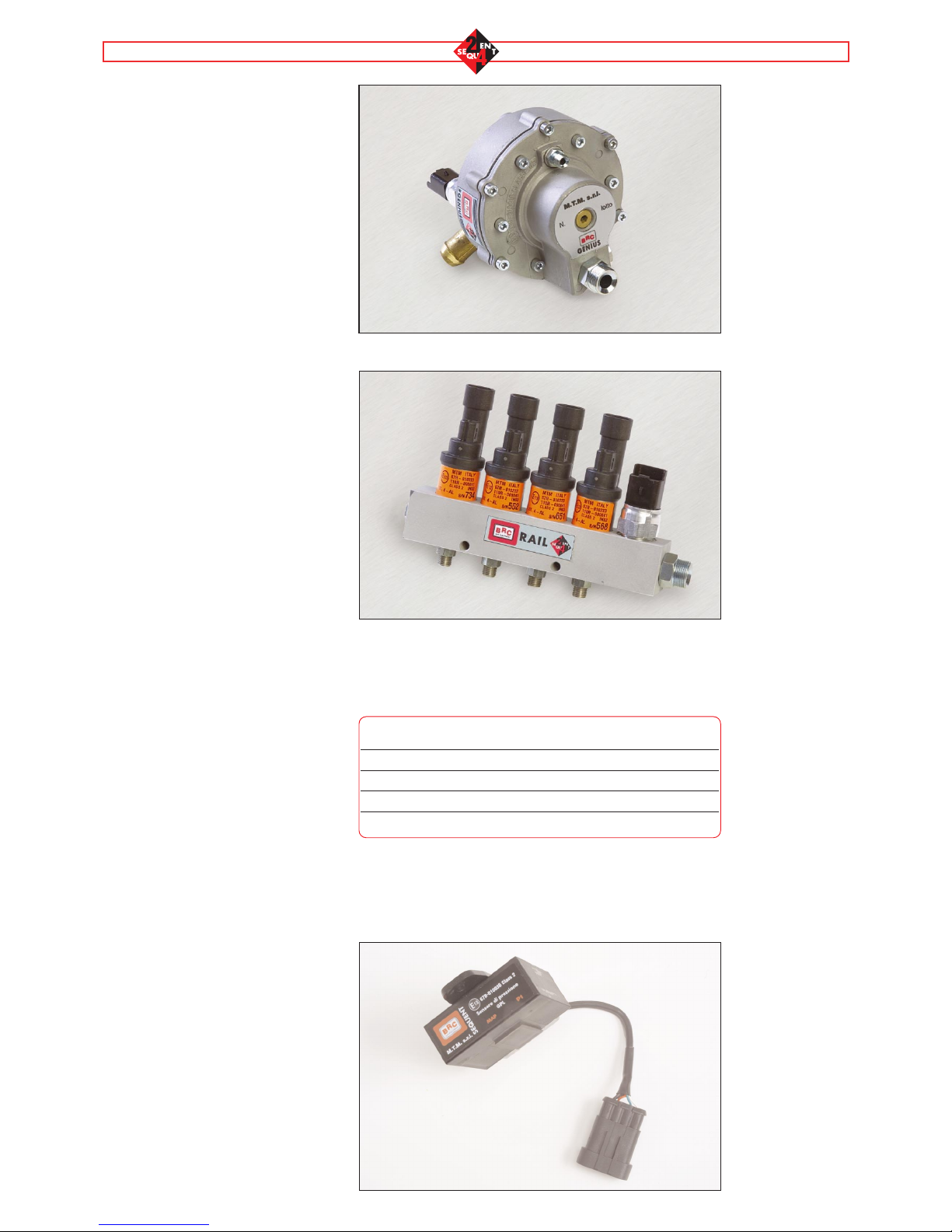
2.5 FUEL “RAIL”
It is the element bearing the injec-
tors fitted. Unlike the previous
sequential systems, the gas pres-
sure and temperature sensor (not
compatible with the previous
systems) is also fitted on the rail in
addition to the injectors (BRC type
only).
2.6 BRC INJECTORS
The SEQUENT 24 equipment only
uses BRC injectors. See in the fol-
lowing table (pitc. 5) the powers, for
guidance.
2.8 GAS PRESSURE AND
TEMPERATURE SENSOR
This sensor is absolutely new, in a
compact body and already integra-
ted with the connector; it contains
the P1 gas pressure and tempera-
ture sensor. The sensor is directly
fitted on the fuel rail. In this position
the measurement of gas pressure
and temperature is more careful
and allows rectifying the gas mixtu-
res more rapidly.
MAP SENSOR
The MAP sensor is identical with
the MAP sensor of the Standard
SEQUENT, already familiar to the
BRC installer. The material differen-
ce distinguishing it from the other
systems is that in the SEQUENT 24
this sensor is used ONLY DURING
THE SELF-MAPPING. During the
Pict. 3
Genius for
SEQUENT 24 and
engine water tem-
perature sensor
Pict. 4
Rail and Gas pres-
sure and tempera-
ture sensor
Pict. 6
MAP sensor
Pict. 5
LPG powers
LPG powers
Genius 800 Genius 1200 Genius 1500
Injectors Max Type Inducted - 26 kW/cyl. 30 kW/cyl.
Supercharged - 32 kW/cyl. 36 kW/cyl.
Iniettori Normal Type Inducted 17 kW/cyl. 21 kW/cyl. -
Supercharged 22 kW/cyl. 26 kW/cyl. -

6
vehicle’s normal operation, the
MAP is estimated: an approximate
value of the manifold pressure is
therefore visualised on the
SEQUENT 24 interface.
For the self-MAPPING the MAP
sensor is provided with the pipes
necessary for the connection on the
vehicle, inside the SEQUENT 24
CALIBRATION KIT Code
09SQ10990001.
2.9 HARNESS
The SEQUENT 24 harness is slen-
derer than the previous systems’
ones. The 56-pole connector har-
ness of the Standard SEQUENT is
replaced by the 24-pole connector
harness of the SEQUENT 24. To
make installation easier the main
devices of the system are connec-
ted through a specific connector
and the quantity of wires to weld is
very small.
Shielded conductors have been
used in order to comply with the
EMC standards. The connectors on
the harness are waterproof with the
exception of the connector of the
changeover switch that is however
housed in the passenger’s com-
partment and is therefore protected
from water. The injectors ought to
be cut with great care: the injectors
cut is the main novelty of the whole
system and of the harness.
2.9.1 INJECTORS CUT
Unlike the previous systems, the
injectors are cut on the positive:
this allows having less wires ente-
ring the ECU.
Two wires are actually enough to
cut all the injectors: the
White/Green wire (injectors positi-
ve, original equipment side) and the
White/Brown wire (injectors positi-
ve, injectors side).
On the other hand, it won’t be pos-
sible to change over from petrol to
gas and vice versa injector by injec-
tor; the changing over could possi-
bly be abrupt and we might change
over only while decelerating on
some vehicles.
The White/Green wire has also the
key contact positive function, i.e. it
is the wire that turns the gas ECU
ON. It is proper to bear in mind, in
this connection, that some vehicles
do not actuate the injectors positive
until the starting up: it is not the-
refore sufficient to turn the key con-
tact on. In this case, the only way to
turn the gas ECU on is to start up.
As while programming, the gas
ECU needs this wire to be high-
potential, programming will be car-
ried out with the vehicle running.
The injectors positive normally is
not low-potential as soon as the
engine and the key contact are
switched off, but it can remain high
for some seconds with the vehicle
switched off. In this case, the ECU
too will remain ON for some
seconds.
The White/Brown wire is directly
connected with the petrol injectors.
It supplies tension on the injectors
positive while running on petrol,
whereas it takes this power supply
off while running on gas, in order to
cut injectors.
It is highly recommended to use
right and left harnesses specifically
conceived for Sequent 24 whene-
ver it is possible. They actually
allow making quick connections
with the injectors, without welding
and cutting down any error possibi-
lity.
It is necessary not to mix up the
right with the left harnesses and to
carefully follow the instructions sup-
plied with these harnesses.
The exchange of the two harnesses
brings about the vehicle’s malfunc-
tion both on petrol and on gas and
the short-circuit of the injectors pilo-
ting outputs of the petrol ECU to
the positive. This short-circuit
strains the petrol ECU only when
the engine is running (it is anyway
not possible to start up).
Furthermore, the petrol ECU is
generally protected against this
type of short circuit. Nonetheless it
is recommended to act very cau-
tiously. In particular, it is recom-
mended not to insist excessively if
the vehicle does not start up after
reconnecting the injectors, but to
check immediately whether the
connection harness is correct.
Should the right and left harnesses
not be used, it is anyway possible
to use the universal harness, fol-
lowing the enclosed instructions
with the utmost care.
In particular, bear in mind that:
- The White/Green wire can be
generally connected only with a
positive wire coming from the petrol
original harness, even if it is best, in
general, to reunify all the positives
of the injectors (ECU side) on this
wire, in order not to supply overcur-
rent to one single wire of the petrol
original harness.
- All the positives of the petrol injec-
tors ought to be cut, by disconnec-
ting them from the original positive
and connected only with the
White/Brown wire. Indeed, should
the original positive still get to a
petrol injector, the injector will also
work while running on gas and the-
refore provoke the bad combustion
of the attendant cylinder.
- The petrol injectors positive to be
cut ought to be as close as possible
to the petrol injectors. If we cut the
positive far from the petrol injectors,
we actually run the risk of cutting, in
addition to the injectors, other
actuators or sensors of the vehicle
supplied with the same wire of the
original equipment.
- The injectors negatives ought to
be cut and connected, as in the
past, to the violet (petrol ECU side)
and orange (injectors side) wires
and ought to be connected in the
same order, from 1 to 4, as the gas
injectors.
At the end of this handbook (Annex

7
B on page 14) you will find an
explanatory diagram regarding the
injectors cut.
The petrol injectors are emulated
through special coils similar to the
coils used in the Modular LD of the
Sequent systems that are fitted
inside the ECU.
The codes of the connection har-
nesses for the 4 petrol injectors
are listed below:
06LB50010121 – UNIVERSAL Harness
06LB50010122 – RIGHT Harness
06LB50010123 – LEFT Harness
3 PROGRAMMING
The software structure is maintai-
ned as similar as possible to the
BRC sequential systems already on
the market and familiar to the BRC
installer. Only the material differen-
ces introduced for SEQUENT 24
will be therefore here-after indica-
ted.
3.1 FILE TYPES
The SEQUENT 24 ECU is pro-
grammed by downloading two diffe-
rent types of files:
1. File .S19
2. File .FSL
the information necessary for the
vehicle’s operation is contained in
the file. FSL.
3.2 ASSISTED PERSONALI-
SED PROCEDURE
Let’s find out, in brief, about the
assisted personalised programming
procedure. The procedure is to be
carried out with the engine swit-
ched on and the changeover switch
on petrol mode (the programme will
show the installer when changing
over to gas).
The steps to follow are not far
removed from the ones analysed
for the Standard SEQUENT and for
the SEQUENT FAST, that’s why
you are kindly requested to refer to
the attendant handbooks for a more
detailed description.
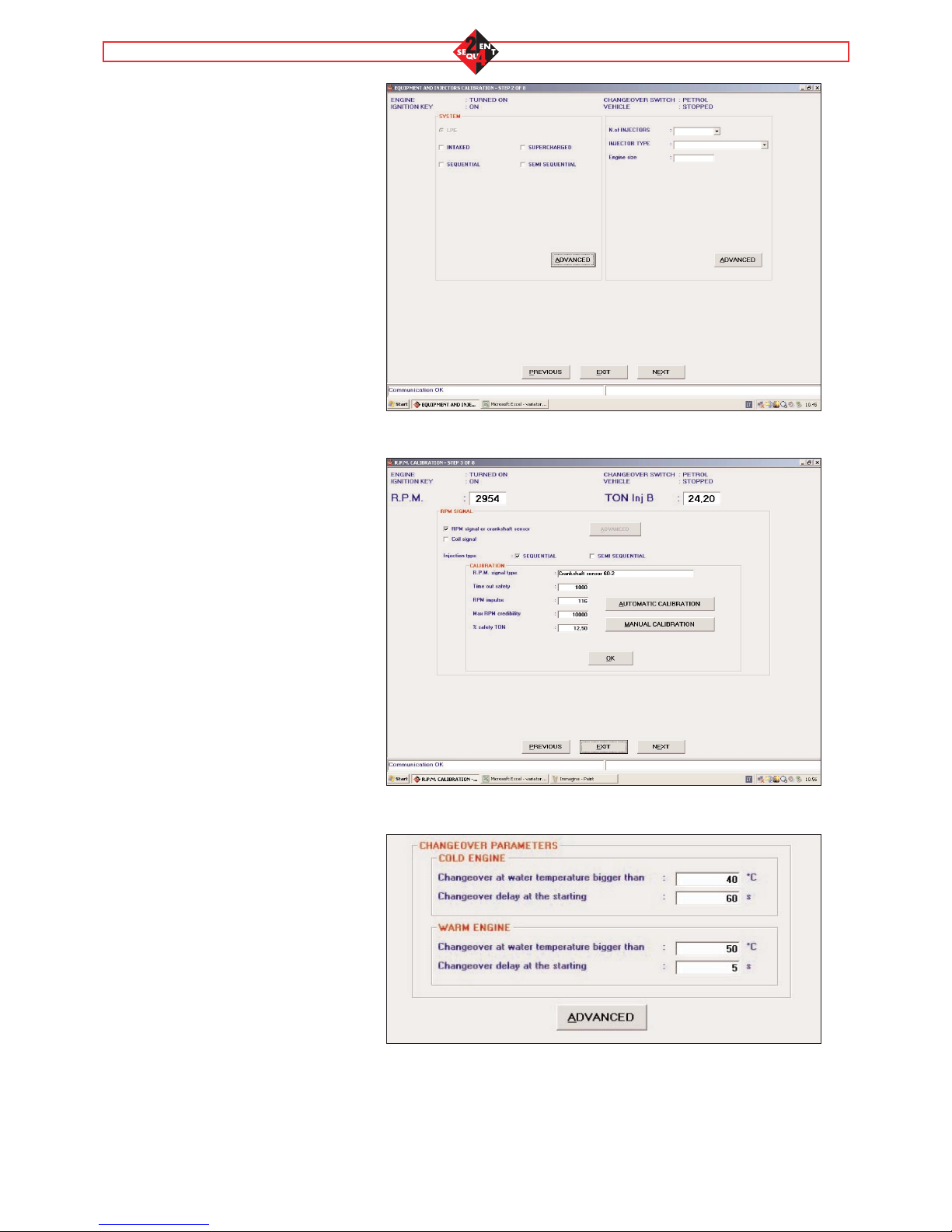
Assisted personalised procedure
The main novelties have been
introduced in the equipment type
screen and in the RPM calibration
screen.
The equipment type screen (Picture
8 pag. 8) requires to enter an extra
information: the vehicle volume.
The RPM calibration screen
(Picture 9 pag. 8) allows selecting a
coil RPM signal besides selecting
and calibrating a normal RPM
signal or crankshaft position sen-
sor.
WARNING: by selecting an
RPM signal from the negati-
ve coil, the RPM won’t be correctly
visualised in all the working condi-
tions. In some of them as, for
example, in the cut-off, the visuali-
sed RPM signal could not corre-
spond to the vehicle’s real one;
nevertheless it doesn’t affect the
vehicle’s working.
4 TUNE-UP
This chapter will only examine the
differences with the previous
SEQUENT systems, otherwise you
are kindly requested to make refe-
rence to the handbooks on the
Standard SEQUENT and
SEQUENT FAST.
4.1 CHANGING OVER
The changing over operation has
substantial differences distingui-
shing it from the previous Sequent
software, owing to the completely
different injectors cut on Sequent
Beginning of the
procedure
Step 1
Step 2
Step 3
Step 4
Step 5
Step 6
Step 7
Selection of the equipment
and injectors type
RPM calibration
Lambda calibration
(optional)
Save file
Self-mapping
Save file
End of the procedure
ASSISTED PERSONALISED PROCEDURE
Pict. 7
8
Pict. 10
24. In particular, the injectors are
simultaneously cut and changeover
can be rough while in the Standard
Sequent or Sequent Fast it was
clean in all conditions. In these
cases it is proper to avoid changing
over in the most critical conditions
that normally are idle speed or con-
ditions requiring much torque to the
engine.
It is obvious from the first screen
(Picture 10) that changing over is
always a function of the engine
water temperature measured throu-
gh the special sensor positioned on
the Genius Reducer for Sequent
24.
On Standard Sequent and Sequent
Fast the changing over temperature
was the gas one unless you con-
nect to the vehicle’s original engine
water temperature sensor.
As a rule, the changing over is divi-
ded into two sections according as
you change over with the warm
vehicle (temperature higher than
50°C) or the cool vehicle (tempera-
ture higher than 40°C).
In the referred example the chan-
ging over conditions are attained if:
1. 60 seconds at least have passed
after the vehicle starting up and gas
temperature ranges from 40° and
50°C.
2. 5 seconds at least have passed
after the vehicle starting up and gas
temperature is higher than 50°C.
By clicking on the ADVANCED but-
ton it is possible to set some para-
meters affecting changing over or
changing back to petrol for lack of
fuel.
In particular, it is possible to distin-
guish the conditions for changing
over from petrol to gas (Box 1 of
Pict. 11) from the conditions for
changing over from gas to petrol
(Box 2 of Pict. 11).
In particular, the following configu-
rations are possible:
- “Changing over at the idle speed”
Pict. 8
Pict. 9
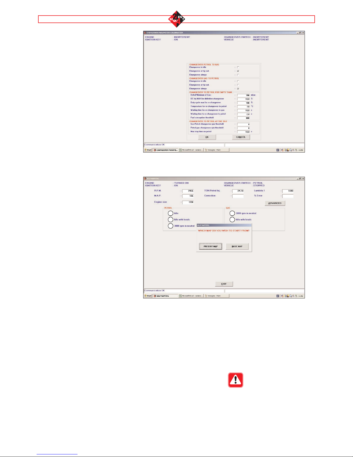
9
indicates that changing over can be
possible at RPM lower than 4000
and with a MAP value close to the
idle speed one.
-“Changing over in deceleration”
indicates that changing over can be
possible in deceleration conditions,
that is to say with RPM ranging
between 2000 and 4000 and a
MAP value close to the idle speed
one. In these conditions the torque
required to the engine is practically
null; this obviously allows avoiding
jerks during this phase. (This chan-
ging over is very similar to the
Flying Injection system). Changing
over in deceleration is suitable for
vehicles whose OBD detects miss-
fires. On these vehicles, petrol-gas
changing over and gas-petrol chan-
ging back are particularly delicate
and they are therefore recommen-
ded only in deceleration conditions.
(NOTE: the manual action on the
changeover switch has anyway
priority on the software; by forcing
the changeover switch on its petrol
mode the gas-petrol changing over
is therefore immediate even if the
changing over in deceleration is
configured in the software).
-“Always changing over” indicates
that changing over is possible in all
conditions and therefore at any
RPM and engine load values.
The standard configurations are:
-Petrol-Gas changing over (Box 1
of Pict. 11): changing over in dece-
leration
-Gas-Petrol changing over (Box 2
of Pict. 11): always changing over
In the “Changing back to petrol for
lack of gas” Box there are all the
parameters controlling this function.
They are the same parameters
already seen for the Standard
Sequent and Sequent FAST. Every
time a new mapping is created,
some given values are already con-
figured; normally they do not need
any modification.
Pict. 11
Pict. 12
The “Changing back to petrol at the
idle speed” Box allows changing
back to petrol every time the engine
is below certain revs; this function
is identical with the Sequent one
and is only used on vehicles whose
return to idle speed is so critical
that it can provoke the engine stall
as a consequence.
4.2 SELF-MAPPING
The self-mapping can be carried
out from the tune-up function too.
The procedure is the same as the
assisted personalised one. The
only novelty is the initial question
(Pict. 12) asking the installer to
decide whether self-mapping from
the CURRENT MAP, that is the one
already existing in the ECU or from
the BASIC MAP, that is by using
the standard maps existing on the
PC. WARNING: It is necessary to
connect the manifold pressu-
re.

5 UTILITIES
This chapter will only examine the
differences with the previous
SEQUENT systems, otherwise you
are kindly requested to make refe-
rence to the handbooks on the
Standard SEQUENT and
SEQUENT FAST.
5.1 INFORMATION
This section allows controlling the
updating of the software versions
existing on the PC that can be
downloaded on the ECU, visuali-
sing the software name and version
(Picture 13).
10
Pict. 13

11
6 PROBLEMS AND SOLUTIONS
This chapter supplies some useful indications for the installer to solve some problems that could arise with this
new system.
The ECU does not communicate
• Lack of power supply to the ECU
• The communication port configured on
the PC is not correct
• The communication cable is faulty
• Turn the engine on
• Verify whether the configured COM port
is correct in UTILITIES-COMMUNICA-
TION
• Replace the communication cable
The ECU does not switch off • The communication with the PC is still
active
• Disconnect the communication cable or
exit from the SEQUENT 24 programme
and wait till the ECU is switched off
The changeover switch does not visua-
lise the GAS level
• The changeover switch is in its petrol
position (level LEDs are switched off)
• The changeover switch does not commu-
nicate (level central LEDs are blinking)
• Changeover to gas and verify the level
visualisation.
• Verify the changeover switch harness or
replace the changeover switch. In these
cases, the cause could also be the ECU.
Therefore verify whether the ECU com-
municates with the PC interface and, if
necessary, try to replace it.
The changeover switch does not com-
municate • The level green central LEDs and the
orange rectangular LED are blinking
• In this condition the vehicle goes on run-
ning on petrol or on gas according to the
changeover switch position. Nevertheless
there is no information on the operation
and it is therefore proper to verify the har-
ness or replace the changeover switch.
The changeover switch does not switch
on
• The changeover switch harness is cut off
• The 5Afuse is cut off
• The changeover switch fails
• The ECU does not switch on
• Verify the changeover switch harness
continuity.
• Replace the 5A fuse
• Replace the changeover switch.
• Verify the ECU operation.
The vehicle works wrongly on gas • The injectors positives are not cut correc-
tly
• Make sure you have cut all the petrol
injectors positives
• Verify you have cut as close as possible
to the injectors.
The Petrol and GAS injectors do not
inject simultaneously (you will find it
hard to make the self-mapping)
• The injectors positives are not cut correc-
tly
• Try to start the vehicle up with the gas
injectors disconnected: if the vehicle
starts up (even running bad) then there is
a problem in the injectors positive cut.
The vehicle does not start up • Inversion between RIGHT and LEFT har-
ness
• Verify whether the injectors are connected
correctly. If the RIGHT harness and the LEFT
harness are inverted, trying to start up, the
tension on the White/Green wire is still low.
The vehicle does not change over to
gas.
• The injectors are not driven to the
ground.
•The battery bond fails.
• Verify the connection of the B1 Pin
injectors ground wire.
• Verify the connection of the C8 Pin bat-
tery ground wire.
The ECU does not switch on or it resets
itself in the gas operation
• The connection to the battery positive is
lacking or is cut off.
• The connection to the injectors positive is
lacking or is cut off.
• Verify the connection of the A1 Pin bat-
tery positive wire.
• Verify the connection of the A7 Pin
injectors positive wire.
WHAT’S HAPPENED? WHAT TO DO
PROBLEM
The vehicle changes over to petrol in
cut-off.
• The RPM signal is taken from the coil
negative. This signal is set to zero in cut-
off.
• Take an RPM signal different from the
coils one.
The vehicle stalls while changing over
to gas.
• The 15Afuse is cut off.
• Any of the actuators relay wires is
disconnected.
• The relay fails.
• The White/Green wire is inverted with the
White/Brown one (in this case you will
hear the relay ringing).
• Verify the 15Afuse.
• Verify the connections on the actuators
relay.
• Replace the relay.
• Verify the connection of the
White/Green and White/ Brown wires.

12
1 2 3 4 5 6 7 8
A+VBATT INJ1- GAS INJ2- GAS INJ3- GAS INJ4- GAS COMINJPET-OUT COMINJPET-IN RPM-IN
BGND-INJ INJ1PET-IN INJ2PET-IN INJ3PET-IN INJ4PET-IN LAMBDA-AIN MAP-AIN P1-AIN
CGAS SV WATER TEMP. K-LINE SWITCH-LINE SENSPOWER LAMBDA-AOUT TGAS-AIN GNDBATT
ANNEXES A
Pins
ANNEXES B
Location of the ECU pins
N. PIN OF
THE ECU
N. PIN OF THE
REMOTE
CONNECTOR
WIRE COLOUR WIRE NAME DESCRIPTION
A1 Note 1 Red +VBATT ECU power supply from battery /
injectors current blow-by
B1 Ring Black GND-INJ Gas injectors ground
C1 1 Green/Black EVGAS Solenoid valve piloting outlet
A2 1 White/Green INJ1-GAS Gas injector 1 piloting outlet
B2 B1 Violet INJ1BENZ-IN Petrol injector 1 inlet
C2 2 Yellow TEMP.ACQUA Water temperature
A3 1 White/Green INJ2-GAS Gas injector 2 piloting outlet
B3 B2 Violet INJ2BENZ-IN Petrol injector 2 piloting intlet
C3 4 White LINEA-K K line diagnostic
serial communication
A4 1 White/Green INJ3-GAS Gas injector 3 piloting outlet
B4 C1 Violet INJ3BENZ-IN Petrol injector 3 piloting intlet
C4 2 Green SWITCH LINE Changeover switch
serial communication
A5 1 White/Green INJ4-GAS Gas injector 4 piloting outlet
B5 C5 Violet INJ4BENZ-IN Petrol injector 4 piloting intlet
C5 Note 2 Red SENSPOWER 5V power supply for sensors and
changeover switch
A6 A2 White/Brown COMINJPET-OUT Petrol injectors common positive,
injectors side
B6 - Yellow LAMBDA-AIN Lambda oxygen sensor analog inlet
C6 Light blue LAMBDA-AOUT Lambda oxygen sensor analog outlet
A7 A1 White/Green COMINJPET-IN Petrol injectors common positive,
petrol ECU side (or +V key)
B7 4 White MAP-AIN MAP analog inlet
C7 4 White TGAS-AIN Temperature analog inlet
A8 - Grey RPM-IN RPM inlet
B8 2 Green P1-AIN Gas pressure analog inlet
C8 Note 3 Black GNDBATT ECU and sensors ground
Note 1: The A1 pin of the ECU (battery positive) is connected with the pin 3 of the connector for the communication with the
PC.
Note 2: The C5 pin of the ECU (sensors positive) is connected with the following pins of the remote connectors:
• Pin 3 of the gas pressure and temperature sensor
• Pin 4 of the changeover switch
• Pin 2 of the MAP sensor
Note 3: The C8 pin of the ECU (ECU and sensors ground) is connected with the following pins of the remote connectors:
• Pin 1 of the gas pressure and temperature sensor
• Pin 3 of the changeover switch
• Pin 1 of the MAP sensor
• Pin 1 of the engine coolant temperature sensor
• Pin 1 of the gas level sensor
13
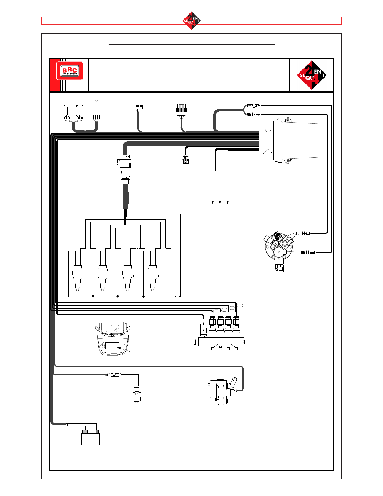
LPG SEQUENT 24
WIRING DIAGRAM
+-
1 2 3 4
1 2 3 4
123
Relé
"I1" "I2" "I3" "I4"
(-) (+)
Sequent 24
ECU
✂
✂
✂
✂
Positive
Negative Orange
Violet
Positive
Negative
Positive
Negative
Positive
Negative
✂White/Brown
White/Green
To connect during is made
of mapping of the car
Caution:
- Follow carefully the petrol injectors sequence and gas injectors as indicated in the diagram.
- Never connect to the earth the front and back solenoid valve wires.
- To allow a correct diagnosis of the front solenoid valve and the back one never connect them together.
- Never substitute the fuses with others of superior carrying capacity.
Battery
Black
Black
Red
Red
LPG
Solenoid Valve
Water temperature
sensor
"GENIUS SEQUENT 24"
Reducer
Petrol
injectors
sequence
Gas
inlet
GAS injectors sequence
Gas temperature
sensor and gas
pressure sensor
1st Petrol
Inject. 2nd Petrol
Inject. 3rd Petrol
Inject. 4th Petrol
Inject.
Orange
Violet
Orange
Violet
Orange
Violet
Orange
Violet
Europa
Multivalve
Lambda Oxygen sensor Light Blue
Grey
Yellow
Level Sensor
Connector
Back Solenoid
Valve Connector
Fuse
5A Fuse
15A Diagnostic
Point
c/o switch
connector
rpm Signal
ANNEXES C
General electrical diagram
14
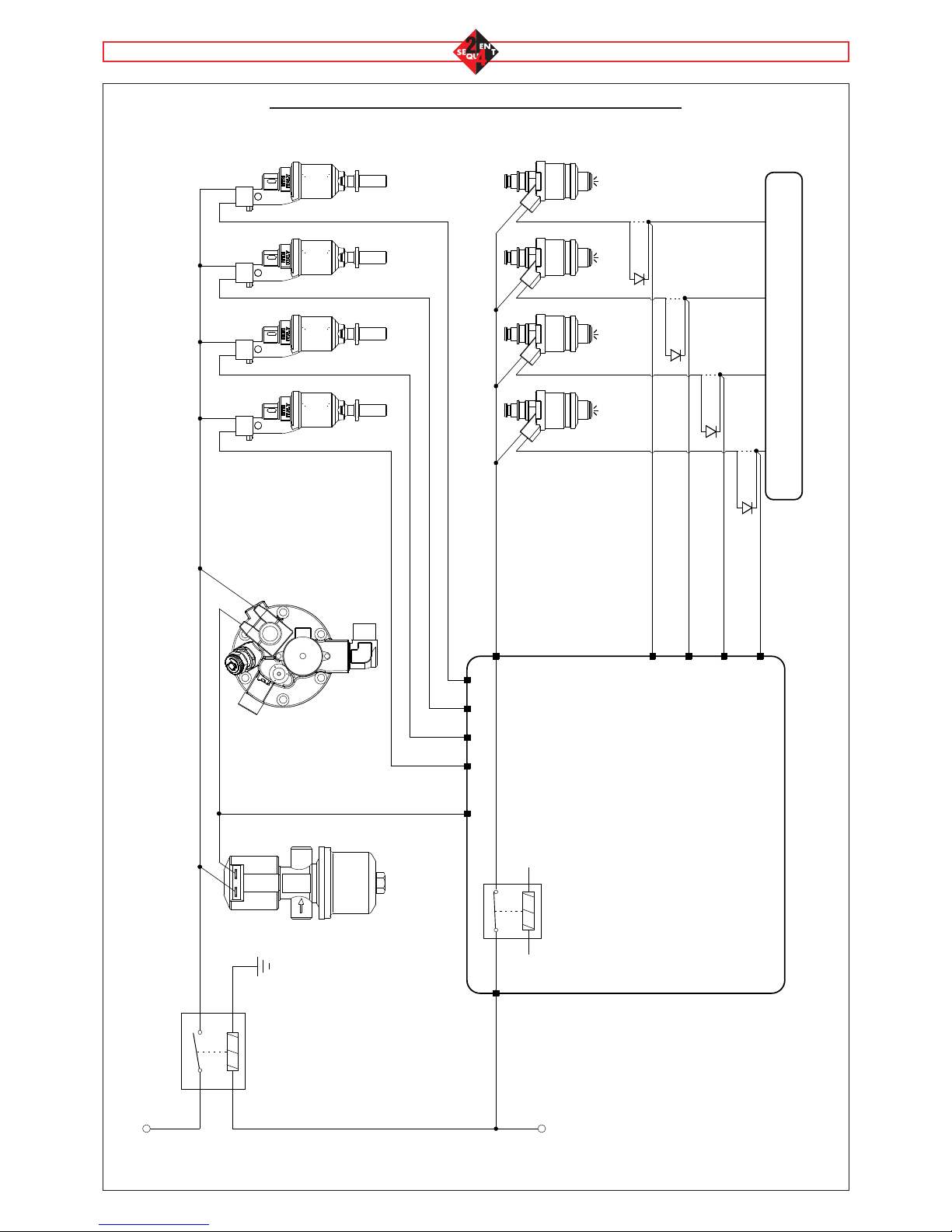
✂
✂
✂
✂
Violet
Orange
Violet
Orange
Violet
Orange
Violet
Orange
Violet
Violet
Violet
Violet
Ex
Ex
Ex
Ex
ITALY
M.T.M.
ET 98
White/Brown
Gas 1st
Injector Gas 2nd
Injector Gas 4th
Injector
Gas 3rd
Injector
A6
B5
B4
B3
B2 PETROL ECU
A5
White/Green
A4A3A2
White/Green
White/Green
White/Green
LPG
Solenoid Valve
SEQUENT 24
ECU
External Relé on the
wiring Sequent 24
Positive Petrol
Injector
C1
A7
White/Green
Grenn/Black
Ground
+12V After Contact
Europa
Multivalve
1st Petrol
Inject. 2nd Petrol
Inject. 3rd Petrol
Inject. 4th Petrol
Inject.
ANNEXES D
Injectors cut diagram
15
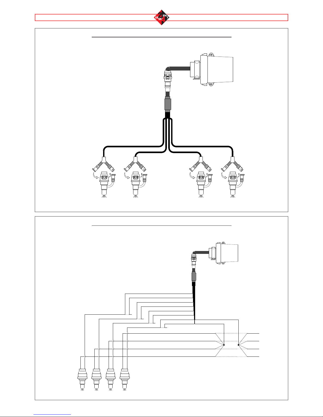
✂
✂
✂
✂
✂
✂
✂
✂
ANNEXES E
4-Petrol injector connection Sequent 24 Harness Right or Left
ANNEXES F
Universal 4-Petrol injector connection Sequent 24 Harness
Sequent 24
1° Injector 2° Injector 3° Injector 4° Injector
Negative
Positive
Violet
Orange
Violet
Orange
Violet
Orange
Violet
Orange
Inj. 1 Petr.
Inj. 1 Petr.
Inj. 2 Petr.
Inj. 2 Petr.
Inj. 4 Petr.
Inj. 4 Petr.
Inj. 3 Petr.
Inj. 3 Petr. White/Green
White/Brown
SEQUENT 24
1°
Injector 2°
Injector 3°
Injector 4°
Injector
Table of contents
Popular Power Tools manuals by other brands

Rikon Power Tools
Rikon Power Tools 80-805 Operator's manual

Makita
Makita 6917FD instruction manual

Gude
Gude WP 12 T Translation of the original instructions

Makita
Makita DST112ZJ instruction manual

Torin BIG RED
Torin BIG RED T51201 owner's manual

Drill Master
Drill Master 120 Volt Variable Speed Jigsaw manual


