Breezair IWC05 User manual

®
Application
Notes
Application
Notes
Industrial Wall
Control (IWC05)

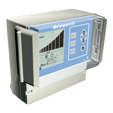
The Breezair Industrial Wall Control (IWC05) is designed to provide both local and external Evaporative Air cooler
control for all Breezair air coolers fitted with the CPMD digital module. The external control may be either a PLC or
Building Management System. The IWC05 is designed to accept external input voltages ranging from 4VDC to
32VDC and will switch outputs ranging from 1.4VDC to 32VDC at a load of 40mA. The IWC05 has binary outputs
for Temperature and Humidity for use with other equipment.
CABLE LENGTHS
The maximum total cable length between the cooler CPMD module and the Remote sensor (via the IWC05)
is 100m. Within this limit, the maximum sensor cable length must not exceed 60m. EG: a combination of 40m of
comms (communications) cable and 60m of sensor cable is permitted and 80m of comms cable and 20m of sensor
cable is permitted.
Each IWC05 kit is provided with one 20m sensor cable and one 40m comms cable. 80m comms cables and 60m
sensor cables are available as an option, to be purchased separately.
The above restrictions apply in order to avoid excessive voltage drop and electrical noise.
YOU MAY USE LONGER CABLES WHEN REQUIRED, BUT WHEN YOU DO THE FOLLOWING CONDITIONS
MUST APPLY:
Cable conductors must be larger to reduce voltage drop.
Cables must be screened (or shielded) to reduce noise.
Screens must be earthed (grounded).
Ensure that conductors are correctly orientated. Use junction boxes or high quality plugs for
terminations.
Seeley International takes no responsibility for mal-function of the IWC05 when longer
cables are used.
See diagram 2.
11
Industrial Wall Control Application Notes
11
AUTO [Auto] mode, and manual control of the cooler functions in the MANUAL [Man] mode.
The IWC05 may also be set up to control the Air Cooler from EXTERNAL devices, such as PLCs and Building
Management System computers. In this case the IWC05 will cease to function in its AUTO [Auto] or MANUAL
[Man] mode and will respond only to the external commands.
The IWC05 provides at all times outputs that may be employed to command other external devices such as
dampers, fans, signal equipment, etc. These outputs contain the status of the various Air Cooler components (fan,
pump, drain valve), as well as the Remote Sensor temperature and humidity values.
To ensure signal integrity over distances greater than 100 meters between the IWC05 and the PLC or Building
management system it is advisable to use shielded cables.
INPUT CONFIGURATION
Connect the Positive input to the input terminals. This voltage must range between 4VDC to a maximum of 32VDC.
Current in the input is limited by the series resistors.
Connect the Negative input to the common terminal.
All inputs to the IWC05 are optically isolated from the main circuits.
The IWC05 does not have its own internal power supply to operate the external inputs.
These cables are transmitting digital signals
and must not be installed next to power cables.
INPUTS AND OUTPUTS
The IWC05 may be set up to control the Air Cooler
as a local machine, independent of any other
devices. In that case there will not be any
connections made to the Input and Output
terminals. The Remote Sensor supplied in this Kit
together with the IWC05 will provide automatic
temperature and/or humidity control along with its
water management and auto drain features in the
WHITE WHITE
WHITE
WHITE
BLACK BLACK
BLACK
BLACK
RED RED
RED
RED
GREEN GREEN
GREEN
GREEN
YELLOW YELLOW
YELLOW
YELLOW
BLUE
ILL1415-A
BLUE
BLUE
BLUE
2
CONNECTION ORDER FOR SENSOR CABLE ONLY

3
J4
IN1
IN2
In3
IN4
COM
ILL1345-A
Industrial Wall Control Application Notes
INPUT CONFIGURATION (continued)
In EXTERNAL [EXTERNAL] mode the power source must be
provided adjacent to the Wall Control via a power outlet and
adaptor. The adaptor may be a common small appliance adaptor
such as used for telephones, answering machines, weigh scales
etc, having the specified electrical output (see page 1).
INPUTS
If any one of inputs 2,3 or 4 is high, the IWC05 MANUAL [Man]
and AUTO [Auto] controls will be over-ridden and the IWC05 will
not respond to temperature and humidity changes sensed by the
Remote Sensor. In EXTERNAL [EXTERNAL] andAUTO [Auto]
modes the Temperature and Humidity and clock displays will cycle
every 5 seconds.
Input 1 [Power] - Remote OFF
This input enables the Cooler to be switched OFF.A positive voltage to the input 1 of the IWC05 holds the system
in the OFF state, and is indicated on the IWC05 screen by a R.
WARNING! It is not recommended that this switched input be used to control the Cooler in an emergency
situation, because it is not fail-safe, ie: if for any reason the cable continuity is cut, it is not possible to
apply a positive voltage to input 1 to switch the cooler OFF.
Input 2 [F1] - Fan1
This input enables the fan to run at minimum speed when a positive voltage is
applied. It functions in conjunction with Input 3 in a binary code to provide
the external control with three different speed settings for the cooler fan. With
Input Fan1 and Fan2 positive the cooler will run at maximum speed.
Input 3 [F2] - Fan2
This input enables the fan to run at medium speed when a positive voltage is applied when there is no voltage on
Input 2. With Input Fan1 and Fan2 positive the cooler will run at maximum speed.
Input 4 [Pump] - Pump ON / OFF
This input enables the pump to run when a positive voltage is applied. However, the pump operation is subject to
the CPMD module and the status of the cooler. If there is insufficient water in the tank the pump will not run until
water is at the correct level as sensed by the water probes.
Input 5 [H.E.] - Humidity Enable
This input only functions when the IWC05 is in EXTERNAL [EXTERNAL] Mode. It is possible for External controls
to drive the cooler to the point where the room humidity exceeds the default set point as sensed at all times by the
Breezair Remote Sensor. This input enables the IWC05 to over-ride the external pump command and disallow the
pump to run when the room humidity goes high. If this Input is not enabled, the pump will run as required by the
external command regardless of room humidity.
Input 6 [DT] - Pad Dry Time
In AUTO TIMER mode only, when the clock stops the cooler, the fan will continue to run for 60 minutes on speed 2
in order to dry the cooling pads.
Input 7 [HD] - Humidity Disable
This input disables Humidity control in AUTO [Auto] mode when no External [EXTERNAL] control is present. The
case may arise in AUTO [Auto] in which the temperature is satisfied and the fan is therefore stopped. BUT the
indoor humidity may fall below the set point and the IWC05 will demand that the cooler operate to raise the
humidity to the set point. The effect will be to lower the room temperature still further. If this is undesirable, the
humidity control may be disabled by this input.
Input 8 [Sp1] - Spare
Currently there is no requirement for this input.
22
FAN
XX
XX
XX
XX
INPUT 2 INPUT 3
OFF
HIGH NIL NILHIGH
LOW
MED
HIGH

Output 2 [Fan] - Fan ON / OFF
This output is activated whenever the air cooler fan has been turned ON.
Output 3 [Pump] - Pump ON / OFF
This output is activated whenever the air cooler pump has been turned ON.
Output 4 [Ext] - External Control
This output is activated whenever the air cooler is under external control.
Output 5 [Fault] - Fault ON / OFF
This output is activated whenever the air cooler is in a fault condition. Refer to Installation and Operation manual,
SERVICE [SERVICE] Mode, page 8 for more details about faults.
Output 6 [S.Hum] - Serial Humidity
This output is activated whenever the air cooler has been turned ON or is in Standby Mode. The binary information
represents humidity as a percentage. The bit stream is described on page 4.
For example, consider a relative humidity of 32%, the bit stream will be: -
00000000{00100000} Therefore read as 32%RH
32
Output 7 [S.Temp] - Serial Temperature
This output is activated whenever the air cooler has been turned ON or is in Standby Mode. The binary data
represents 10 x Temperature (in °C). The bit stream is described on page 4.
For an example, consider a Temperature of 20.3°C the bit stream will be: -
0000000{011001011} Therefore read as 20.3°C
203
Output 8 [Drain] Drain Control Output
This output is activated whenever the Drain Valve is open. It will activate only after the time delay period set in the
IWC05 Program. The output will remain activated while the Drain valve is open. If the Drain valve opens for a
period of time less than the delay time set, the output signal will remain activated for 5 seconds only.
OUTPUT CONFIGURATION
IWC05 outputs 1,2,3,4,5 & 8 are switches only. They will function when
connected to a power supply from an external source of (1.4 - 32VDC at
40mA load).
Connect the external DC power supply to the load, connect the negative of
the load to the desired output terminal and connect the negative of the
power supply to the common [com] terminal on the IWC05. The output will
then turn on your load as desired (page 4).
Outputs
All outputs are indicators only of the state of the air cooler. None of them
are monitored for integrity. Afault on an output line is not indicated in the
IWC05.
Output 1 [ON] - System ON / OFF
This output is activated whenever the Air Cooler has been turned ON from
any source, in any mode.
Industrial Wall Control Application Notes
4
J6
OUT1
OUT2
OUT3
OUT4
COM
ILL1346-A
33

44
Industrial Wall Control Application Notes
Start pulse
Pause
L HDL HDL
msb DATA lsb
0 0 1 0 1 1 0 0
0 0 0 0 0 0 0 0
msb Zero byte lsb
Pause
Temperature and Humidity bit stream
The IWC05 outputs Humidity and Temperature readings for use with a PLC or building management system.
Humidity is output on terminal OUT6 of J7 and Temperature is output on terminal OUT7 of J7. The Temperature
data word is 9 bits after 7 bits of leading zero's, while the Humidity data byte is 8 bits after a leading zero byte of 8
bits. The temperature value in binary is 10 x the Temperature reading (for example: 20.6°C is sent as a value of
206).
The below example (shown at 1sec/div) is 44%RH which is 00101100 in binary.
The bit format is S L H D L H D L …H D L P where:
S = Start pulse
L = Low
H = High (for synchronisation purposes)
D = Data state (high or low)
P = Pause
The Humidity Bit stream is as follows: The Temperature Bit stream is as follows:
Start Pulse Start Pulse
Bit 15 to Bit 8 all Zero (0) Bit 15 to Bit 9 all Zero (0)
Bit 7 (msb of data) Bit 8 (msb of data)
.. ..
.. ..
Bit 0 (lsb of data) Bit 0 (lsb of data)
Pause Pause
The bit timing is as follows:
Start pulse 750mSec on, 250mSec off
A High Bit 500mSec on, 250mSec off
A Low Bit 250mSec on, 500mSec off
Pause 1000mSec off
Update Rate 14 seconds
Shift in PLC LEFT

ILL 1339-D
Power
Pump
On
Fan
Pump
Ext
J6
J4
OUT
IN
F1
F2
1
2
3
4
5
1
2
3
4
5Com
In1
In2
In3
In4
Com
Out1
Out2
Out3
Out4
S.Hum
S.Temp
OUT
IN
H.E
SP1
Fault
Drain
J7
J5
HD
DT
1
2
3
4
5
1
2
3
4
5
Com
In5
In6
In7
In8
Com
Out5
Out6
Out7
Out8
1
2
3
4
5
All Commonsconnected
to Negative
0VGround
NPN
RJ11RJ12
0VGround
All Commons connected
to Negative
Q2
Common
4-32VDC
<=12mAmps CPMD
COMMS
REMOTE
SENSOR
D2
D1Common
R2
1.4-32VDC
<=40mAmp
D3
Q1
J3
J2
R1
Input
RES-NTC
RL
Output
RL
R3
P/N856315-B
INPUT
CONNECTION
OUTPUT
CONNECTION
(C)SEELEYINTERNATIONAL
AUSTRALIA 2004
4-32VDC
1.4-32VDC
Industrial Wall Control Application Notes
55
5
60m.
CPMD
HUB 1
HUB 2
SENSOR
Industrial Wall
Industrial Wall
Control
Control SENSOR
CPMD
CPMD
CPMD
20m.
Any length
OK up to combined
length of 140m from
IWC to CPMD.
Any length
OK up to combined
length of 200m from
IWC to CPMD.
60m.
CPMD
CPMD
CPMD
CPMD
CPMD
max 40m !
max 40m !
max 40m !
max 40m !
max 40m ! max 40m !
max 40m !
max 120m !
max 120m !
max 140m !
!Coolers are supplied with 20m data cable in
accessories kit
!Hubs are supplied with 20m data cable in kit.
!Industrial Wall Controls (IWC) are supplied with
20m Sensor cable in kit
!60m Sensor cable on reel available
!20m data cable in re-sealable bag available
!40m data cable on reel available
!60m data cable on reel available
!80m data cable on reel available
!100m data cable on reel available
!4-way in-line joiners available to extend data cable
to maximum lengths shown on diagram
!Data cables may be shortened or lengthened (to
maximums shown), using ONLY correct RJ
connectors and crimping tools
!Cables supplied by Breezair are 26AWG, 7/013, 4
core & 6 core flat
!ALWAYS route cables at least 300mm away from
regular power cables and high power machines.
Cross over power cables at right angles.
!Where maximum data cable and sensor cable
lengths are exceeded, or cables are not routed in
accordance with our recommendations Seeley
technical support is not available and the product
warranty may be voided.
Breezair Control System
Cable Lengths
Industrial Wall Control
824130-A 0703
MASTER
MASTER
MASTER
SLAVE 1
SLAVE 1 SLAVE 2
SLAVE 3
SLAVE 3
SLAVE 2
Any length
OK up to combined
length of 200m from
IWC to CPMD.

Industrial Wall Control Application Notes
66
FAN SPEEDS & AIR FLOW
When the wall control is NOT set for EXTERNAL [EXTERNAL] mode, the fan is controlled through 10 speeds
according to the automatic or manual settings.
When the wall control is set for EXTERNAL [EXTERNAL] mode, the fan can only operate at the following 3
speeds:
MINIMUM Speed 3
MEDIUM Speed 6
MAXIMUM Speed 10
For the purpose of applying the Breezair coolers to various downstream systems, the air flow performance curves
are provided below.
Breezair TBA 550 Airflow -Industrial wall control speed settings
for "External" fan speed inputs.
0
20
40
60
80
100
120
140
160
180
200
1000 1100 1200 1300 1400 1500 1600 1700 1800 1900 2000 2100 2200 2300 2400 2500 2600 2700 2800 2900 3000 3100
Airflow L/s
StaticPressure(Pa)
Speed 10 - max
Speed 6
Speed 3
As the policy of this company is one of continuous improvement, all specifications are subject to change without notice.
Seeley International Pty Ltd
1-11 Rothesay Ave St Marys, Adelaide, South Australia 5042

828534-D 0705
ILL1331-A
Table of contents
Other Breezair Controllers manuals
Popular Controllers manuals by other brands

Seada
Seada G2000CTL user manual
GreenWave Reality
GreenWave Reality GL30000 manual

Matsunaga
Matsunaga TSA-1030-CJ operating instructions
Ascon tecnologic
Ascon tecnologic X33H operating instructions
Cisco
Cisco SFS 3504 installation guide

Emerson
Emerson Hytork XL26 Installation, operation & maintenance instructions
