Mounting Location:
Volume controls should be placed in acces-
sible wall locations that are close to entry ways,
exits, light switches, or telephones. They may
also be ganged with other low voltage* controls
such as keypads or infrared repeaters.
*Note:
MUSICAVC-70ZS should not be mounted into
the same electrical box used for a 110 volt de-
vice even if the box says it is partitioned for this
purpose. Speaker wires may pick up electrical
noise which will be transmitted as a buzzing or
popping sound to the loudspeakers.
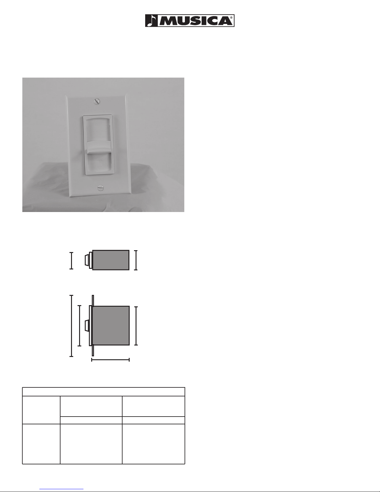
Mounting Requirements:
MUSICAVC-70ZS units require a 18 cu. in.
E.O. Box with a minimum inside depth of 2.620”
and a minimum inside height of 2.550”. Rec-
ommended boxes for new construction include:
Carlon PVC switch box #B118A, and RACO
PVC outlet box. For retrofit applications, Carlon
PVC switch box B120R may be used.
Calculating the proper Impedance settings
for the system:
MUSICAVC-70ZS is an impedance-matching
stereo volume control that allows multiple loud-
speaker pairs and volume controls to be con-
nected, in parallel, without the additional cost
of a separate impedance-matching device. For
flexibility in system design, MUSICAVC-70ZS
has three impedance matching capabilities:
2X, 4X, and 8X as well as a 1X non-impedance
matching setting that allows the unit to be used
as a volume control.
To determine which setting should be used
(1X, 2X, 4X, and 8X) you will need to know the
number of loudspeaker pairs, the loudspeaker
impedance, and the load capability (output im-
pedance) of the amplifier. Most amplifiers will
handle a load down to four or two ohms with
some going as low as 1 ohm.
Using the chart on page one; cross reference
the number of loudspeaker pairs to the amplifier
impedance.
Example:
If you have 8 pairs of 8 ohm loudspeakers and
an amplifier capable of handling a 4 ohm load
you must set the volume control at the 4X setting
for the amplifier to drive all 8 pairs of speakers at
full volume. Note that the 2X setting allows only
4 pairs of 8 ohm loudspeakers to operate on
a 4 ohm load. If however, you could select
an amplifier with a 2 ohm output impedance,
the same 8 loudspeakers could operate on
a 2 ohm load (at the 2X setting) or 16 loud-
speaker pairs (at the 4X setting). Whenever
possible, the lowest switch setting for a given
amplifier should be selected.
Changing Impedance Setting:
Once the proper impedance setting is de-
termined, locate the impedance switch on the
back side of the circuit board. Next, locate
the 1X, 2X, 4X and 8X settings on the circuit
board. If the settings are correct, continue to
the next step. If the settings need to change,
simply slide the switch to the correct setting.
Limitations:
MUSICAVC-70ZS limits the degree of im-
pedance matching to eight times so that
music quality and overall performance is not
sacrificed. We do not recommend that any
quality, multi-room music system be connect-
ed to a device which provides 16X impedance
matching as it may limit the amplifier’s power
and system performance.
Pre wiring and Installation:
A) Mount the outlet box or plaster ring in
the wall (see mounting requirements). Each
room’s wiring can be individually run back to
the amplifier (home run) or connected from
one room to the other (daisy chain). The
daisy chain wiring method connects one set
of speakers with volume control in parallel
to the next, using connection block or crimp
connectors in between. This method has the
advantage of requiring less wiring for the sys-
tem rough-in, but allows for little or no system
upgrading for future applications.
With either method, be sure to mark the
cable connected to the amplifier as (INPUT)
and write down the color codes you have
designated for the left channel, right channel,
positive, and negative leads.
B) If using the “Home Run” wiring method,
each rooms speaker/volume control wiring
should be individually run back to the Main
Equipment Location “MEL” in a “Home Run”
fashion. Run a total of four conductors of
speaker cable from the amplifier location to
each room’s volume control box.
Note:
Many building and fire codes require cable to
be CL-2, CL-3, or FT4 rated. Check with your
local building inspector before pre wiring.
C) Next, run a two-conductor speaker cable
from the outlet box to the corresponding left
and right speakers. Mark each cable (LEFT)
and (RIGHT) and determine the polarity of each
channel (positive and negative).
D) Cut the cable accordingly, allowing enough
cable to hang outside the outlet box, to properly
connect the volume control. Tuck the cable back
into the outlet box to prevent damage during
drywall installation.
E) Tuck the excess cable from inside the outlet
box back out into the wall or fold wires carefully
while inserting the volume control into the outlet
box. Position the volume control so that the front
bracket lines up with the mounting holes on the
box. In some cases the MUSICAVC-70ZS may
be a tight fit requiring it to be inserted on the right
side of the outlet box and then slid left into the
center position.
Note:
In retrofit applications, metal extension plates
and non-recommended outlet boxes may require
field modification to accept the units’ higher and
deeper profile.
Pre-Wiring and Installation
F) Secure unit with supplied silver colored
screws. We recommend tightening the screws
then backing them out 1/4 turn to allow move-
ment side to side and front to back. This will al-
low the face plate to fit flush when the cover plate
is installed.
G) Select the cover plate and screws that
match the knob/trim piece color. Mount the cov-
er plate and fasten with screws.
INSTALLATION
INSTRUCTIONS
FOR
MUSICAVC-70ZS
These diagrams show examples of a sys-
tem that used 8 ohm loudspeakers and
an amplifier capable of handling a 2 ohm
load.
Set each MUSICAVC-70ZS volume control
impedance switch according to the chart
on the front of this sheet.
The wiring depicts how volume controls
can be daisy chained or wired in home run
fashion from each volume control to the
amplifier.
21A8469
1 Mitek Plaza/ Winslow, IL 61089/ 815-367-3000/ 800-225-5689
www.MusicaAtHome.com
Stereo Amplifier / Receiver
capable of handling a 2-ohm load
Connect additional volume controls if de-
sired. Confirm maximum quantity by refer-
encing the impedance chart on front side.
Connect additional volume controls if de-
sired. Confirm maximum quantity by refer-
encing the impedance chart on front side.
*MEL* Main Equipment Location
Connector
Block
Stereo Amplifier / Receiver
capable of handling a 2-ohm load