Breezaire WKS 2200 Series User manual
8610 Production Avenue lSan Diego, California 92121 l(858) 566-7465 lFax (858) 566-1943 lWWW.BREEZAIRE.COM
BREEZAIRE Products Company - 8610 Production Avenue - San Diego, CA USA 92121 - (858) 566-7465
WKS 2200 SERIES
(USA only)
--INSTALLATION INSTRUCTIONS--
Thank you for choosing a BREEZAIRE cooling unit. We believe our products are the best
on the market and will provide many years of trouble free service.
Please take a few minutes and read this entire instruction before beginning the installation.
MODEL_
__
__
__
__
__
__
__
__
__
__
__
__
__
__
__
__
__
__
__
__
__
_SERIAL NUMBER_
__
__
__
__
__
__
__
__
__
__
__
__
__
__
__
__
__
__
__
__
__
_
INSTALLED BY _
__
__
__
__
__
__
__
__
__
__
__
__
__
__
__
__
__
__
__
__
__
__
__
__
__
__
__
__
__
__
_DATE_
__
__
__
__
__
__
__
__
__
__
__
__
__
__
__
__
_
While great effort has been made to provide accurate guidelines, BREEZAIRE cannot warrant its units to properly cool a particular enclosure. Customers are cautioned that enclosure
construction, unit location and many other factors can affect the operation and performance of the unit. Therefore the suitability of the unit for a specific enclosure or application must
be determined by the customer and cannot be warranted by BREEZAIRE.
Before removing the cooling unit from the box, please inspect for damage which might have been
incurred during shipping. If damage is found, notify the Freight Company immediately.
BREEZAIRE is not responsible for any damages incurred during shipping.
WKS 2200 05/06 PG2
INSTALLATION INSTRUCTIONS
FOR WKS 2200 SERIES COOLING UNITS
The BREEZAIRE WK Series cooling units are designed to, when installed in a properly constructed enclosure, provide a
constant, selectable temperature between 48°F and 62°F while reducing the excess relative humidity to the proper 50% to
75%. BREEZAIRE cooling units are designed to lower the temperature, while removing only excessive moisture. In a
properly constructed enclosure this process can raise the relative humidity. The unit does not add moisture to the enclosure.
The unit does not include a heating system and will not warm the enclosure. The WKS Series is not intended to cool service
cabinets, which are maintained at lower temperatures and opened or entered frequently.
The WKS Series cooling unit, is shipped as components, not a working cooling system. Only after a qualified refrigeration
installer has properly connected these components, pressured tested, evacuated, charged with refrigerant and tested their
installation, can the unit be considered a cooling system. Proper installation is critical to the performance, reliability and
longevity of the system. For this reason, BREEZAIRE can only warrant the quality of the WKS components. The
installation and proper operation must be warranted by the installer. Before installation is to begin, the purchaser and
installer should carefully read the enclosed Limited Warranty.
ENCLOSURE CONSTRUCTION
To use the below SIZING GUIDE, the enclosure to be cooled must be built to the following minimum specifications. If the
enclosure is not built to these specifications, consult your BREEZAIRE dealer for assistance in choosing the correct unit.
BREEZAIRE units are not warranted to cool a specific enclosure.
All interior walls and floor should have a vapor barrier and a minimum of R-11 insulation. All exterior wall's insulation values
should be a minimum of R-19. The ceiling should have vapor barrier and a minimum of R-19 insulation. The vapor barrier
should be installed on the warm side of the insulation. There should be no glass windows or doors.
FAll joints, door frames, electrical outlets or switches and any pipes or vents which go through the enclosure should be
sealed to prevent air and moisture leakage into the room. Concrete, rock and brick are not insulation or moisture
barriers.
FDoors into the enclosure should be of minimum size, insulated to R-11 and be tightly sealed with a high quality weather
stripping. Be sure to seal the bottom of the door and the fill gap between the door's frame and wall before installing the
cap molding.
FEnclosure lighting should be of low wattage, with a timer to insure lights are not left on when the enclosure is
unoccupied. Recessed lighting should not be used as they will allow outside air to enter the enclosure.
FThe ambient temperature surrounding the enclosure should not exceed the desired cellar's temperature by more than
25°F. No enclosure wall should receive direct sunlight or strong wind.
FThis is a mechanical piece of equipment, it will make noise and produce heat from the condenser (Figure 2).
Remember, unit installation location is not only important inside the wine cellar, but just as important is where the warm
exhaust air is being rejected.
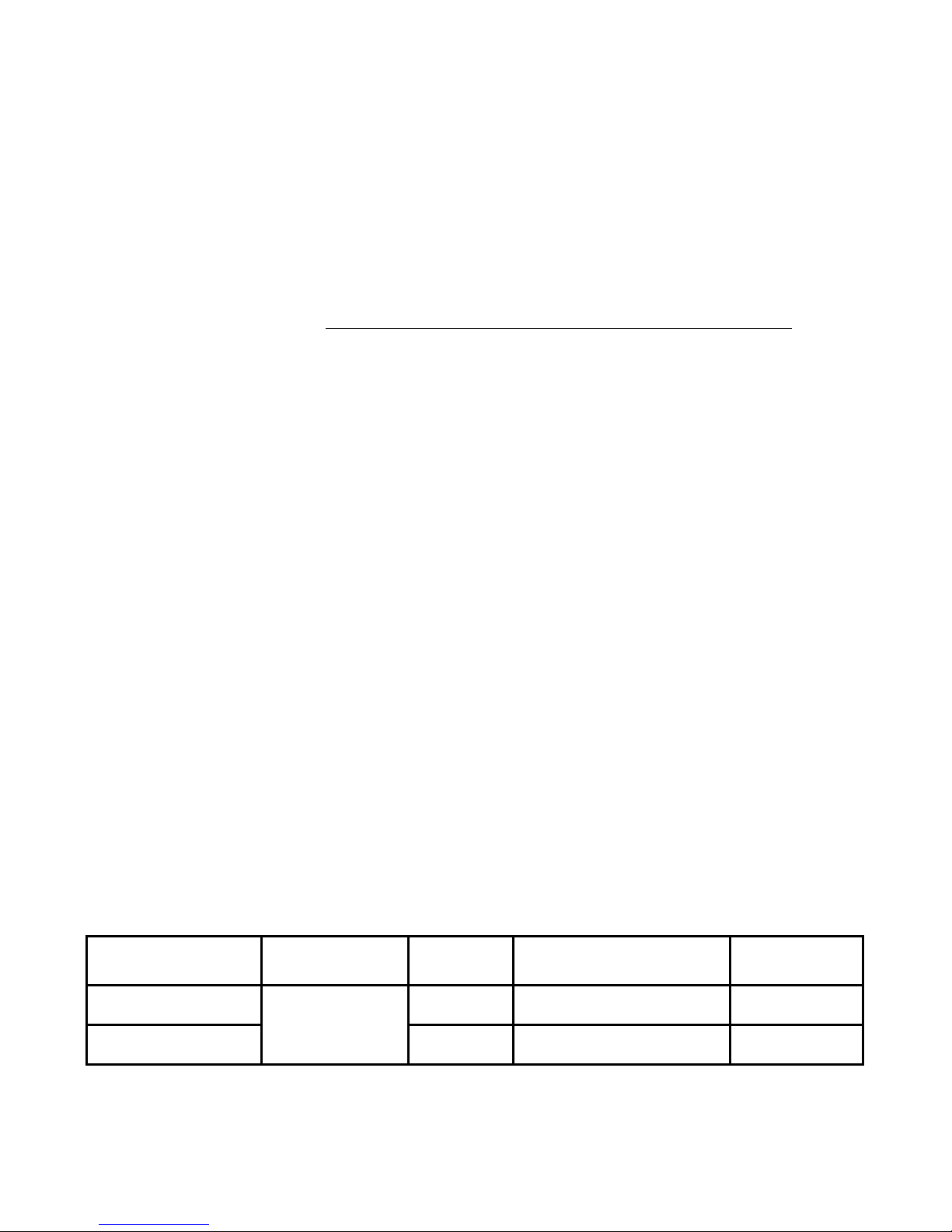
SIZING GUIDE & SPECIFICATIONS
This guide is to be used only for enclosures meeting the above construction requirements.
BREEZAIRE
Model Enclosure
Volume Electrical Dimensions (inches) Weight
WKS 2200 Fan/Coil
(Figure 1) 1 Amps 22w x 11h x 8d 25 lbs
WKS 2200 Condenser
(Figure 2)
265 cu.ft. 4 Amps 14w x 10h x 12d 35 lbs
Note: All units are 115 Volt, 60 Hz

WKS 2200 05/06 PG3
INSTALLATION
BREEZAIRE recommends the use of a licensed refrigeration technician to install the WKS systems. Installation of the
unit's line set through a fire rated wall must be done in accordance with your local building inspector and building codes.
FIf your installation cannot be performed in accordance with these instructions contact your dealer.
FThe unit must be installed in the upright position and are not designed to have duct systems attached to either unit. Do
not drill any holes into the cooling unit. This may damage the unit, promote rust, and will void the warranty.
FBefore installing the unit, inspect it again for any shipping damage. The WKS systems consists of two components,
the condensing unit (Figure 2) and the fan/coil unit (Figure 1). The condensing unit includes the compressor,
condenser coil, fan assembly, sight glass and two service ports. The fan/coil unit includes an internal, adjustable
thermostat (48° to 62°F), capillary tube, filter drier, evaporator coil, and fan assembly.
FMounting the fan/coil unit: The fan/coil unit should be mounted within six inches of the ceiling and as close to the
horizontal center of the wall as possible. Air flow to and from the unit must be unobstructed for a minimum of 3 feet.
This unit must be placed on a shelf capable of supporting the weight as indicated in the specifications table. NOTE:
Insulation placed between the unit and the shelf will reduce additional noise and help reduce condensate from forming
on the underside of the unit. Provisions must be made for passing the tubing set, wiring and drain tube through the
ensclosure's wall.
FMounting the condensing unit: Place the condensing unit on a solid foundation in a location with at least 1 foot of
clearance on all sides and the warm exhausting air to be unobstructed for at least 3 feet. (Figure 2) This location
should be an area where the temperature is not higher than 85°F or lower than 20°F. The condensing unit should be
elevated to avoid any possible flooding and shaded from direct sun light. Remove the screws and the cover.
FPlumbing the system: The two units are connected by a 1/4 inch "liquid line" copper tube, and a 3\8 inch "suction
line" copper tube. (Figure 1) The line-set should have a minimum linear length not less than 35 ft. and a maximum
linear length no longer than 100 ft. for each line. (Note: Enclose both the suction [Gas] and discharge [Liquid] lines in
a flexible insulation jacket to promote heat exchange and prevent condensation from forming on the lines.) Reduce
the line-set length by 10 feet for every hard 90° bend. If the condensing unit is mounted higher level than the fan/coil
unit, a P-trap must be installed in the suction line at the evaporator discharge. The fan /coil unit is equipped with a 3/8
inch O.D. drain tube for removal of condensate. Connect a 3/8 inch I.D. vinyl hose to the fitting and route the hose to
an approved drain. Ensure vinyl hose has an air break installed with in 2 to 10 inches from unit connection and/or in
accordance with local building codes. A condensate pump is required if the vinyl drain hose has any vertical rise,
significant horizontal or near horizontal run.
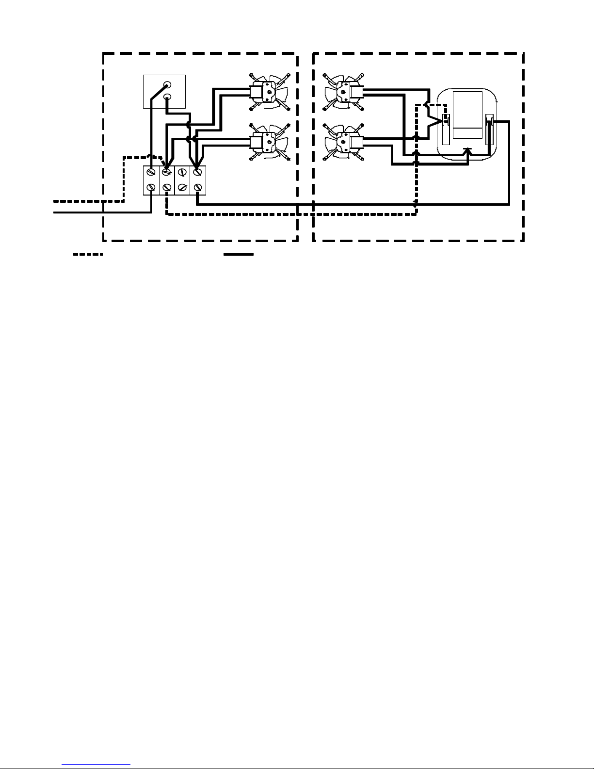
FWiring the system: Wire the system in accordance with local code and the wiring diagrams. Electrical connections
are made to the terminal strip in the fan/coil and the compressor in the condensing unit. (Figure 3) The fan/coil unit
requires a standard 110 volt, 60 Hz properly grounded electrical source which must be rated for a minimum ampres
in accordance with sizing guide.
WKS 2200 05/06 PG4
HOURS AND THEN EVACUATED TO HOLD A 250 MICRON VACUUM FOR A MINIMUM OF 15
MINUTES. (NOTE: THIS SHOULD TAKE ABOUT 6 HRS TO ACHIEVE) ANY LEAKS DISCOVERED
AFTER REFRIGERANT CHARGING ARE THE SOLE RESPONSIBILITY OF THE INSTALLER.
FCharging the system: After all components have been connected, pressure test the complete system for a minimum
of six hours. If no leaks are found, evacuate the system through both the liquid and suction service ports for a
minimum of six hours. Replace the insulation and cover on the fan/coil unit. With the system energized, slowly feed
refrigerant (R12 or R414A) into the suction service port until the suction pressure is equal to 35°F. If using R414a
there may be some bubbles in the sight glass. Allow the system to operate for several hours and then recheck
the system pressures. Additional refrigerant may be required as the temperature of the enclosure is
lowered to approximately 55° or the ambient temperature at the condensing unit rises above the
temperature at which the unit was charged. The final set of gauge readings should be taken when the wine storage
area is at 55°F and the condenser area approximately 85°F.
OPERATION
On initial start-up the cooling unit will reduce the temperature of the enclosure slowly. The unit may run constantly or
cycle off for short periods. The time required to reach the desired temperature will vary, depending on the enclosure
construction and contents.
The thermostat is factory set to approximately 55°F. Unless the temperature falls below that which is desired, do not
change the thermostat setting for at least 3 days.
After initial cool down, the "on-off" cycle should be relatively constant. The percentage of "off " time will depend on
enclosure construction, contents, and the temperature surrounding the enclosure. If it is necessary to adjust the
temperature of the enclosure; adjust the thermostat to a colder temperature while the unit is running and to a warmer
temperature while the unit is off. If the operation of the unit is stopped, either by unplugging it or by turning the
thermostat, do not restart it for at lease 10 minutes.
THERMOSTAT
EVAP FANS COND FANS
COMPRESSOR
FAN COIL
CONDENSING UNIT
FIGURE 3
= WHITE (COMMON) = BLACK (LINE) GROUNDS NOT SHOWN
110 VOLTS

WKS 2200 05/06 PG5
MAINTENANCE
The BREEZAIRE cooling unit requires very little maintenance. At least once every three months the condenser coil
should be inspected and vacuumed to prevent any air blockage. The condenser coil, in the condensing unit is located out
side the enclosure. (Figure 2) Use a vacuum with a brush attachment to remove the lint or dirt that may reside between
the aluminum fins.
(WARNING) If the condenser coil becomes blocked preventing proper air flow the unit will over heat causing
a loss in cooling efficiency and will result in failure of the unit not covered under warranty.
ENCLOSURE PROBLEMS
BREEZAIRE is extremely proud of the quality and reliability of its products. Experience has shown that of the small
number of problems encountered, the large majority are due to improper unit selection or enclosure construction. Should
the cooling system be suspected of malfunctioning, check the temperature of the air being exhausted from the condenser
outlet. (Figure 2) If it is warm, the unit is working. A further check may be made by comparing the air temperature
entering the larger grill [Evaporator Intake] on the fan/coil unit with that leaving the smaller grill [Evaporator Outlet].
(Figure 1) If the air leaving the unit is at least 6oF less than the temperature entering, the unit is working properly.
In situations where the ambient relative humidity is very low, the desired enclosure relative humidity may not be achieved
without adding moisture. To add moisture to the enclosure only use slow, natural evaporation from a small porous water
container. Do not use a humidifier.
In some cases, improper placement or installation may cause the unit's performance to be degraded. The condensing
unit must have a constant supply of fresh air, less than 85oF. If the condensing unit is located in a confined area
with poor ventilation, the unit will not be able to reject the heat it is removing from the enclosure and a malfunctioning unit
will be suspected.
Obstruction to the free flow of fresh air into or out of the condensing unit for any reason can cause the unit to heat rather
than cool the enclosure.
Proper sealing of the enclosure through the use of a vapor barrier and weather stripping cannot be over emphasized. The
cooling system will not be able to maintain the proper conditions if fresh, moisture laden air is constantly being introduced
into an improperly sealed enclosure. Symptoms of this condition are; unit runs all the time with only a slight reduction in
enclosure temperature and/or water overflows from the unit.
One way of discovering gross air leaks is to stand inside the enclosure with the lights off, allow your eyes to adapt to the
dark and look for light showing through cracks in the walls or around the door. Also close the door on a piece of paper,
if you can pull the paper through the door seal, it means air and moisture are also entering into your enclosure.
Because of the temperature difference between the inside and outside, very small cracks can allow large amounts of
outside air into the enclosure. Please beware that moisture can pass through solid concrete, brick, paint, paper and
wood.
Often a newly constructed room contains fresh wood, paint, concrete and other building materials. These materials
contain large amounts of moisture. When placed into operation in this type of environment, the system will work harder
to remove this extra moisture resulting in increased "ON TIME". This condition can cause symptoms similar to a poorly
sealed enclosure, but will gradually go away.
In areas where the ambient relative humidity is very low, the desired enclosure relative humidity may not be achieved
without adding moisture. To add moisture to the enclosure use only slow, natural evaporation from a small water
container. Do not use a humidifier.
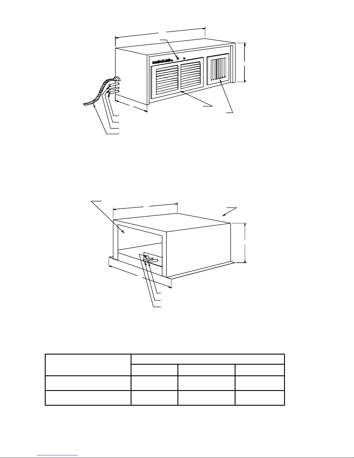
WKS 2200 05/06 PG6
Dimensions (inches)
BREEZAIRE
Models (A) (B) (C )
WKS 2200 Fan/Coil
(Figure 1) 22 11 8
WKS 2200 Condenser
(Figure 2) 14 10 12
3/8" OD DRAIN TUBE
1/4" LIQUID LINE
3/8" SUCTION LINE
110V ELECTRICAL CORD
EVAPORATOR INTAKE
EVAPORATOR OUTLET
THERMOSTAT
CONDENSER OUTLET
CONDENSER INTAKE
FAN/COIL UNIT
CONDENSING UNIT
FIGURE 1
FIGURE 2
A
B
C
A
C
B
3/8" SUCTION LINE
1/4" LIQUID LINE
ELECTRICAL WIRING
Table of contents
Other Breezaire Wine Cooler manuals


Popular Wine Cooler manuals by other brands

White and Brown
White and Brown TB 218 user manual

U-Line
U-Line Wine Captain 2260ZVVC User guide & service manual
 Use & installation guide")
Viking
Viking 15" (38.1 cm) Use & installation guide

Linea 2000
Linea 2000 DOMO DO909WK Instruction booklet

Svan
Svan SVN3600D2 Operating instruction

Vinotemp
Vinotemp WINE-MATE VINO1500HZD Use & care manual


