brent THE GRAIN TRAIN 740 User manual

- MODEL 740 -
Page 1
MODEL
740
THE GRAIN TRAIN WAGON
Model 740 Beginning With Serial Number B1576100
Unverferth
OPERATOR'S MANUAL
PARTS CATALOG
Division
ManufacturedAt:
®
Manufacturing Co., Inc.
27612 Temple Ave.
Shell Rock, IA 50670
PH: 319-885-6571 • Fax: 319-885-6576
Part #220718
®
®

- MODEL 740 -
Page 2 • 03-13-98
PAGE
INTRODUCTION ......................................................3
SAFETY ....................................................................4
SAFETY DECALS....................................................5
GRAIN WAGON MAINTENANCE AND SERVICE ...6
ELECTRICAL HOOK-UP .........................................8
ADJUSTABLE CHUTE.............................................9
SIDE BOARDS.........................................................9
BRAKE SYSTEM ...................................................10
DUAL WHEELS ..................................................... 12
PARTS SECTION
UNDERCARRIAGE ................................................14
BRAKES .................................................................16
WHEELS & TIRES, DUAL WHEELS ...................17
HUBS ......................................................................19
GRAVITY BOX.......................................................20
PAINT & DECALS ................................................. 22
SIDEBOARDS ........................................................23
DOOR WHEEL CHAIN REDUCTION...................24
DOOR WHEEL GEAR REDUCTION....................25
13" BRAKE WITH PARKING BRAKE ..................26
TONGUE................................................................. 28
FENDERS (Option) ................................................ 30
TARP (Option)........................................................ 32
TARP INSTALLATION...........................................34
UNLOADING AUGER (Available) .........................39
TABLE OF CONTENTS

- MODEL 740 -
Page 3
INTRODUCTION
Your new Brent Grain Train is designed to meet today's exacting operating re-
quirements. You have chosen a product with numerous operating features that will in-
crease your harvesting efficiency for years to come.
Your new Brent Grain Train will add the efficiency, flexibility, and dependability to
profit in today's agriculture.
The following pages will provide you with information regarding operating and
maintenanceinstructions. Use thisbookto familiarize yourselfwiththis new machineand
provide operating instructions to others.
THANK YOU FOR YOUR PURCHASE!
Please fill out and retain this portion for your records. For warranty consideration, please
contact dealer where purchased.
The serial number plate is located on the right side of the mast at center of machine
Date of Purchase Model Serial #
Owner name Farm/Co. name
Address City
State Zip Code Phone # ( )
Dealer City State
Please supply this information when you have questions or when ordering repair or re-
placement parts. Your dealer needs this information to give you prompt, efficient service.
•03-13-98
Wheel bolts tightened (re-check after initial use)
Tire pressures checked
Hardware tightened
Machinelubricated
Guards and shields in place
Safety and operating procedures reviewed
Fieldadjustmentinformationreviewed
Lubricationproceduresreviewed
Warrantyinformationreviewed
Hydraulichosesproperlyrouted/fittingstight
PRE-OPERATION CHECKLIST

- MODEL 740 -
Page 4
REMEMBER:
THINK SAFETY
A CAREFUL OPERATOR IS THE
BEST INSURANCE AGAINST AN
ACCIDENT!
OM-00229-A
No accident-prevention program can be successful without the whole-hearted
cooperation of the person who is directly responsible for the operation of the equipment.
To read accident reports from all over the country is to be convinced that a large
number of accidents can be prevented only by the operator anticipating the result before
the accident is caused and doing something about it. No power-driven equipment,
whether it be transportation or processing, whether it be on the highway, in the harvest
field, or in the industrial plant, can be safer than the person who is at the controls. If
accidents are to be prevented--and they can be prevented--it will be done by the
operators who accept the full measure of their responsibility.
It is true that the designer, the manufacturer, and the safety engineer can help;
and they will help, but their combined efforts can be wiped out by a single careless act
of the operator.
It is said that, "the best kind of a safety device is a careful operator." We, at
Unverferth Mfg. Co., Inc. ask that you be that kind of operator.
VERY IMPORTANT
DO NOT ALLOW ANYONE TO PLAY ON OR AROUND GRAIN WAGON.
IF ENTRANCE INTO GRAVITY BOX IS NECESSARY, USE EXTREME CAUTION. IF GRAVITY
BOX CONTAINS GRAIN OR OTHER MATERIALS, ENTRAPMENT IN SUCH MATERIALS MAY
CAUSE INJURY, SUFFOCATION, OR POSSIBLE LOSS OF LIFE.
DO NOT OVERLOAD GRAVITY BOX OR ADD MORE SIDE EXTENSIONS THAN WHAT IS
RECOMMENDED.
MAKE SURE A SLOW MOVING VEHICLE EMBLEM IS INSTALLED ON THE REAR OF THE
GRAIN WAGON.
TAKE THE TIME TO HOOK -UP YOUR LIGHTS.
UNIT IS TO BE TOWED AT TRACTOR SPEEDS ONLY - 25 MPH MAXIMUM.
PERSONAL INJURY AND DAMAGE TO UNIT MAY RESULT IF OVERRIDING STEERING
STOPS.

- MODEL 740 -
Page 5
IMPORTANT
Replace lost, damaged, painted, or unreadable decals
immediately. If parts that have decals are replaced, also make
sure to install new decals. These decalsinform andremind the
operator with operational information and safety messages.

- MODEL 740 -
Page 6 • 08-19-97
IMPORTANT CHECK POINTS
1. Check all wheel nuts for tightness before first load. Failure to do so may damage wheel
seats. Once seats are damaged, it will become impossible to keep nuts tight. Torque
to 400 Ft. Lbs. (dry). Re-tighten after first load and check periodically afterward.
2. Check toe-in. Improper toe
will cause excessive tire wear.
Toe should be set at 1/16 per
side. To adjust toe, set turn-
ing assembly perpendicular to
front axle. Then use straight
edge or sight front tire straight
with rear tire. Once straight,
turn 1/16". Tighten locknuts.
3. Grease all lube points daily during busy season:
A. 2 on each front spindle pivot
B. 4 on turning assembly pivot
C. 1 on each tie rod end
D. 2 on tongue on telescope latch plate.
MAINTENANCE AND SERVICING INFORMATION
4. Tire pressure: All truck tires..........Approximately 65 Lbs.
5. Wheel hubs (check grease after first season of use.)
Note: The bearings are pressure packed with grease. An empty hub cavity
does not indicate a lack of grease. It is not beneficial to fill the cavity.
6. Maintain brake fluid level in master cylinder. Lubricate push pipe and guides to ensure
free movement. Adjust brake shoes as necessary: Rotate wheel for forward movement
only. Turn cog until shoes drag, turn back cog 1-1/2 turns (20 cogs). See "Brake
System" for detailed instructions.
7. When hauling corrosive materials such as fertilizers, it is advisable after use to wash out
all excess materials to prevent premature rusting.
220911
•IMPORTANT
It is extremely important that the spindles are never welded to by the customer.
Special manufacturing processes are utilized at the factory, and spindle weldments should
always be replaced if repairs are necessary.
TIRES
Any questions or needs concerning
new tire performance should be
directed to your local tire dealer. Used
tires carry no warranty.
SER
VICE

- MODEL 740 -
Page 7
•03-13-98
300903
TONGUE AND WHEEL ALIGNMENT
1. Use a straight edge or string to set front tires straight with rear tires.
2. Loosen right and left tie rod clamps.
3. Adjust distances "L" from the hitch pin to the right and left king pins equal on each side
until tonque is perpendicular to front axle.
4. Again check that front and rear wheels are in a straight line. Set 1/16" Toe-In at front
of each wheel. Tighten tie rod clamps.
5. Check tracking of wagon.
Please refer to the following information for specific tongue/wheel alignment. If the
tongue does not pull perpendicular to the front axle, the grain wagon can "dog-track".
SER
VICE

- MODEL 740 -
Page 8
Your Grain Train Wagon is supplied with a seven-point SAE connector plug which
will adapt to the receptacle found on several new tractors on the market today. If
not available, an SAE J S60A seven-point outlet socket can be purchased from your
Unverferth dealer (order Part #92824).
ELECTRICAL HOOK-UP
220913
220912
The following schematic complies with ANSI/ASAE Standard S279.9/SAEJ137 for
new production tractors. NOTE: Wiring specifications may be different for older
tractor models. Consult your tractor operator's manual or dealer for proper wiring
and installation.
THE GRAIN TRAIN WIRES
Green -- Ground
Brown -- Right amber flashing lamp
Red -- Left amber flashing lamp
Yellow -- Tail light
SAE SEVEN POINT
CONNECTOR PLUG
SER
VICE

- MODEL 740 -
Page 9
ADJUSTABLE CHUTE
220937
Your grain wagon is equipped with an adjustable unloading chute-height feature. The
adjustment bolt is located under the door area of the grain wagon. When the bolt is turned
in (clockwise), the chute unload height decreases. When the bolt is turned out (counter-
clockwise), the chute height is raised.
Therightand left sideboardsand center bracketare pre-assembled. An end board (frontor rear)
is banded to the assembly with foam protection. The banded assemblies are stored on the front
and rear angle brackets on each side of the box. Three bolts hold each assembly in place. The
center bracket is bolted to the brace tube angle bracket (see inset).
IMPORTANT: AT LEAST TWO INDIVIDUALS ARE REQUIRED TO ERECT THE SIDE BOARDS.
To erect the side boards, remove three fasteners (each side) and cut the banding. Turn front and
rear boards into position and install fasteners but do not tighten. Tilt side assemblies into position
and install fasteners. Install the angle braces and cross brace if applicable. The fasteners
supplied are 3/8 x 3/4 flange screws and flange nuts. NOTE: Have a longer capscrew on hand if
required for seating the boards initially. After all boards are in position, tighten fasteners.
SIDE BOARDS
220943
•03-13-98
SER
VICE
- MODEL 740 -
Page 10
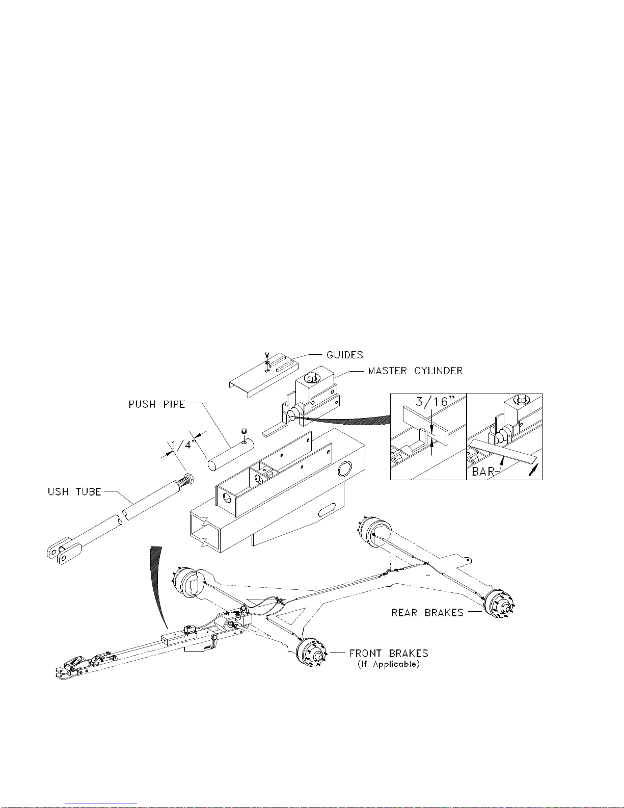
SLIDING HITCH AND LATCH
The braking system on your running gear is designed to release automatically when
you back up. Before adjusting individual brake shoes, inspect the master cylinder
push pipe and push tube for proper contact when the sliding hitch and latch
mechanism is pulled forward. Note: A minimum 1/4" gap is necessary to prevent
possible "dragging" of brakes.
Check the push pipe for alignment and lubricate to ensure free movement in the
tongue bracket. Lubricate guides on bottom of cover. The master cylinder "L"
bracket should be 3/16" above the tongue bracket sides. To prevent possible
interference, do not overtighten cover capscrew.
MASTER CYLINDER
Brake fluid level may be checked by removing cap on master cylinder. Refill level
with a heavy-duty brake fluid that meets or exceeds DOT-3. Do not clean any brake
components in gasoline, kerosene, or oil.
BRAKE SYSTEM
220918
• 09-06-96
•
SER
VICE

- MODEL 740 -
Page 11
BRAKE SHOE ADJUSTMENT
NOTE: Be sure to read preceding section on sliding hitch and latch adjustment
before proceeding to this step.
Brakes are set at factory, however, it may become necessary to adjust shoes after
the first season. The brakes incorporate a "Back-up" feature that makes it necessary
to rotate the wheels in the direction of forward rotation only when making adjust-
ments. Jack up each wheel, turn adjustment cog wheel located in slot on the brake
backing plate until brake shoes drag, then turn back cog wheel approximately
1-1/2 turns (20 cogs).
BRAKE BLEEDING
Use ONLY quality DOT-3 heavy-duty brake fluid.
If pressure bleeding equipment is available, follow the manufacturer's instructions in
bleeding the system.
MANUAL BLEEDING:
Fill master cylinder with fluid. Bleed rear brakes first (farthest from master cylinder).
Loosen the bleeder screw located in wheel cylinder one turn. The system is now
open to the atmosphere through a passage drilled in the screw. Securely install
bleeder hose to bleed screw on first wheel cylinder to be bled.
Submerge the loose end of bleeder hose in a glass container filled approximately
1/3 full with brake fluid to observe expelled air bubbles while stroking master cylinder.
NOTE: The bleed hose must have a snug connection at bleed screw and remain
submerged in brake fluid to avoid re-entry of air into the system.
Position a flat tool bar between master cylinder "L" bracket and housing (see
illustration) and pump master cylinder with long steady strokes. Continue to stroke
master cylinder until bubbles stop rising to surface of fluid in glass jar. Remove hose
and re-tighten bleeder screw
Repeat bleeding operation at each wheel cylinder. During the bleeding process,
replenish the brake fluid, so the level does not fall below the 1/2 full level in the
master cylinder reservoir. After bleeding is completed, make sure master cylinder
reservoir is filled and filler cap is securely in place.
WARNING
Saltwater, granular fertilizers and other corrosive materials are destructive to metal.
To prolong the life of a braking system used under corrosive conditions, flush the
actuator periodically with a high pressure water hose. Be sure to re-grease bearings
and oil all moving parts after the unit has dried. At the end of the season, when unit
is to be stored, remove the brake drums and clean inside the brakes. Pack wheel
bearings before drum is installed. CAUTION: Do not pack hub full of grease.
Excessive grease may leak into brake drums causing brake failure.
• 05-19-97
•
SER
VICE
- MODEL 740 -
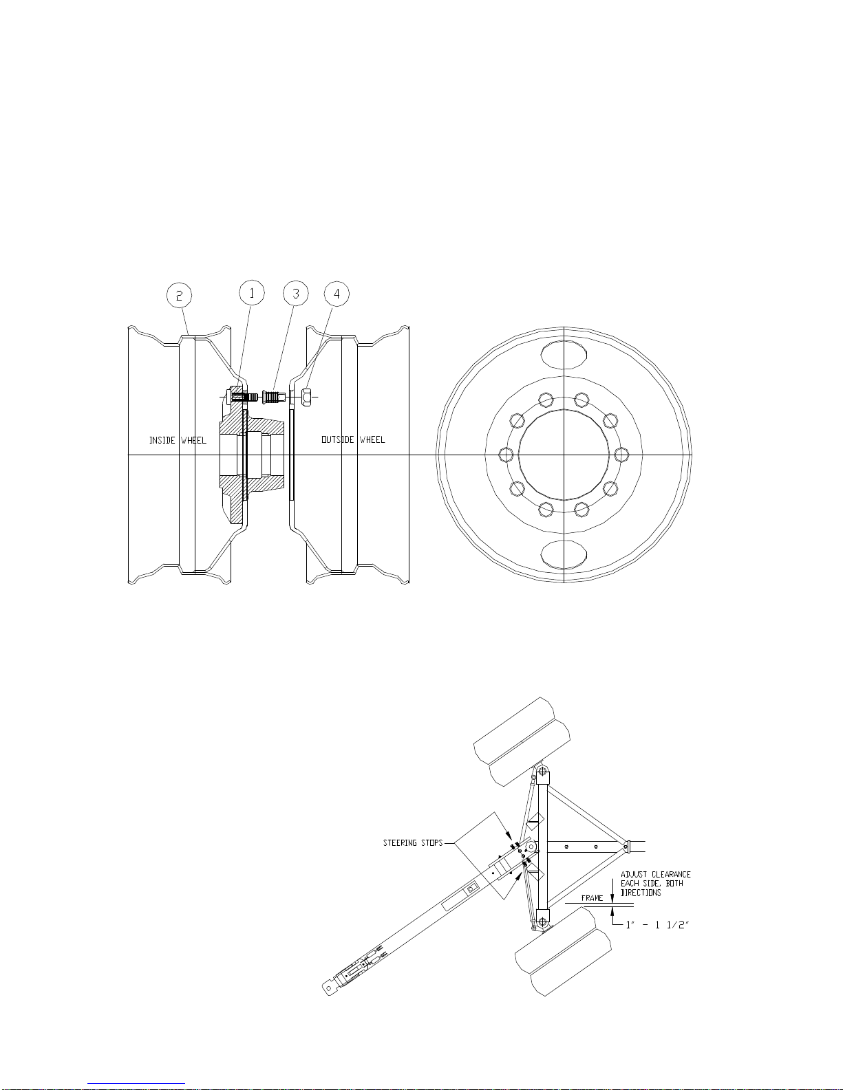
Page 12
Raise axle and block adequately for wheel and tire removal.
1. Install inside wheel over ten existing wheel studs (3/4 UNF). Install male/female
wheel nuts to secure inside wheel. Torque to 400 Ft. Lbs.
2. Install outside wheel on wheel nuts.
3. Install outer wheel nuts (1 1/8 UNF) to secure outside wheel. Torque to
400 Ft. Lbs.
DUAL WHEELS
220928
AXLE STOP ADJUSTMENT:
Turn wheels both directions
on level ground and adjust
axle stop bolts for 1 - 1 1/2"
clearance between inside tire
edge and nearest frame.
220928
• 08-19-97
SER
VICE

- MODEL 740 -
Page 13
NOTES
SER
VICE

- MODEL 740 -
Page 14
220904
•08-19-97
PARTS

- MODEL 740 -
Page 15
•08-19-97
1RearAxleWeldment 300102 1
2RearAxle Retainer 300099 1
3Capscrew, 3/4-10 UNC x 8 9390-161 1
4Undercarriage Pin, Rear 220147 21 x 2 1/2"
Hair Pin, #6 92424 4
5FrontAxleWeldment 300302 1
6RightFrontSpindle Assembly 300140 1Includes Item 7
LeftFrontSpindle Assembly 300141 1Includes Item 7
7BrassBushing 800394 42 1/2 x 2 x 2-1/2
8King Pin 300014 2
9Capscrew, 1/2-13 UNC x 3 9390-107 2
Nut, 1/2-13 UNC Centerlock 94981 2
10 ThrustBearing 92433 2
11 BrakeAssembly 4See Pages 14 & 24
12 HubAssembly 4See Page 17
13 Tie Rod Complete 300004 2Includes Items 14-16
Tie Rod only 8-402026 1
14 Tie Rod End RH Thread 92581 2
Tie Rod End LH Thread 92580 2
15 Tie Rod Clamps 93668 4
16 Tie Rod Nut 92579 4
Cotter Pin 9391-037 2
17 TurningAssembly 300077 1Includes Item 18
18 Bronze Bushing 92578 2
19 Capscrew, 3/4-10 UNC x 3 94733 4Tongue Stop
Nut, 3/4-10 UNC Jam 9395-016 4
20 TongueAssembly 1See Page 26
21 Grommet, Small 9001815 1Wiring,Tongue
22 King Pin 300005 1
23 Capscrew, 1/2-13 UNC x 3-1/2 9390-109 2
Nut, 1/2-13 UNC Centerlok 94981 2
24 Torsion Bar Weldment 300084 1
25 Undercarriage Pin 220005 11 x 6"
26 Cotter Pin, 1/8 x 2 9391-027 2
27 Pin,Torsion Bar 220151 11 x 4 3/4"
28 Spring, Torsion Bar 9001349 114 1/4"
29 Shaft, Spring 300083 1
30 Pin 220249 11 x 2-9/16
31 Hair Pin Cotter 92424 4
32 Spring Retainer Weldment 300100 1
33 Nut, 1-8 UNC Hex 9394-020 2
ITEMDESCRIPTION PART NO.QTY.NOTES
UNDERCARRIAGE
P
ARTS

- MODEL 740 -
Page 16 • 03-13-98
BRAKE PARTS
220934
INSET
1Brake Hose, 18 7/8" 94089 1 2 Male-Female
2BrakeLine,12" Bundyweld 92570 1 1
3Brake Hose, 12 1/8" 92569 2 1 Female-Female
4Cross 300184 -1Inverted Flare
5Capscrew, 1/4-20 UNC x 1 1/4 9390-006 -2
Lockwasher, 1/4 9404-017 -2
Nut, 1/4-20 UNC x 1 1/4 9394-002 -2
6Clip 9464 6 6
7BrakeLine,30" Bundyweld 92568 2 2
8Brake Hose, 13" 9461 2 2
9BrakeLine,98" Bundyweld 9000962 1 1
10 BrakeLine,16" Bundyweld 9001063 1 1
11 BrakeLine,45" Bundyweld 92818 2 2
12 BrakeTee 9465 3 1
13 Capscrew, 5/16-18 UNC x 3/4 9390-028 2 1
Lockwasher, 5/16 9404-019 2 1
Nut, 5/16-18 UNC 9394-004 2 1
14 BrakeLine,4-1/2" Bundyweld 92817 1-
15 Brake Drum 92575 4 4
16 Brake Cluster Page 24 4 4
17 Capscrew, 1/2-20 UNF x 1 9390-323 16 16
Lockwasher, 1/2 9404-025 16 16
Nut 1/2-20 UNF 9394-009 16 16
ITEMDESCRIPTION PART NO.QTY.QTY.NOTES
•
•
•
PARTS

- MODEL 740 -
Page 17
1Wheel&Tire Assembly 12154 418 x 22.5R Tire - Radial
Wheel&Tire Assembly 12125 418 x 22.5B Tire - Bias
Wheel only 95542 4W13x22.5 10 Bolt
2Valve Stem 93300 4
1Stud 3/4-16 UNF x 2 1/2 92457 Existing
2Wheel 9001991 88.25 x 24.5
Wheel&Tire Assembly 9001991/93236 811x24.5
3Nut, Inner Wheel 9001980 40
4Nut, Outer wheel 9001981 40
ITEMDESCRIPTION PART NO.QTY.NOTES
DUAL WHEELS - OPTION
ITEMDESCRIPTION PART NO.QTY.NOTES
WHEELS & TIRES
TIRES
Any questions or needs concerning
new tire performance should be
directed to your local tire dealer. Used
tires carry no warranty.
220936
220926
• 08-19-97
PARTS

- MODEL 740 -
Page 18
NOTES
P
ARTS

- MODEL 740 -
Page 19
CompleteHubAssembly 220417 4Includes Items 1-6, 10-13
1Seal, 3 3/8" I.D. 92829 133464TA
2Stud 92457 10
3Nut, 3/4-16 UNF Gr. 8 92458 10
4Outer Cup 92461 1453A
5Outer Bearing Cone 92463 1460
6Hub Cap 92466 1
7Cotter Key, 1/4 x 3 9391-062 1Repl. 92467
8Nut, 1 1/4-12 UNF 9393-024 1Repl. 92469
9Washer 92471 1
10 Screw 9390-026 4
11 Machined Hub w/Bearing Cups 220416 1Includes Items 2,4,12
12 Inner Cup 92475 133462
13 Inner Bearing Cone 92546 133275
220909
ITEMDESCRIPTION PART NO.QTY.NOTES
HUB
P
ARTS

- MODEL 740 -
Page 20
220906
•08-19-97
PARTS
Table of contents


