brenton PROMACH 4113 User guide

BEC Machine #4113
Revision Date - 17 July 2019
Prepared Especially For
JM Smuckers
CUSTOM
CARTONER
SYSTEM MANUAL

© 2019 Brenton Engineering. All Rights Reserved.
Section 106 of the 1976 Copyright Act forbids any party other than the author (Brenton Engineering Com-
pany) to: Reproduce owned work in copies or phonorecords, to prepare derivative works based upon the
work; to distribute copies or phonorecords of the work to the public by sale or other transfer of ownership,
by rental or lease. Copyright protection subsists from the time the work is created in fixed form. The copy-
right in the work of authorship immediately becomes the property of the author who created the work
(Brenton Engineering Company.) Only the author or those deriving their rights through the author can
rightfully claim copyright.
Liability Waiver
The information in this manual is subject to change without notice and does not represent a commitment
on the part of Brenton Engineering Company and assumes no responsibility for any errors that may appear
in this manual. In no event will Brenton Engineering Company or its employees, partners, contracted
workers/ companies or any association who participates in the writing of this manual be liable for technical
or editorial omissions made herein; nor for direct, indirect, special, incidental, or consequential damages
resulting from the use or defect of this manual.

Brenton Engineering Company JM Smuckers
Machine 4113 Cartoner
17 July 2019 Table of Contents
Page I
Table of Contents
Chapter 1: Introduction and Safety
Introduction. . . . . . . . . . . . . . . . . . . . . . . . . . . . . . . . . . . . . . . . . . . . . . . . . . . . . . . . . . . . 1-1
Warranty Information . . . . . . . . . . . . . . . . . . . . . . . . . . . . . . . . . . . . . . . . . . . . . . . . 1-1
Outside Manufacturer's Components . . . . . . . . . . . . . . . . . . . . . . . . . . . . . . 1-1
Brenton Engineering Components . . . . . . . . . . . . . . . . . . . . . . . . . . . . . . . . 1-1
About this Manual . . . . . . . . . . . . . . . . . . . . . . . . . . . . . . . . . . . . . . . . . . . . . . . . . . 1-2
Copyright Notice . . . . . . . . . . . . . . . . . . . . . . . . . . . . . . . . . . . . . . . . . . . . . . . . . . . 1-2
General Terms and Conditions of Sale . . . . . . . . . . . . . . . . . . . . . . . . . . . . . . . . . . 1-3
Safety. . . . . . . . . . . . . . . . . . . . . . . . . . . . . . . . . . . . . . . . . . . . . . . . . . . . . . . . . . . . . . . . . 1-4
BEC System Safety Recommendations . . . . . . . . . . . . . . . . . . . . . . . . . . . . . . . . . 1-4
Hazard Messages . . . . . . . . . . . . . . . . . . . . . . . . . . . . . . . . . . . . . . . . . . . . . . . . . . 1-5
Operation Safety . . . . . . . . . . . . . . . . . . . . . . . . . . . . . . . . . . . . . . . . . . . . . . . . . . . 1-6
Maintenance Safety. . . . . . . . . . . . . . . . . . . . . . . . . . . . . . . . . . . . . . . . . . . . . . . . . 1-7
Security Interlock Switch . . . . . . . . . . . . . . . . . . . . . . . . . . . . . . . . . . . . . . . . . . . . . 1-8
Electrical Lockout and Tagout Recommendations . . . . . . . . . . . . . . . . . . . . . . . . . 1-9
Pneumatic Lockout and Tagout Recommendations . . . . . . . . . . . . . . . . . . . . . . . 1-10
Installation and First Time Power Up . . . . . . . . . . . . . . . . . . . . . . . . . . . . . . . . . . . . . . 1-11
Installation Procedure . . . . . . . . . . . . . . . . . . . . . . . . . . . . . . . . . . . . . . . . . 1-11
Machine Power Requirements . . . . . . . . . . . . . . . . . . . . . . . . . . . . . . . . . . 1-11
Machine Air Pressure Requirements . . . . . . . . . . . . . . . . . . . . . . . . . . . . . 1-11
Remove Skids. . . . . . . . . . . . . . . . . . . . . . . . . . . . . . . . . . . . . . . . . . . . . . . 1-11
Emergency Stop Location Drawing . . . . . . . . . . . . . . . . . . . . . . . . . . . . . . . . . . . . . . . 1-13
Chapter 2: System Description
Machine Overview . . . . . . . . . . . . . . . . . . . . . . . . . . . . . . . . . . . . . . . . . . . . . . . . . . . . . . 2-1
Major Components . . . . . . . . . . . . . . . . . . . . . . . . . . . . . . . . . . . . . . . . . . . . . . . . . 2-1
Bag Alignment Conveyor . . . . . . . . . . . . . . . . . . . . . . . . . . . . . . . . . . . . . . . 2-1
Allen Bradley PV+7-1200 HMI . . . . . . . . . . . . . . . . . . . . . . . . . . . . . . . . . . . 2-1
Carton Magazine. . . . . . . . . . . . . . . . . . . . . . . . . . . . . . . . . . . . . . . . . . . . . . 2-1
Carton Set-up . . . . . . . . . . . . . . . . . . . . . . . . . . . . . . . . . . . . . . . . . . . . . . . . 2-1
Bag Racetrack Conveyor . . . . . . . . . . . . . . . . . . . . . . . . . . . . . . . . . . . . . . . 2-2
Bag Dual Pick & Place . . . . . . . . . . . . . . . . . . . . . . . . . . . . . . . . . . . . . . . . . 2-2
Cognex Vision At Bag Placement Station. . . . . . . . . . . . . . . . . . . . . . . . . . . 2-2
Loaded Plano Reject Station . . . . . . . . . . . . . . . . . . . . . . . . . . . . . . . . . . . . 2-2
Carton Forming. . . . . . . . . . . . . . . . . . . . . . . . . . . . . . . . . . . . . . . . . . . . . . . 2-2
Nordson Hot Melt Glue System . . . . . . . . . . . . . . . . . . . . . . . . . . . . . . . . . . 2-2
90-degree Discharge Pusher . . . . . . . . . . . . . . . . . . . . . . . . . . . . . . . . . . . . 2-2
I/O . . . . . . . . . . . . . . . . . . . . . . . . . . . . . . . . . . . . . . . . . . . . . . . . . . . . . . . . . 2-3
Guarding . . . . . . . . . . . . . . . . . . . . . . . . . . . . . . . . . . . . . . . . . . . . . . . . . . . . 2-3
Operational Review . . . . . . . . . . . . . . . . . . . . . . . . . . . . . . . . . . . . . . . . . . . . . . . . . 2-3
Pack Patterns . . . . . . . . . . . . . . . . . . . . . . . . . . . . . . . . . . . . . . . . . . . . . . . . . . . . . 2-4
Machine Floor Plan. . . . . . . . . . . . . . . . . . . . . . . . . . . . . . . . . . . . . . . . . . . . . . . . . . . . . . 2-5

JM Smuckers Brenton Engineering Company
Cartoner Machine 4113
Table of Contents 17 July 2019
Page II
Chapter 3: System Operation
Operating Procedures . . . . . . . . . . . . . . . . . . . . . . . . . . . . . . . . . . . . . . . . . . . . . . . . . . . 3-1
Starting the Machine . . . . . . . . . . . . . . . . . . . . . . . . . . . . . . . . . . . . . . . . . . . . . . . . 3-1
Shutting Down the Machine. . . . . . . . . . . . . . . . . . . . . . . . . . . . . . . . . . . . . . . . . . . 3-1
Loading Corrugated Blanks into the Magazines . . . . . . . . . . . . . . . . . . . . . . . . . . . 3-2
Placing the Machine into Jog Mode. . . . . . . . . . . . . . . . . . . . . . . . . . . . . . . . . . . . . 3-2
From an Emergency Stop . . . . . . . . . . . . . . . . . . . . . . . . . . . . . . . . . . . . . . . 3-2
From a Production Run. . . . . . . . . . . . . . . . . . . . . . . . . . . . . . . . . . . . . . . . . 3-2
Operator Control Panels . . . . . . . . . . . . . . . . . . . . . . . . . . . . . . . . . . . . . . . . . . . . . . . . . 3-3
The Main Electrical Enclosure (CP1). . . . . . . . . . . . . . . . . . . . . . . . . . . . . . . . . . . . 3-3
The HMI Left Side (CP2) . . . . . . . . . . . . . . . . . . . . . . . . . . . . . . . . . . . . . . . . . . . . . 3-4
HMI Right Side (CP3) . . . . . . . . . . . . . . . . . . . . . . . . . . . . . . . . . . . . . . . . . . . . . . . 3-6
Infeed Left Operator Station (CP4) . . . . . . . . . . . . . . . . . . . . . . . . . . . . . . . . . . . . . 3-8
Infeed Right Operator Station (CP5) . . . . . . . . . . . . . . . . . . . . . . . . . . . . . . . . . . . . 3-9
Infeed Left Operator Station (CP6) . . . . . . . . . . . . . . . . . . . . . . . . . . . . . . . . . . . . 3-10
Discharge Right Operator Station (CP7) . . . . . . . . . . . . . . . . . . . . . . . . . . . . . . . . 3-11
Glue Control Panel . . . . . . . . . . . . . . . . . . . . . . . . . . . . . . . . . . . . . . . . . . . . . . . . 3-12
The Human Machine Interface. . . . . . . . . . . . . . . . . . . . . . . . . . . . . . . . . . . . . . . . . . . . 3-13
The Numeric Keypad . . . . . . . . . . . . . . . . . . . . . . . . . . . . . . . . . . . . . . . . . . . . . . . 3-13
The System Information Screen . . . . . . . . . . . . . . . . . . . . . . . . . . . . . . . . . . . . . . 3-14
The Main Screen . . . . . . . . . . . . . . . . . . . . . . . . . . . . . . . . . . . . . . . . . . . . . . . . . . 3-15
The Menu Screen . . . . . . . . . . . . . . . . . . . . . . . . . . . . . . . . . . . . . . . . . . . . . . . . . 3-17
The Glue Control Screen. . . . . . . . . . . . . . . . . . . . . . . . . . . . . . . . . . . . . . . . . . . . 3-19
The Glue Control Purge Screen . . . . . . . . . . . . . . . . . . . . . . . . . . . . . . . . . . . . . . 3-25
The Active Alarms Screen . . . . . . . . . . . . . . . . . . . . . . . . . . . . . . . . . . . . . . . . . . . 3-27
The Alarm History Screen . . . . . . . . . . . . . . . . . . . . . . . . . . . . . . . . . . . . . . . . . . . 3-28
The VFD Fault Codes Screen . . . . . . . . . . . . . . . . . . . . . . . . . . . . . . . . . . . . . . . . 3-30
The Pack Select Screen . . . . . . . . . . . . . . . . . . . . . . . . . . . . . . . . . . . . . . . . . . . . 3-31
The Auto Adjust Teach Screen . . . . . . . . . . . . . . . . . . . . . . . . . . . . . . . . . . . . . . . 3-32
Setting Auto Adjust Positions . . . . . . . . . . . . . . . . . . . . . . . . . . . . . . . . . . . 3-34
The Jog SOL Control Screen. . . . . . . . . . . . . . . . . . . . . . . . . . . . . . . . . . . . . . . . . 3-35
The Manual Control Screen. . . . . . . . . . . . . . . . . . . . . . . . . . . . . . . . . . . . . . . . . . 3-36
The Reference Main Servo Screen . . . . . . . . . . . . . . . . . . . . . . . . . . . . . . . . . . . . 3-38
The Axis Reference Auto Adjust Servo Screen . . . . . . . . . . . . . . . . . . . . . . . . . . . 3-41
The Maintenance Global Settings Screen . . . . . . . . . . . . . . . . . . . . . . . . . . . . . . . 3-43
The Disable Bypass Options Screen . . . . . . . . . . . . . . . . . . . . . . . . . . . . . . . . . . . 3-45
The Barcode Scanner Screen . . . . . . . . . . . . . . . . . . . . . . . . . . . . . . . . . . . . . . . . 3-46
The Open Flap Detect Screen . . . . . . . . . . . . . . . . . . . . . . . . . . . . . . . . . . . . . . . . 3-47
The Bag Reject Clear Fault Prompt. . . . . . . . . . . . . . . . . . . . . . . . . . . . . . . . . . . . 3-49
The Pressure Regulators Screen . . . . . . . . . . . . . . . . . . . . . . . . . . . . . . . . . . . . . 3-50
The Shutdown Screen . . . . . . . . . . . . . . . . . . . . . . . . . . . . . . . . . . . . . . . . . . . . . . 3-52
Instrumentation & Controls . . . . . . . . . . . . . . . . . . . . . . . . . . . . . . . . . . . . . . . . . . . . . . 3-53
Security Interlock Switch . . . . . . . . . . . . . . . . . . . . . . . . . . . . . . . . . . . . . . . . . . . . 3-53
Pneumatic Controls . . . . . . . . . . . . . . . . . . . . . . . . . . . . . . . . . . . . . . . . . . . . . . . . . . . . 3-54
The Pneumatic Discharge Valve Assembly. . . . . . . . . . . . . . . . . . . . . . . . . . . . . . 3-54
Instrumentation . . . . . . . . . . . . . . . . . . . . . . . . . . . . . . . . . . . . . . . . . . . . . . . . . . . . . . . 3-55

Brenton Engineering Company JM Smuckers
Machine 4113 Cartoner
17 July 2019 Table of Contents
Page III
Adjustment Scales . . . . . . . . . . . . . . . . . . . . . . . . . . . . . . . . . . . . . . . . . . . . . . . . . 3-55
The Information & Alarm History Displays . . . . . . . . . . . . . . . . . . . . . . . . . . . . . . . . . 3-56
Alarm Messages . . . . . . . . . . . . . . . . . . . . . . . . . . . . . . . . . . . . . . . . . . . . . . . . . . 3-56
Warning Messages . . . . . . . . . . . . . . . . . . . . . . . . . . . . . . . . . . . . . . . . . . . . . . . . 3-78
Chapter 4: Troubleshooting
Sequence Of Operation . . . . . . . . . . . . . . . . . . . . . . . . . . . . . . . . . . . . . . . . . . . . . . . . . . 4-1
Initial Conditions Before Startup . . . . . . . . . . . . . . . . . . . . . . . . . . . . . . . . . . . . . . . 4-1
Naming Conventions . . . . . . . . . . . . . . . . . . . . . . . . . . . . . . . . . . . . . . . . . . . . . . . . 4-1
Carton Magazine and Carton Setup . . . . . . . . . . . . . . . . . . . . . . . . . . . . . . . . . . . . 4-2
Bag Conveyors . . . . . . . . . . . . . . . . . . . . . . . . . . . . . . . . . . . . . . . . . . . . . . . . . . . . 4-3
Loader 2 Bag Gantry . . . . . . . . . . . . . . . . . . . . . . . . . . . . . . . . . . . . . . . . . . . . . . . . 4-4
The Carton Forming and Inspection Station . . . . . . . . . . . . . . . . . . . . . . . . . . . . . . 4-5
Loader 4, Glue, and Compression. . . . . . . . . . . . . . . . . . . . . . . . . . . . . . . . . . . . . . 4-6
Sensor Functions . . . . . . . . . . . . . . . . . . . . . . . . . . . . . . . . . . . . . . . . . . . . . . . . . . . . . . . 4-7
Retro-Reflective Sensors. . . . . . . . . . . . . . . . . . . . . . . . . . . . . . . . . . . . . . . . . . . . . 4-8
Diffuse Sensors . . . . . . . . . . . . . . . . . . . . . . . . . . . . . . . . . . . . . . . . . . . . . . . . . . . . 4-9
Inductive Proximity Sensor . . . . . . . . . . . . . . . . . . . . . . . . . . . . . . . . . . . . . . . . . . 4-10
Sensor Descriptions. . . . . . . . . . . . . . . . . . . . . . . . . . . . . . . . . . . . . . . . . . . . . . . . 4-11
Light Tree Status Indicator. . . . . . . . . . . . . . . . . . . . . . . . . . . . . . . . . . . . . . . . . . . 4-18
Troubleshooting . . . . . . . . . . . . . . . . . . . . . . . . . . . . . . . . . . . . . . . . . . . . . . . . . . . . . . . 4-19
VFD Settings . . . . . . . . . . . . . . . . . . . . . . . . . . . . . . . . . . . . . . . . . . . . . . . . . . . . . 4-22
Infeed Conv Drive 501 . . . . . . . . . . . . . . . . . . . . . . . . . . . . . . . . . . . . . . . . 4-22
Discharge Conv Drive 601 . . . . . . . . . . . . . . . . . . . . . . . . . . . . . . . . . . . . . 4-23
Vacuum Blower Drive 701 . . . . . . . . . . . . . . . . . . . . . . . . . . . . . . . . . . . . . 4-24
Chapter 5: Changeover and Maintenance
Lockout and Tagout Recommendations . . . . . . . . . . . . . . . . . . . . . . . . . . . . . . . . . . . . 5-1
Electrical System . . . . . . . . . . . . . . . . . . . . . . . . . . . . . . . . . . . . . . . . . . . . . . . . . . . 5-1
Pneumatic and Vacuum Systems . . . . . . . . . . . . . . . . . . . . . . . . . . . . . . . . . . . . . . 5-2
Changeover. . . . . . . . . . . . . . . . . . . . . . . . . . . . . . . . . . . . . . . . . . . . . . . . . . . . . . . . . . . . 5-2
How to use Changeover . . . . . . . . . . . . . . . . . . . . . . . . . . . . . . . . . . . . . . . . . . . . . 5-2
Changeover Location Drawing . . . . . . . . . . . . . . . . . . . . . . . . . . . . . . . . . . . . . . . . 5-3
Changeover Quick Reference Charts . . . . . . . . . . . . . . . . . . . . . . . . . . . . . . . . . . . 5-4
Pictorial Changeover . . . . . . . . . . . . . . . . . . . . . . . . . . . . . . . . . . . . . . . . . . . . . . . . 5-5
Completing the Changeover . . . . . . . . . . . . . . . . . . . . . . . . . . . . . . . . . . . . . . . . . 5-16
Maintenance . . . . . . . . . . . . . . . . . . . . . . . . . . . . . . . . . . . . . . . . . . . . . . . . . . . . . . . . . .5-17
Electrical P.M. . . . . . . . . . . . . . . . . . . . . . . . . . . . . . . . . . . . . . . . . . . . . . . . . . . . . 5-17
Control Enclosures . . . . . . . . . . . . . . . . . . . . . . . . . . . . . . . . . . . . . . . . . . . . . . . . 5-17
Junction Boxes . . . . . . . . . . . . . . . . . . . . . . . . . . . . . . . . . . . . . . . . . . . . . . . . . . . 5-17
Sensing Devices . . . . . . . . . . . . . . . . . . . . . . . . . . . . . . . . . . . . . . . . . . . . . . . . . . 5-17
Daily Inspections . . . . . . . . . . . . . . . . . . . . . . . . . . . . . . . . . . . . . . . . . . . . . . . . . . 5-18
Weekly Inspections . . . . . . . . . . . . . . . . . . . . . . . . . . . . . . . . . . . . . . . . . . . . . . . . 5-18
Three-Month Preventative Maintenance . . . . . . . . . . . . . . . . . . . . . . . . . . . . . . . . 5-19
Pulleys & Sprockets. . . . . . . . . . . . . . . . . . . . . . . . . . . . . . . . . . . . . . . . . . . . . . . . 5-20

JM Smuckers Brenton Engineering Company
Cartoner Machine 4113
Table of Contents 17 July 2019
Page IV
Drive Chains . . . . . . . . . . . . . . . . . . . . . . . . . . . . . . . . . . . . . . . . . . . . . . . . . . . . . 5-20
Replacing Vertical Linear Bearings on Gantry’s . . . . . . . . . . . . . . . . . . . . . . . . . . 5-21
Referencing Positions . . . . . . . . . . . . . . . . . . . . . . . . . . . . . . . . . . . . . . . . . . . . . . 5-24
Axis 2 Downstream. . . . . . . . . . . . . . . . . . . . . . . . . . . . . . . . . . . . . . . . . . . 5-24
Axis 2 Upstream . . . . . . . . . . . . . . . . . . . . . . . . . . . . . . . . . . . . . . . . . . . . . 5-25
Axis 3 Downstream. . . . . . . . . . . . . . . . . . . . . . . . . . . . . . . . . . . . . . . . . . . 5-26
Axis 3 Upstream . . . . . . . . . . . . . . . . . . . . . . . . . . . . . . . . . . . . . . . . . . . . . 5-27
Axis 4 Upstream . . . . . . . . . . . . . . . . . . . . . . . . . . . . . . . . . . . . . . . . . . . . . 5-28
Non-Wash Down Sections Cleaning & Sanitation . . . . . . . . . . . . . . . . . . . . . . . . . 5-29
Wash Down Procedure . . . . . . . . . . . . . . . . . . . . . . . . . . . . . . . . . . . . . . . . . . . . . 5-30
Cleaning Methods. . . . . . . . . . . . . . . . . . . . . . . . . . . . . . . . . . . . . . . . . . . . 5-30
Lubrication . . . . . . . . . . . . . . . . . . . . . . . . . . . . . . . . . . . . . . . . . . . . . . . . . . . . . . . . . . . 5-31
Lubrication Location Drawing . . . . . . . . . . . . . . . . . . . . . . . . . . . . . . . . . . . . . . . . 5-32
200 Hour Linear Bearing Grease Zerk Lubrications . . . . . . . . . . . . . . . . . . . . . . . 5-33
Loader 1 Lubrication . . . . . . . . . . . . . . . . . . . . . . . . . . . . . . . . . . . . . . . . . . 5-33
Loader 2 Lubrication . . . . . . . . . . . . . . . . . . . . . . . . . . . . . . . . . . . . . . . . . . 5-35
Loader 3 Lubrication . . . . . . . . . . . . . . . . . . . . . . . . . . . . . . . . . . . . . . . . . . 5-37
Loader 4 Lubrication . . . . . . . . . . . . . . . . . . . . . . . . . . . . . . . . . . . . . . . . . . 5-39
400 Hour Linear Bearing Grease Zerk Lubrications . . . . . . . . . . . . . . . . . . . . . . . 5-41
Infeed Linear Bearings . . . . . . . . . . . . . . . . . . . . . . . . . . . . . . . . . . . . . . . . 5-41
Glue Conveyor Auto Adjust Lubrications . . . . . . . . . . . . . . . . . . . . . . . . . . 5-42
Carton Forming Conveyor. . . . . . . . . . . . . . . . . . . . . . . . . . . . . . . . . . . . . . 5-43
Carton Flights . . . . . . . . . . . . . . . . . . . . . . . . . . . . . . . . . . . . . . . . . . . . . . . 5-44
Maintenance Log . . . . . . . . . . . . . . . . . . . . . . . . . . . . . . . . . . . . . . . . . . . . . . . . . . 5-46
Spare Parts List & Bill of Materials . . . . . . . . . . . . . . . . . . . . . . . . . . . . . . . . . . . . . . . . 5-47
Spare Parts Legend. . . . . . . . . . . . . . . . . . . . . . . . . . . . . . . . . . . . . . . . . . . . . . . . 5-47
Code & Description . . . . . . . . . . . . . . . . . . . . . . . . . . . . . . . . . . . . . . . . . . . 5-47
Chapter 6: Electrical Programs & Prints
Appendix A: Index

Brenton Engineering Company JM Smuckers
Machine 4113 Cartoner
17 July 2019 List of Figures
Page I
List of Figures
Chapter 1: Introduction and Safety
E-Stop Buttons. . . . . . . . . . . . . . . . . . . . . . . . . . . . . . . . . . . . . . . . . . . . . . . . . . . . . 1-6
Security Interlock Switch . . . . . . . . . . . . . . . . . . . . . . . . . . . . . . . . . . . . . . . . . . . . . 1-8
Electrical Lock Out. . . . . . . . . . . . . . . . . . . . . . . . . . . . . . . . . . . . . . . . . . . . . . . . . . 1-9
Pneumatic Lock Out . . . . . . . . . . . . . . . . . . . . . . . . . . . . . . . . . . . . . . . . . . . . . . . 1-10
E- Stop Location Drawing . . . . . . . . . . . . . . . . . . . . . . . . . . . . . . . . . . . . . . . . . . . 1-13
Chapter 2: System Description
Machine Floor Plan . . . . . . . . . . . . . . . . . . . . . . . . . . . . . . . . . . . . . . . . . . . . . . . . . 2-5
Chapter 3: System Operation
The Magazine . . . . . . . . . . . . . . . . . . . . . . . . . . . . . . . . . . . . . . . . . . . . . . . . . . . . . 3-2
Control Panel 2 . . . . . . . . . . . . . . . . . . . . . . . . . . . . . . . . . . . . . . . . . . . . . . . . . . . . 3-4
Control Panel 3 . . . . . . . . . . . . . . . . . . . . . . . . . . . . . . . . . . . . . . . . . . . . . . . . . . . . 3-6
Control Panel 4 . . . . . . . . . . . . . . . . . . . . . . . . . . . . . . . . . . . . . . . . . . . . . . . . . . . . 3-8
Control Panel 5 . . . . . . . . . . . . . . . . . . . . . . . . . . . . . . . . . . . . . . . . . . . . . . . . . . . . 3-9
Control Panel 6 . . . . . . . . . . . . . . . . . . . . . . . . . . . . . . . . . . . . . . . . . . . . . . . . . . . 3-10
Control Panel 7 . . . . . . . . . . . . . . . . . . . . . . . . . . . . . . . . . . . . . . . . . . . . . . . . . . . 3-11
The Glue Tank. . . . . . . . . . . . . . . . . . . . . . . . . . . . . . . . . . . . . . . . . . . . . . . . . . . . 3-12
Example Numeric Keypad . . . . . . . . . . . . . . . . . . . . . . . . . . . . . . . . . . . . . . . . . . . 3-13
The System Info Screen . . . . . . . . . . . . . . . . . . . . . . . . . . . . . . . . . . . . . . . . . . . . 3-14
The Main Screen . . . . . . . . . . . . . . . . . . . . . . . . . . . . . . . . . . . . . . . . . . . . . . . . . . 3-15
The Menu Screen . . . . . . . . . . . . . . . . . . . . . . . . . . . . . . . . . . . . . . . . . . . . . . . . . 3-17
The Glue Control Screen. . . . . . . . . . . . . . . . . . . . . . . . . . . . . . . . . . . . . . . . . . . . 3-19
The Glue Control Purge Screen . . . . . . . . . . . . . . . . . . . . . . . . . . . . . . . . . . . . . . 3-25
The Active Alarms Screen . . . . . . . . . . . . . . . . . . . . . . . . . . . . . . . . . . . . . . . . . . . 3-27
The Alarm History Screen . . . . . . . . . . . . . . . . . . . . . . . . . . . . . . . . . . . . . . . . . . . 3-28
The VFD Fault Codes Screen . . . . . . . . . . . . . . . . . . . . . . . . . . . . . . . . . . . . . . . . 3-30
The Pack Select Screen . . . . . . . . . . . . . . . . . . . . . . . . . . . . . . . . . . . . . . . . . . . . 3-31
The Auto Adjust Teach Screen . . . . . . . . . . . . . . . . . . . . . . . . . . . . . . . . . . . . . . . 3-32
The Auto Adjust Teach Screen . . . . . . . . . . . . . . . . . . . . . . . . . . . . . . . . . . . . . . . 3-34
The Jog SOL Control Screen. . . . . . . . . . . . . . . . . . . . . . . . . . . . . . . . . . . . . . . . . 3-35
The Manual Control Screen. . . . . . . . . . . . . . . . . . . . . . . . . . . . . . . . . . . . . . . . . . 3-36
The Reference Main Servo Screen . . . . . . . . . . . . . . . . . . . . . . . . . . . . . . . . . . . . 3-38
The Reference Auto Adjust Servo Screen. . . . . . . . . . . . . . . . . . . . . . . . . . . . . . . 3-41
The Maintenance Global Settings Screen . . . . . . . . . . . . . . . . . . . . . . . . . . . . . . . 3-43
The Disable/ Bypass Options Screen . . . . . . . . . . . . . . . . . . . . . . . . . . . . . . . . . . 3-45
The Barcode Screen . . . . . . . . . . . . . . . . . . . . . . . . . . . . . . . . . . . . . . . . . . . . . . . 3-46
The Open Flap Detect Screen . . . . . . . . . . . . . . . . . . . . . . . . . . . . . . . . . . . . . . . . 3-47
The Bag Reject Clear Fault Prompt. . . . . . . . . . . . . . . . . . . . . . . . . . . . . . . . . . . . 3-49
The Pressure Regulator Screen . . . . . . . . . . . . . . . . . . . . . . . . . . . . . . . . . . . . . . 3-50

JM Smuckers Brenton Engineering Company
Cartoner Machine 4113
List of Figures 17 July 2019
Page II
The Shutdown Screen . . . . . . . . . . . . . . . . . . . . . . . . . . . . . . . . . . . . . . . . . . . . . . 3-52
The Security Interlock . . . . . . . . . . . . . . . . . . . . . . . . . . . . . . . . . . . . . . . . . . . . . . 3-53
Pneumatic Supply Components . . . . . . . . . . . . . . . . . . . . . . . . . . . . . . . . . . . . . . 3-54
Typical Adjustment Scale . . . . . . . . . . . . . . . . . . . . . . . . . . . . . . . . . . . . . . . . . . . 3-55
Chapter 4: Troubleshooting
Carton Magazine and Setup . . . . . . . . . . . . . . . . . . . . . . . . . . . . . . . . . . . . . . . . . . 4-2
Bag Placing Station . . . . . . . . . . . . . . . . . . . . . . . . . . . . . . . . . . . . . . . . . . . . . . . . . 4-3
Bag Loader Gantry . . . . . . . . . . . . . . . . . . . . . . . . . . . . . . . . . . . . . . . . . . . . . . . . . 4-4
Carton Forming Gantry . . . . . . . . . . . . . . . . . . . . . . . . . . . . . . . . . . . . . . . . . . . . . . 4-5
Loader 4 Compression Gantry. . . . . . . . . . . . . . . . . . . . . . . . . . . . . . . . . . . . . . . . . 4-6
The Retro-reflective Sensor. . . . . . . . . . . . . . . . . . . . . . . . . . . . . . . . . . . . . . . . . . . 4-8
The Retro-reflective Sensor Blocked . . . . . . . . . . . . . . . . . . . . . . . . . . . . . . . . . . . . 4-8
The Diffuse Sensor . . . . . . . . . . . . . . . . . . . . . . . . . . . . . . . . . . . . . . . . . . . . . . . . . 4-9
The Diffuse Sensor Blocked . . . . . . . . . . . . . . . . . . . . . . . . . . . . . . . . . . . . . . . . . . 4-9
The Inductive Sensor. . . . . . . . . . . . . . . . . . . . . . . . . . . . . . . . . . . . . . . . . . . . . . . 4-10
The Inductive Sensor Blocked . . . . . . . . . . . . . . . . . . . . . . . . . . . . . . . . . . . . . . . . 4-10
Chapter 5: Changeover and Maintenance
Changeover Location Drawing . . . . . . . . . . . . . . . . . . . . . . . . . . . . . . . . . . . . . . . . 5-3
The Tool 4 Change Out (x2) Adjustment . . . . . . . . . . . . . . . . . . . . . . . . . . . . . . . . . 5-6
The Tool 4 - Compression (x4) Adjustment . . . . . . . . . . . . . . . . . . . . . . . . . . . . . . . 5-7
The Tool 3 - Upstream Adjustment . . . . . . . . . . . . . . . . . . . . . . . . . . . . . . . . . . . . . 5-8
The Tool 3 - Downstream Adjustment . . . . . . . . . . . . . . . . . . . . . . . . . . . . . . . . . . . 5-9
The Infeed Conveyor Downstream Adjustment . . . . . . . . . . . . . . . . . . . . . . . . . . . 5-10
The Infeed Conveyor Upstream Adjustment . . . . . . . . . . . . . . . . . . . . . . . . . . . . . 5-11
The Mag Height Hand Crank Adjustment . . . . . . . . . . . . . . . . . . . . . . . . . . . . . . . 5-12
The Magazine Clips Adjustment . . . . . . . . . . . . . . . . . . . . . . . . . . . . . . . . . . . . . . 5-13
The HMI Pack Pattern Change . . . . . . . . . . . . . . . . . . . . . . . . . . . . . . . . . . . . . . . 5-14
Barcode Scanner Reading Barcode on Magazine. . . . . . . . . . . . . . . . . . . . . . . . . 5-15
Barcode Scanner Screen. . . . . . . . . . . . . . . . . . . . . . . . . . . . . . . . . . . . . . . . . . . . 5-15
Loader Head Bolts . . . . . . . . . . . . . . . . . . . . . . . . . . . . . . . . . . . . . . . . . . . . . . . . . 5-21
Face Plate Removal . . . . . . . . . . . . . . . . . . . . . . . . . . . . . . . . . . . . . . . . . . . . . . . 5-22
Servo and Non-Servo Sides . . . . . . . . . . . . . . . . . . . . . . . . . . . . . . . . . . . . . . . . . 5-22
Bearing Rails . . . . . . . . . . . . . . . . . . . . . . . . . . . . . . . . . . . . . . . . . . . . . . . . . . . . . 5-23
Axis 2 Downstream Reference Measurement . . . . . . . . . . . . . . . . . . . . . . . . . . . . 5-24
Axis 2 Upstream Reference Measurement . . . . . . . . . . . . . . . . . . . . . . . . . . . . . . 5-25
Axis 3 Downstream Reference Measurement . . . . . . . . . . . . . . . . . . . . . . . . . . . . 5-26
Axis 3 Upstream Reference Measurement . . . . . . . . . . . . . . . . . . . . . . . . . . . . . . 5-27
Axis 4 Upstream Reference Measurement . . . . . . . . . . . . . . . . . . . . . . . . . . . . . . 5-28
The Lubrication Location Drawing . . . . . . . . . . . . . . . . . . . . . . . . . . . . . . . . . . . . . 5-32
Loader 1 Side 1 Horizontal Lubrication Locations . . . . . . . . . . . . . . . . . . . . . . . . . 5-33
Loader 1 Side 2 Horizontal Lubrication Locations . . . . . . . . . . . . . . . . . . . . . . . . . 5-33
Loader 1 Side 1 Vertical Lubrication Locations . . . . . . . . . . . . . . . . . . . . . . . . . . . 5-34
Loader 1 Side 2 Vertical Lubrication Locations . . . . . . . . . . . . . . . . . . . . . . . . . . . 5-34

Brenton Engineering Company JM Smuckers
Machine 4113 Cartoner
17 July 2019 List of Figures
Page III
Loader 2 Side 1 Horizontal Lubrication Locations . . . . . . . . . . . . . . . . . . . . . . . . . 5-35
Loader 2 Side 2 Horizontal Lubrication Locations . . . . . . . . . . . . . . . . . . . . . . . . . 5-35
Loader 2 Side 1 Vertical Bank Lubrication Locations . . . . . . . . . . . . . . . . . . . . . . 5-36
Loader 2 Side 2 Vertical Bank Lubrication Locations . . . . . . . . . . . . . . . . . . . . . . 5-36
Loader 3 Side 1 Horizontal Lubrication Locations . . . . . . . . . . . . . . . . . . . . . . . . . 5-37
Loader 3 Side 2 Horizontal Lubrication Locations . . . . . . . . . . . . . . . . . . . . . . . . . 5-37
Loader 3 Side 1 Vertical Lubrication Locations . . . . . . . . . . . . . . . . . . . . . . . . . . . 5-38
Loader 3 Side 2 Vertical Lubrication Locations . . . . . . . . . . . . . . . . . . . . . . . . . . . 5-38
Loader 4 Side 1 Horizontal Lubrication Locations . . . . . . . . . . . . . . . . . . . . . . . . . 5-39
Loader 4 Side 2 Horizontal Lubrication Locations . . . . . . . . . . . . . . . . . . . . . . . . . 5-39
Loader 4 Side 1 Vertical Lubrication Locations . . . . . . . . . . . . . . . . . . . . . . . . . . . 5-40
Loader 4 Side 2 Vertical Lubrication Locations . . . . . . . . . . . . . . . . . . . . . . . . . . . 5-40
Infeed Linear Bearings. . . . . . . . . . . . . . . . . . . . . . . . . . . . . . . . . . . . . . . . . . . . . . 5-41
Glue Conveyor Auto Adjust Linear Bearing . . . . . . . . . . . . . . . . . . . . . . . . . . . . . . 5-42
Glue Conveyor Auto Adjust Linear Bearing . . . . . . . . . . . . . . . . . . . . . . . . . . . . . . 5-42
Carton Forming Auto Adjust Linear Bearing . . . . . . . . . . . . . . . . . . . . . . . . . . . . . 5-43
Carton Forming Auto Adjust Linear Bearing . . . . . . . . . . . . . . . . . . . . . . . . . . . . . 5-43
Carton Flights Auto Adjust Linear Bearing. . . . . . . . . . . . . . . . . . . . . . . . . . . . . . . 5-44
Carton Flights Auto Adjust Linear Bearing. . . . . . . . . . . . . . . . . . . . . . . . . . . . . . . 5-44
Discharge Auto Adjust Linear Bearing. . . . . . . . . . . . . . . . . . . . . . . . . . . . . . . . . . 5-45
Discharge Auto Adjust Linear Bearing. . . . . . . . . . . . . . . . . . . . . . . . . . . . . . . . . . 5-45
Chapter 6: Electrical Programs & Prints
Appendix A: Index

JM Smuckers Brenton Engineering Company
Cartoner Machine 4113
List of Figures 17 July 2019
Page IV

Brenton Engineering Company JM Smuckers
Machine 4113 Cartoner
17 July 2019 Introduction and Safety Contents
Page I
Introduction and Safety Contents
Introduction. . . . . . . . . . . . . . . . . . . . . . . . . . . . . . . . . . . . . . . . . . . . . . . . . . . . . . . . . . . . 1-1
Warranty Information . . . . . . . . . . . . . . . . . . . . . . . . . . . . . . . . . . . . . . . . . . . . . . . . 1-1
About this Manual . . . . . . . . . . . . . . . . . . . . . . . . . . . . . . . . . . . . . . . . . . . . . . . . . . 1-2
Copyright Notice . . . . . . . . . . . . . . . . . . . . . . . . . . . . . . . . . . . . . . . . . . . . . . . . . . . 1-2
General Terms and Conditions of Sale . . . . . . . . . . . . . . . . . . . . . . . . . . . . . . . . . . 1-3
Safety. . . . . . . . . . . . . . . . . . . . . . . . . . . . . . . . . . . . . . . . . . . . . . . . . . . . . . . . . . . . . . . . . 1-4
BEC System Safety Recommendations . . . . . . . . . . . . . . . . . . . . . . . . . . . . . . . . . 1-4
Hazard Messages . . . . . . . . . . . . . . . . . . . . . . . . . . . . . . . . . . . . . . . . . . . . . . . . . . 1-5
Operation Safety . . . . . . . . . . . . . . . . . . . . . . . . . . . . . . . . . . . . . . . . . . . . . . . . . . . 1-6
Maintenance Safety. . . . . . . . . . . . . . . . . . . . . . . . . . . . . . . . . . . . . . . . . . . . . . . . . 1-7
Security Interlock Switch . . . . . . . . . . . . . . . . . . . . . . . . . . . . . . . . . . . . . . . . . . . . . 1-8
Electrical Lockout and Tagout Recommendations . . . . . . . . . . . . . . . . . . . . . . . . . 1-9
Pneumatic Lockout and Tagout Recommendations . . . . . . . . . . . . . . . . . . . . . . . 1-10
Installation and First Time Power Up . . . . . . . . . . . . . . . . . . . . . . . . . . . . . . . . . . . . . . 1-11
Emergency Stop Location Drawing . . . . . . . . . . . . . . . . . . . . . . . . . . . . . . . . . . . . . . . 1-13

JM Smuckers Brenton Engineering Company
Cartoner Machine 4113
Introduction and Safety Contents 17 July 2019
Page II

1.
Page 1-1
Brenton Engineering Company JM Smuckers
Machine 4113 Cartoner
17 July 2019 Introduction and Safety
Introduction and Safety
Introduction
Thank You for Purchasing this Brenton Engineering Cartoner!
If you have questions, or need assistance, feel free to contact our Service Department at:
Brenton Engineering Company
4750 CO. RD. 13 NE
Alexandria, MN 56308
320-852-7705
Warranty Information
Outside Manufacturer's Components
Items are considered outside manufacturer's components if they are not built at Brenton
Engineering; for example, Allen Bradley PLC's.
Your Brenton Engineering packaging system contains outside manufacturer's components.
In general, most companies offer a 90 day warranty. For specific information on outside
manufacturer's warranties, reference the VENDOR DATA MANUALS.
Brenton Engineering will repair or replace defective components covered by outside man-
ufacturers' warranties according to the provisions of each respective manufacturer's war-
ranty. Freight, labor, expenses, and service rates related to replacement parts under
warranty are invoiced at applicable standard rates.
Brenton Engineering Components
Standard Warranty: The document titled "General Terms and Conditions of Sale" contains
comprehensive Brenton Engineering warranty information. A copy of this document is
located on the in this section. In summary, it includes a 1 year, or 7500 operating hours,
guarantee on material and workmanship. This warranty excludes expendable components,
such as plastic wear guides, vacuum cups, etc.
Note: Changes to the electrical programs, or mechanical modifications
without written approval of Brenton Engineering Company, may
result in undesirable machine operations and will void the warranty.

JM Smuckers Brenton Engineering Company
Cartoner Machine 4113
Introduction and Safety 17 July 2019
Page 1-2
About this Manual
Brenton Engineering is committed to helping you maximize the productivity of your sys-
tem. This manual is specifically designed for your packaging system, to assist you in the
operation and maintenance of your new equipment. Please take the time to familiarize
yourself with the contents of this manual.
• Section 1 is the Introduction and Safety section. This section discusses safety, terms
and conditions of the sale, hazard messages, and installation information. An Emer-
gency Stop Location chart is provided at the end of this section.
• Section 2 is the System Description section. This section will discuss machine specifi-
cations including pack patterns, product dimensions and run speeds for each product.
Section 2 also includes a machine overview with a brief description of each section of
the machine. A Machine Layout Drawing is found at the end of this section.
• Section 3 is the System Operation section. This section describes the operator control
panels, the Human Machine Interface, and operational procedures.
• Section 4 is the Troubleshooting section. This section discusses the sequence of oper-
ation. In the sequence of operation, each part of the machine, including the various
sensor functions, is described as the product flows through the machine. Sensors are
described, including a chart of sensors found on the machine. A troubleshooting chart
is also found in the back of this section.
• Section 5 is the Changeover and Maintenance section. This section describes the lock-
out and tagout recommendations. This section’s main focus is the changeover steps
including pictures, charts, and a Changeover Location Drawing to aid the operator
during changeover adjustments. In this section you will also find a suggested mainte-
nance schedule including a maintenance log. A spare parts list and bill of material
concludes this section.
• Section 6 is the Electrical Programs section. This section is where the customer should
store copies of the system software. Electrical prints are folded and placed in this sec-
tion for your convenience.
• Section 7 is the Miscellaneous section. This section includes the shipping diagram and
a glossary of common terms.
Copyright Notice
© 2019 Brenton Engineering
Section 106 of the 1976 Copyright Act forbids any party other than the author (Brenton Engi-
neering) to: Reproduce owned work in copies or phonorecords, to prepare derivative works
based upon the work; to distribute copies or phonorecords of the work to the public by sale or
other transfer of ownership, by rental or lease.
Copyright protection subsists from the time the work is created in fixed form. The copyright
in the work of authorship immediately becomes the property of the author who created the
work (Brenton Engineering.) Only the author or those deriving their rights through the author
can rightfully claim copyright.

Brenton Engineering Company JM Smuckers
Machine 4113 Cartoner
17 July 2019 Introduction and Safety
Page 1-3
General Terms and Conditions of Sale
1. FORMATION OF CONTRACT: The terms and conditions set forth in this document constitute the offer of Brenton Engineering Com-
pany ("Seller") to sell the item(s) of sale (IOS) specified herein.
NO ACCEPTANCE SHALL BE EFFECTIVE WHICH VARIES THE TERMS AND CONDITIONS STATED IN THIS OFFER OR
PROPOSES ADDITIONAL TERMS. ANY NON-CONFORMING ACCEPTANCE SHALL BE DEEMED TO BE REJECTED
UNLESS EXPRESSLY APPROVED BY SELLER IN WRITING.
2. ACCEPTANCE: No order, sale, agreement to sell, accepted proposal, or contract of sale shall be binding unless accepted on Seller's
Order Acknowledgment form and signed by Seller's authorized representative.
3. WRITTEN TERMS EXCLUSIVE: This agreement, when accepted by Purchaser, constitutes a final written expression of all the terms
of this agreement and is a complete and exclusive statement of those terms. Any and all representations, promises, warranties or state-
ments by Seller's agent(s) that differ in any way from the terms of this written agreement shall be given no force or effect. Any subse-
quent changes to this agreement must be in writing and signed by both Seller and Purchaser to be effective.
4. PRICE: All prices are exclusive of federal, state, or local taxes, duties or fees. All such taxes, duties or fees shall be borne by Purchaser.
Where Seller has the legal obligation to collect the same, they will be added to the price or billed separately to Purchaser. A monthly
service charge of 1.5% per month (18% per year) or the highest rate allowed by law, whichever is lower, will accrue on accounts out-
standing more than 30 days.
5. SELLER RETAINS SECURITY INTEREST: Purchaser grants to Seller a security interest in the IOS and the proceeds thereof to secure
payment of the purchase price of the IOS Seller is authorized to file financing statements under the Uniform Commercial Code or other
statutes naming Purchaser as debtor and Seller as secured party and indicating that the IOS and the proceeds thereof are items of collat-
eral. Purchaser further agrees to execute within five (5) days following any request by Seller such financing statements as Seller shall
require for filing or recording of this agreement.
6. DELIVERY: Completion dates submitted are approximate. Furthermore, Seller shall not be liable for any delays in the delivery of
orders due in whole or in part, directly or indirectly, to fire, act of God, acts of war, strike, lack of raw materials, supplies or compo-
nents, retooling, upgrading of technology, delays of carriers, embargo, government order or directive, or any circumstance beyond
Seller's control. Purchaser agrees that Seller shall not be liable for any damages, including direct, indirect, consequential, or special
damages, which may result from any such delays.
7. INSPECTION AND ACCEPTANCE OF GOODS: Purchaser shall inspect the IOS at the factory of the Seller before shipment end shall
be deemed to have accepted the IOS upon Purchaser's signed approval for shipment.
8. SHIPPING AND COSTS: The IOS shall be delivered F.O.B. Seller's factory Carlos, MN (or as otherwise stated in the offer) and
shipped and installed by and at Purchaser's risk and expense, including shipping, insurance, handling and Installation costs.
9. WARRANTY: Seller warrants, to the original Purchaser only, that the equipment manufactured by Seller shall be free from defects In
material and workmanship for a period of twelve (12) months from the date of delivery or until the equipment has been operated for a
total of seven-thousand five-hundred (7,500) hours, whichever occurs earlier. Excluded from warranty are:
A. Failure due to misapplication or operation beyond rated capacity; b. Damage or failure due to lack of proper maintenance and
care, abuse, or operation contrary to the operating instructions of Seller; c. Item(s) altered by anyone other than Seller's autho-
rized Representative.
B. Any equipment found defective will be repaired or, at Seller's option, replaced. Defective equipment or parts, after factory autho-
rization, shall be returned to seller's designated receiving point, freight prepaid by the Purchaser. Seller will repair or replace the
defective part and return it to the Purchaser freight prepaid. Installation of the repaired or replaced parts is the Purchaser's respon-
sibility.
C. Items not manufactured by Seller but used in the manufacture of the IOS, and the IOS if not manufactured by Seller, are/is specif-
ically excluded from the Warranty, and are covered by the warranty, if any, of the item's manufacturer(s) and, Seller's obligation
shall be limited to the extent of the warranties so received by Seller from the item's manufacturer(s).
SELLER MAKES NO OTHER WARRANTY, EXPRESS OR IMPLIED. ANY OTHER WARRANTY, EXPRESS OR
IMPLIED, STATUTORY OR OTHERWISE, INCLUDING, WITH OUT LIMITATION, ANY WARRANTY OF MERCHANT-
ABILITY, FITNESS FOR A PARTICULAR PURPOSE OR USE, OR AGAINST INFRINGEMENT, IS HEREBY DIS-
CLAIMED BY SELLER AND EXCLUDED FROM ANY AGREEMENT MADE BY ACCEPTANCE OF THIS OFFER.
10. EXCLUSION OF CONSEQUENTIAL DAMAGES: UNDER NO CIRCUMSTANCES WHATSOEVER, INCLUDING IN THE
EVENT SELLER'S WARRANTY IS DEEMED TO HAVE FAILED OF ITS ESSENTIAL PURPOSE, SHALL SELLER BE LIABLE
FOR ANY CONSEQUENTIAL OR INCIDENTAL DAMAGES, LOSS OR EXPENSE (INCLUDING, WITHOUT LIMITATION,
LOSS OF PROFITS OR GOOD WILL) ARISING FROM THIS AGREEMENT, OR FROM THE USE OF OR INABILITY TO USE
THE IOS FURNISHED HEREUNDER WHETHER SUCH CLAIM IS BASED ON CONTRACT, NEGLIGENCE, STRICT TORT
OR WARRANTY.
11. NOTICE OF DEFECTS: Purchaser must inform Seller in writing of any detect in the IOS within ten (10) days after the IOS is put into
service, but not more than thirty (30) days after delivery to the Purchaser. Notice of any latent defects in material and workmanship, in
all instances, must be given within ten (10) days after discovery.
12. THIRD PARTY LIABILITY, AND REMEDIES: Seller also shall not be liable for loss, damage, or injury to persons or property of Pur-
chaser or third parties arising out of use, mis-use, or possession of any IOS sold under this agreement. Purchaser shall hold Seller harm-
less for all claims or actions brought by third parties with respect to any such claims or actions.
Full compliance with OSHA involves the installation and use of the equipment in the hands of the purchaser-owner. Seller cannot,
therefore, represent or certify that its equipment conforms in all respects with OSHA regulations. In view of this, if revisions are
required, Seller is prepared to quote extra charges for specific modifications at the request of the Purchaser, insofar as technically prac-
tical. This policy also applies to any other Federal, state, or local standards which might exist.
13. GOVERNING LAW/DISPUTES: This contract shall be governed by and interpreted in accordance with the internal laws (and not the
laws of conflicts) of the State of Minnesota. NO ACTION ARISING OUT OF THIS SALE MAY BE BROUGHT BY PURCHASER
MORE THAN ONE YEAR AFTER THE CAUSE OF ACTION HAS ACCRUED. in any action brought with respect to this contract or
the IOS sold thereunder, upon prevailing, Seller shall be entitled to its reasonable attorneys' fees, costs and disbursements.
14. NO LICENSE: The sale of the IOS by Seller does not constitute a license, implied or otherwise, for the use of any patents or know-how
of others, nor does it constitute a license implied or otherwise on patents or know-how of Seller except as such product itself is the sub-
ject of the claims of Seller's patent.
15. WAIVER: The failure of Seller to enforce at any time any of the provisions hereof shall not be construed to be a waiver of such provi-
sions nor the right of Seller to enforce such provisions in the future.
052892

JM Smuckers Brenton Engineering Company
Cartoner Machine 4113
Introduction and Safety 17 July 2019
Page 1-4
Safety
At Brenton Engineering Company (BEC), we are committed to building quality packaging
and material handling equipment. To achieve this, our machines must be efficient, easy to
maintain, and safe to operate.
Before attempting to operate the equipment, become familiar with the safety recommen-
dations and operational components of your Cartoner. You should also become familiar
with the technical information pertaining to components used within the system, including
their operating and safety features. This information is located in the Vendor Data Manual
and in other literature supplied with the equipment. To maximize machine safety and effi-
ciency you must operate the machine correctly and comply with the safety features
described.
Stay alert and remember: Safety is the responsibility of everyone who operates or ser-
vices your BEC system.
BEC System Safety Recommendations
Safeguarding personnel that operate and/or maintain automated equipment is the primary
consideration. Because it is very dangerous to enter the operating space (work envelope)
of a packaging system during automatic operation, adequate safeguards must be in place
and safety precautions must be observed.
The following general precautions are recommended for all personnel who perform sys-
tem operation or maintenance.
• Do lockout-tagout procedures whenever you do maintenance and repair work.
• All personnel who repair, maintain, or operate the equipment need to know the loca-
tion of all EMERGENCY STOP buttons. See Figure 1 - 5.
• Do not operate the equipment with any of the safety guards removed.
• Do not wear neckties, loose clothing, or long loose-hanging hair around any equip-
ment.
• Observe and follow the DANGER, WARNING, and CAUTION messages throughout
this manual, in vendor manuals, and displayed on the equipment.
• DO NOT use steps or stands that allow anyone to reach over guards.
• Personnel should attend all available safety and operational training courses.
• Personnel should know and follow the recommended safety procedures whenever
they must enter the packaging systems motion area.
• Personnel should not enter the packaging system while control power is "ON".
• Personnel should not power up the system if someone is in the packaging system.
• The packaging system should be powered down when not in use.
• Personnel should pay special attention to all the posted warnings and cautions located
on any devices. Observe all safety and/or precautionary steps and procedures when
working with the system.
• Personnel should keep the system clean to make it easier to spot hazards.

Brenton Engineering Company JM Smuckers
Machine 4113 Cartoner
17 July 2019 Introduction and Safety
Page 1-5
Hazard Messages
Notations appear on pages of this manual to alert the reader to important messages regard-
ing a significant hazard for personnel or equipment. These messages convey three levels
of risk as defined below. Failure to observe these instructions can result in death, serious
injury, damaged equipment, or loss of product or production.
DANGER Denotes the possibility of serious injury or death to personnel.
WARNING Denotes the possibility of potential injury or damage to equipment.
CAUTION Denotes the possibility of damage to product or an interruption of produc-
tion.
JM Smuckers Brenton Engineering Company
Cartoner Machine 4113
Introduction and Safety 17 July 2019
Page 1-6
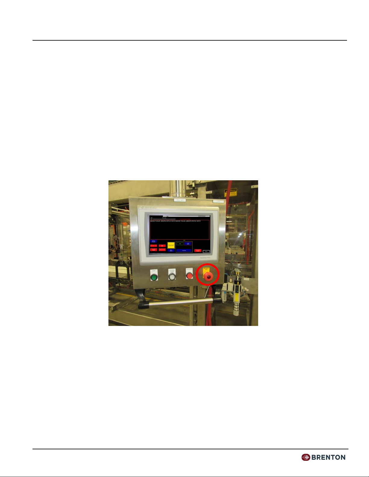
Operation Safety
The following safety precautions are recommended for all personnel who operate this
equipment.
• Operators should immediately report unsafe working conditions to a supervisor.
• The operator should understand the function of the entire system including all external
devices and equipment that interact with the system.
• Before starting operation, the operator should understand the complete task that the
system is designed to accomplish.
• The operator should know the location and functional status of all devices (switches,
sensors, control signals) that can cause the system to move.
• The operator should know where each EMERGENCY STOP button is located for
both main and external control devices.
• Do not hesitate to use an E-Stop in an emergency.
• After cycle stopping the machine, press the E-stop prior to entering the working path
of the machine. Do not rely on security interlocks alone.
• The operator should make sure all safety devices are functioning and periodically
checked for proper operation.
• The operator should ensure that all personnel are outside the system before starting
operation.
• The operator should never enter, or allow others to enter the system during automatic
operation.
Figure 1 - 1
E-Stop Buttons

Brenton Engineering Company JM Smuckers
Machine 4113 Cartoner
17 July 2019 Introduction and Safety
Page 1-7
Maintenance Safety
The following safety precautions are recommended for all personnel who are responsible
for the maintenance or service of this equipment.
• Personnel should ensure that all safety devices are functioning and periodically
checked for proper operation before performing maintenance.
• Before performing any maintenance, service, or inspection inside the main control
panel, the 3-phase power source should be turned off and locked out.
• When possible, maintenance should be performed on the system with the power OFF.
Lockout and tag out procedures should be followed to protect personnel from injury
and to indicate the equipment is being serviced.
• Personnel should pay careful attention to all devices that may be powered or capable
of motion, such as conveyors and pneumatic devices.
• Release or block all stored energy devices (hydraulic or pneumatic) that may present a
danger when working with the system. Before working with pneumatic devices, shut
off the air supply and purge the air lines.
• Be aware when removing a servomotor or brake that the associated mechanical part
will fall unless supported in some manner.
• Use only specified replacement parts. Never use non-specific fuses that have not been
specified Brenton Engineering. Potential fire and/or damage may result.
• Before restarting the system, ensure personnel are not in the system and that the sys-
tem and external devices are operating properly.
JM Smuckers Brenton Engineering Company
Cartoner Machine 4113
Introduction and Safety 17 July 2019
Page 1-8
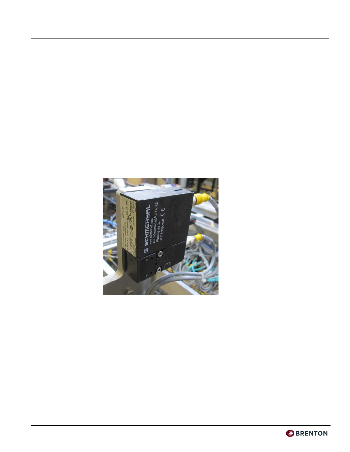
Security Interlock Switch
Brenton Engineering used an Interlock Switch, attached to each access door, to guard
against unsafe entry into this system. It interlocks the guard to the machine control system
and ensures machine power is isolated and remains isolated while the guard door is open.
The machine power flows through each of these switches. A mechanical actuator, typi-
cally mounted to the guard door itself, is used to actuate a switch that is in a separate
sealed case. The switch is wired to the machine control circuit. When the operator requires
access to the system, the operator must stop the machine prior to opening the interlocked
access door. The door is locked when the machine is running. When a door is open, the
machine cannot start.
Note: Brenton Engineering always recommends that the operator use a
controlled shutdown procedure using the Cycle Stop button and
then an Emergency Stop button.
Figure 1 - 2
Security Interlock
Switch
Table of contents
Popular Industrial Equipment manuals by other brands


Rockwell Automation
Rockwell Automation Allen-Bradley MegaDySC Dynamic Voltage Sag... user manual

Eaton
Eaton Airflex WCB Series Installation, operation and maintenance

Grizzly
Grizzly G9980 manual

Entes
Entes ENT-SC-325S manual

OMCA
OMCA SMV Use and maintenance manual

HYDAC International
HYDAC International CS 2000 Series Operating and maintenance instructions

Nitta
Nitta FP-200T Operator's manual

Eaton
Eaton Airflex RTK Installation, operation and maintenance manual

CONFLOW
CONFLOW GREEN GV Series Installation and maintenance manual

cashco
cashco P4 Installation, operation & maintenance manual

ABB
ABB HT612573 Operation manual

IMET Spa
IMET Spa VELOX 350 AF-NC User instructions