IOM-P4 3
SECTION VI
VI. MAINTENANCE
To prevent damage to body, use soft jaws when
placing body in a vise. Position so that vise closes
over the flats on lower end of body.
5
SPRING UNDER COMPRESSION. Prior to
removing spring chamber, relieve range spring
compression by turning knob CCW until rotation
comes to a complete stop. Failure to do so may
result in flying parts that could cause personal
injury.
WARNING
CAUTION
A. General:
1. Maintenance procedures hereinafter are
based upon removal of the regulator unit from
the pipeline where installed.
2. Owner should refer to owner's procedures for
removal, handling, cleaning and disposal of
nonreusable parts, i.e. gaskets, etc.
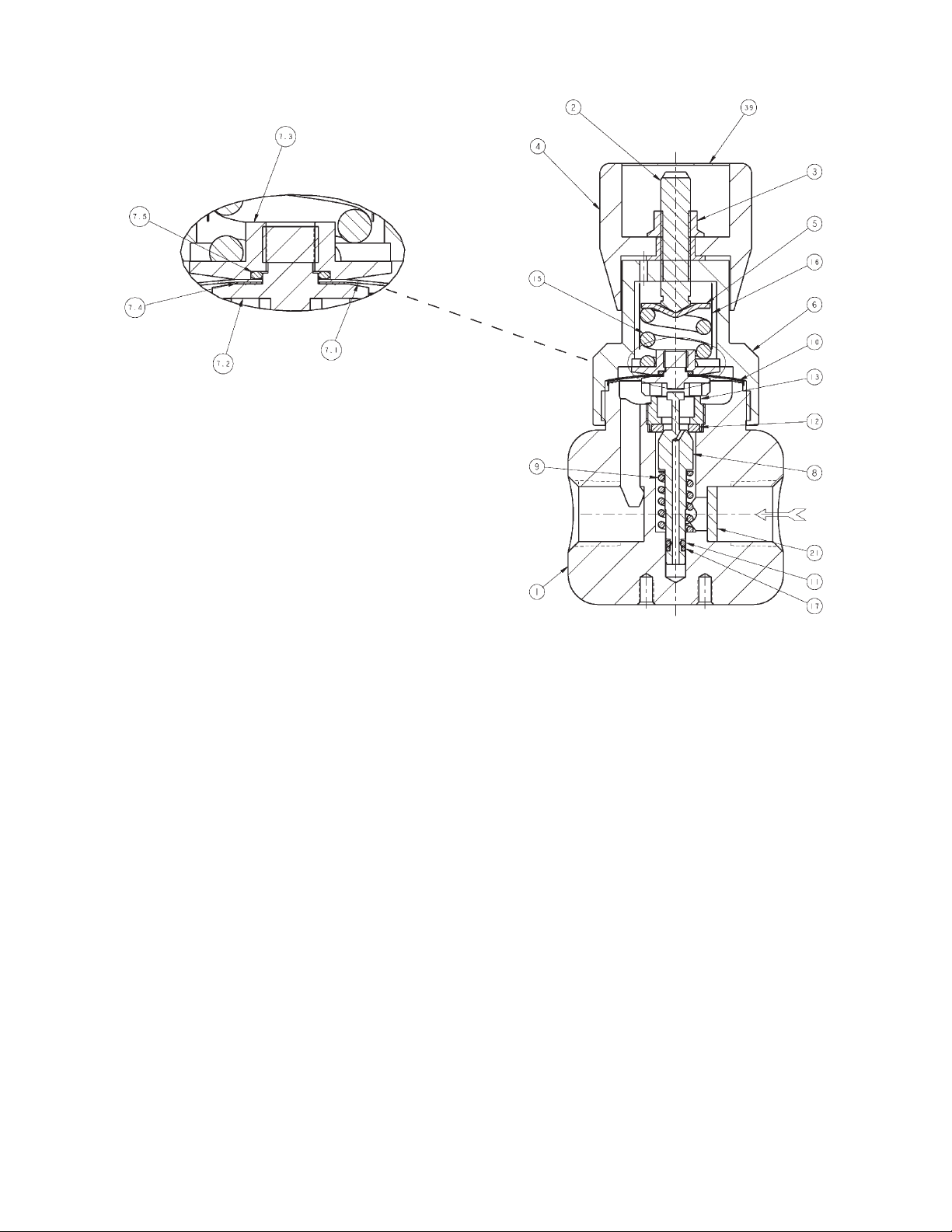
3. Refer to Figure 2 for basic regulator and Fig-
ure 1 for the diaphragm subassembly.
B. Diaphragm Replacement:
1. Securely install the body (1) in a vise with
knob (4) directed upwards.
2. Relax range spring (15) by turning knob (4)
CCW until rotation comes to a complete stop.
NOTE: It is not necessary to remove the knob
before removing the spring chamber (6) from
the body (1).
3. Remove spring chamber (6) by grasping the
flats and turning CCW. Upon removal, the
range spring (15), range spring clip (16), and
spring button (5) should remain inside the
spring chamber subassembly.
4. Remove diaphragm subassembly (7) consist-
ing of the actuator nut (7.3), diaphragm (7.1),
actuator post (7.2), actuator gasket (7.4),
actuator o-ring (7.5). Remove diaphragm
gasket (10).
5. Remove actuator nut (7.3) and separate all
parts of the diaphragm subassembly (7).
6. Clean body (1) diaphragm flange surface
and all reusable parts according to owner's
procedures. Do not scratch diaphragm
gasket seating surface. NOTE: On regu-
lators originally supplied as “oxygen clean”,
Option-M, maintenance must include a level
of cleanliness equal to Cashco's cleaning
standard #S-1134. On regulators originally
supplied for Sanitary Service, maintenance
must include a level of cleanliness equal to
Cashco cleaning standard #S-1576. Contact
factory for details.
7. Inspect and replace any necessary parts.
NOTE: Use only parts manufactured and
supplied by Cashco, Inc. for these products.
See Section VIII.
8. Reassemble diaphragm subassembly (7) by
placing the actuator gasket (7.4), diaphragm
(7.1), and actuator o-ring (7.5) over the
threads of the actuator post (7.2). Place a
thread sealant compound on the threads of
the actuator post (7.2) prior to installing the
actuator nut (7.3). Install actuator nut (7.3)
and tighten to the following torque value: 15
Ft-lbs (20 Nm).
9. Place the diaphragm gasket (10) onto the
body (1) diaphragm flange. Place diaphragm
subassembly (7) on top of the gasket (10).
10. Lubricate the threads of the body (1) with
a lightweight grease that is compatible with
service use. Rotate the spring chamber (6)
CW by hand onto the threaded portion of
the body (1) until firmly seated against the
diaphragm gasket (10). Tighten to the follow-
ing torque value: 65–70 Ft lbs (88–95 Nm).
11. Pressurize with air and spray liquid leak de-
tector around body (1) and spring chamber
(6) to test for leakage. Ensure that an outlet
pres
sure is maintained during this leak test
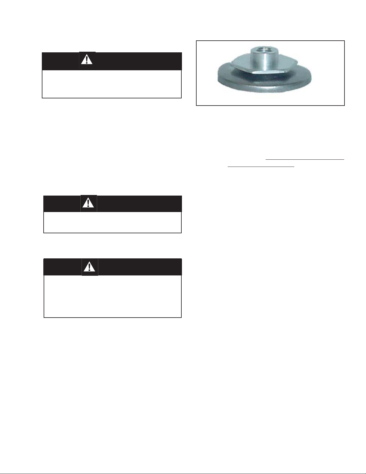
Figure 1: Diaphragm Subassembly
WARNING
SYSTEM UNDER PRESSURE. Prior to performing
any maintenance, isolate the regulator from the
system and relieve all pressure. Failure to do so
could result in personal injury.