Brew-Boss 2.06 User manual
Brew-Boss® V2.06 Operation Manual
Automated Electric Brewing System
Operation Manual V2.06
(For Brew-Boss® App Versions 1.27 and later)
www.Brew-Boss.com
Page 1
Brew-Boss® V2.06 Operation Manual
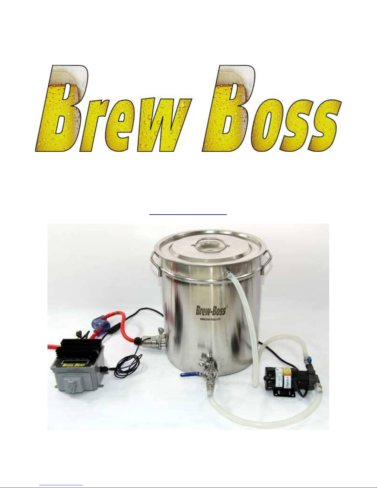
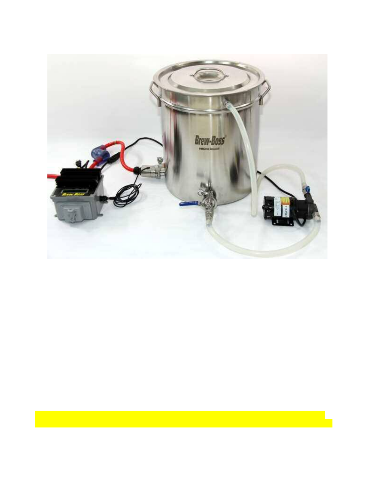
1 - System Overview
The Brew-Boss® home brew system is an all electric home brewing system that allows home brewers
to brew extract and all-grain recipes with complete and accurate automatic control of temperature and
timing. Complete systems are available in 10, 15, and 20 gallon versions in both 120VAC and 240VAC
options. The 10 gallon version produces a 5 gallon net batch, the 15 gallon version is capable of 10
gallon net batches, and the 20 gallon system is capable of 5, 10 and 15 gallon batches.
The Brew-Boss® System utilizes a power control box that controls one or two electric heater elements,
a recirculation pump, and an optional Hops Boss® automatic hops feeder. The Brew-Boss® controller
communicates with an Android Tablet App that provides a color touch screen graphical user interface
that allows complete control over the brewing process. All steps and parameters relative to the brewing
process can be modified by the user to control nearly any brew setup. It operates in a completely
Automatic mode, or can be operated in manual step mode for those that want manual control over their
brewing process. The base system provided operates as a Brew-in-a-Bag system with a single kettle. A
version is also available with a COFI Mash Infusion Filter that replaces the mesh bag in a BIAB system
and offers a few additional advantages. The controller will also control 2 and 3 vessel systems as well!
The Brew-Boss® controller interfaces with the Android tablet or iPad via a Wi-Fi interface.
The Brew-Boss®controller can be purchased as a part of a complete system or the controller can be
Page 2

Brew-Boss® V2.06 Operation Manual
purchased separately to add to your existing system.
Brew-Boss®system can be supplied as a Brew-In-A-Bag (BIAB) or with our patented COFI mash
infusion system.
Complete systems include the following components:
10, 15, or 20 Gallon Stainless Steel Kettle with Petcock Valve and Side Mounted Recirculation
Accessory Port
3500 or 5500 Watt Electric Heating Element for 240 Volt Systems or Dual 1500 Watt Elements
for 120VAC 10 Gallon Version
Microprocessor Controlled Brew-Boss® Brew Controller with LCD Display and Integrated
WiFi Router
High Temperature Recirculation Pump
Recirculation System with Camlock quick connect fittings and Brewery Grade Hoses (Silicone
not Vinyl)
Infusion System. Either the COFI Mash Infusion Basket or BIAB with a false bottom and mesh
bag.
Side Mounted Sparge Sprayer for BIAB version
Electronic Temperature Sensor Probe
Optional 7” or 10.1” Android Tablet with Brew-Boss® Software
Note: This system is sold as a complete kit with the exception of the Power Plug. You will need to add
a 240VAC power plug that corresponds to your local electrical requirements and your 240VAC
receptacle. A 30 AMP circuit is required. A Ground Fault Interrupter is highly recommended as
well for this circuit.
For the 120VAC system, all plugs and receptacles are provided. The customer must make certain that
they are plugging the two power cords into two separate 120VAC outlets that are on DIFFERENT
CIRCUITS in their home.
VERY IMPORTANT!!
Test the System with a “Wet Run” with only Water
Read the entire document before attempting to brew with the system and potentially waste good
ingredients. The vast majority of tech support requests and issues we hear about are clearly described
in this document, but were never read. Read the entire document so you fully understand how the
system operates, then, do a “Wet Run” with only water for the entire brew process. You can use the
“WetRun” Brew Definition file included with the application to test the entire system in a shortened
amount of time. Please do the Wet Run before trying an actual batch.
Page 3

Brew-Boss® V2.06 Operation Manual
2 - Brew-Boss® Controller & Android Tablet
The Brew-Boss® controller contains all of the necessary control elements to allow automated control
of the brewing process. A small embedded controller (Arduino) with a purpose built control circuit
board are the heart of the controller.
The controller accepts input from a plug-in digital temperature probe and controls the heater and the
pump via industrial quality Solid State Relays (SSR's). A wi-fi interface is also provided for the Hops
Boss® Automatic Hops Feeder. A 12-digit numeric LCD display is provided to allow viewing of the
temperature, power setting and the pump state (0=Off and 1=On). The controller itself will do nothing
without instructions from the Brew-Boss® application running on an Android Tablet or iPad (Tablet).
The controller simply receives commands from the tablet and provides status information back to the
application, but does not actually control the brew process on its own.
Before brewing, you must install the Brew-Boss application on your tablet. Make sure you have
created a Google (Android) or iTunes (iPad) account on your tablet and that you are connected to a Wi-
Fi network with internet connection. Open the App store. In the applications area, search for “Brew-
Boss”. The Brew-Boss application should be found in the search results. Install the application, but do
not run it yet, as you must first connect to the Brew-Boss controller.
The controller connects to the Tablet via a Wi-Fi interface. To connect via Wi-Fi, it is required that you
first connect to the “Brew-Boss” network using the tablet's wi-fi settings before connecting to the
controller, where “Brew-Boss” is the SSID of the wi-fi controller. The Brew-Boss controller must be
powered on for at least 1 minute for the Wi-Fi radio to start up. Please note, that the Brew-Boss®
controller acts as it's own server, and that you will not be able to communicate with the internet or your
home/work network on the tablet while connected to the controller. It is recommended that before you
Page 4
Brew-Boss® V2.06 Operation Manual
run the Brew-Boss® application that you “forget” the network you connect to the internet with. This is
because the tablet will try and connect to the strongest powered network with internet access
automatically, and should the signal strength of the Brew-Boss network drop, the tablet will
automatically try and connect to other stronger wifi networks. So all other networks other than the
Brew-Boss network should be “Forgotten” prior to running the Brew-Boss® application. To forget a
network, simply touch the network SSID in the tablet's wifi settings and select the “Forget” or
“remove” option.
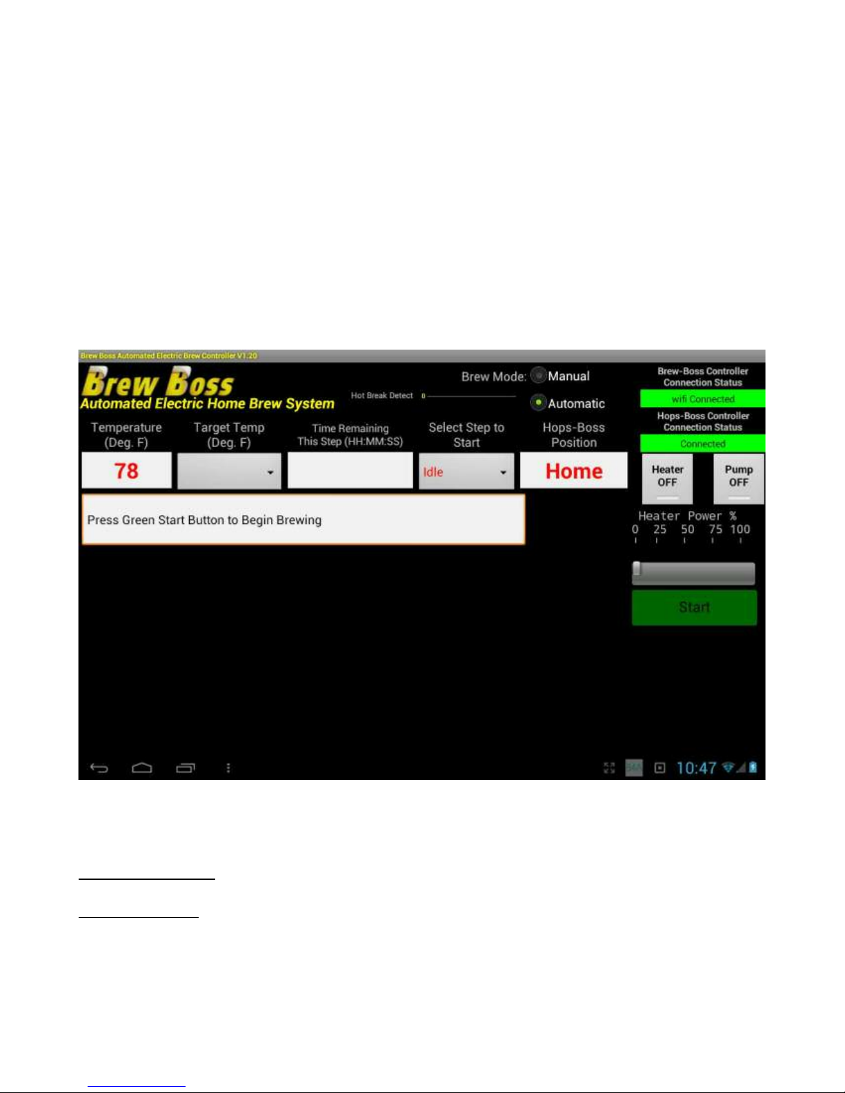
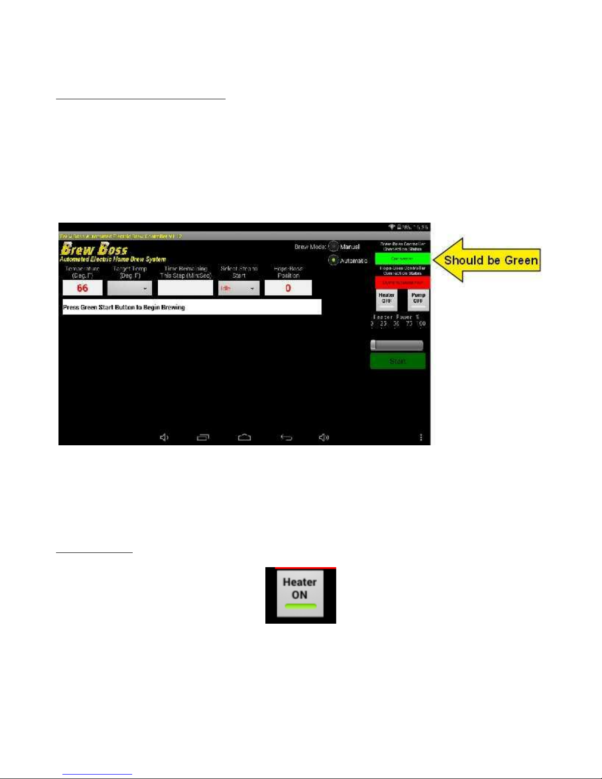
Once you have connected to the Brew-Boss controller, run the Brew-Boss® application. The app
screen shows the status of the connection to the Brew-Boss® controller in the upper right hand corner
of the screen. If you have connected successfully, the Status Bar should turn green and display
“Connected” as indicated in the picture below.
You can test the connection by selecting the menu, other, test alarm. The alarm inside the controller
should sound indicating the tablet is communicating.
3 - System Setup
Select a Location
Select a location for your system. The ideal location is within access to a 30 AMP 240VAC power
panel or outlet (Stove, Dryer, Welder, etc.) for the 240VAC system or within proximity to two separate
Page 5

Brew-Boss® V2.06 Operation Manual
120VAC receptacles on different circuits for the 120 volt systems. It should ideally have a ventilation
system that removes steam vapors and sends them outside. This could be a range hood, etc. You
should have a sturdy work surface such as a counter top, work bench, or table. Basements and garages
are ideal. If you brew outdoors, avoid windy areas or cold temperatures below 50 degrees F. The wind
and/or cold temperatures can greatly affect the ability of the system to maintain temperatures.
Ideally, some type of overhead support such as a floor truss, ceiling truss, etc. for mounting a lifting
device above the kettle is helpful as well. For the COFI version, this is required. Brew-Boss offers a
very nice block and tackle type hoist on the brew-boss.com web site.
Access to a water supply and sink for cleanup nearby is essential.
Brew-Boss® Controller Connections
Page 6

Brew-Boss® V2.06 Operation Manual
Wiring/Power
According to the web site:
www.safeelectricity.org/information-center/library-of-articles/55-home-safety/317-ground-fault-circuit-
interrupters-gfcis
“It is recommended that GFCIs be installed in areas where appliances and power tools are used in
close proximity to water”
The Brew-Boss® system is designed to be as electrically safe as possible considering the fact that it is
being used to heat water and pump water and several amps are involved. To facilitate the use of GFI
breakers and outlets, the various circuit elements must be separately powered. As such, there are
separate power plugs for the 240VAC and 120VAC required by the system.
After receiving your system, you will need to facilitate powering the unit with 220-240VAC and/or
120VAC. The 240VAC system requires a 30 AMP 220-240VAC circuit and a 15 or 20 AMP 120VAC
circuit. The 120VAC system requires two separate 15AMP circuits.
220-240 VAC Circuit
This circuit drives the heater on USA systems and also the pump for systems supplied outside
the USA. The Brew-Boss controller is equipped with a 15 foot long 240 volt power cord
terminated with an L6-30P twist lock plug that is molded onto the cord. It is recommended that
you install an L6-30R receptacle on the GFI circuit you will be running the Brew-Boss syustem
on. If you do not have an L6-30R receptacle and want to use an existing dryer or range outlet,
you can simply cut the molded L6-30P plug off of the cord and install a plug that matches your
outlet (obtain from local home supply or hardware store). The power cable from the controller
has three (3) wires, Black, White, and Green. The White and Black wires get wired to the HOT
prongs of your plug (L1 and L2). The GREEN wire gets wired to the GROUND prong of your
power plug. If you have a 4-wire receptacle, simply do not use the 4th prong, which is the
Neutral wire.
120 VAC Circuit
For the 240VAC system, plug the 3 prong 120VAC plug into a 120VAC outlet. It is
recommended that this outlet be a GFI type as well. This circuit drives the water pump.
For the 120VAC system with dual 1500Watt heater elements, you must locate two 120VAC
outlets in your home that are on different circuits, and route the two power cords to those
outlets. It is recommended that these outlets be GFI type as well. Separate circuits means that
they are serviced by different breakers in your main breaker panel. If you are unfamiliar with
this nomenclature, find someone that understands it or even an electrician to help you locate
acceptable outlets.
Page 7
Brew-Boss® V2.06 Operation Manual
Warning - Shock Hazard!
This is an all electric system. It eliminates the many dangers associated with
gas fired systems, but working with electricity is dangerous. You can be
seriously injured or worse die by electricity. This system requires that you
provide a 240VAC 30 AMP or two 120VAC 15 Amp circuits and the
appropriate power plug. A ground fault interrupter circuit breaker is highly
recommended! If you are not comfortable or not knowledgeable with
electrical wiring please have a certified electrician wire your system.
*** By ordering this product, you accept all liabilities for any and all damages that may occur by your
usage of this equipment. Further you agree to install all equipment in accordance with your local codes
and regulations as required. ***
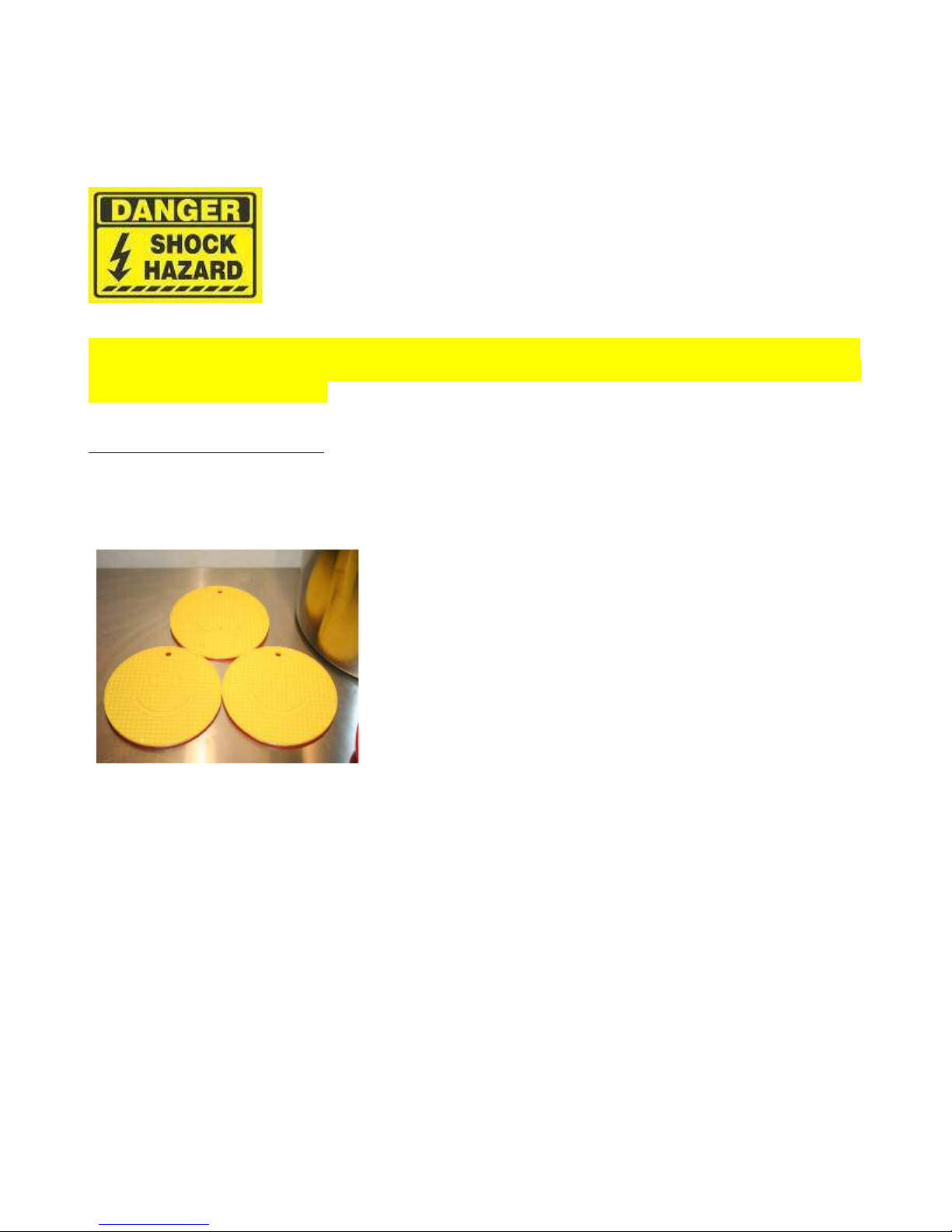
Place Kettle on Work Surface
Place the kettle on a surface that can handle high temperatures. We recommend using silicone trivets
as they prevent thermal losses to the surface and prevent slipping as they are fairly sticky so they keep
the kettle from sliding around. The picture shows the type we are suggesting. Position 3 or 4 of them
in a pattern that assures the kettle is completely supported.
Page 8

Brew-Boss® V2.06 Operation Manual
Install the Heater Element Assembly
The Brew-Boss® heater element assembly is a Tri-Clamp device and needs to be clamped to the Tri-
Clamp ferrule(s) on the lower left side of the kettle using a Tri-Clamp clamp. Install the Red silicone
gasket between the heater and the ferrule on the kettle. Make certain the gasket is centered in the
grooves and does not get pinched while installing the clamp and tightening. Hand tighten the clamp, do
not use tools to tighten the clamp. For 240 Volt 10 gallon systems, install the cap on the spare ferrule
as there is only one heater. For 120 volt systems, install both heater assemblies as described above.
Brew-Boss® Heater Element Assembly
Brew-Boss® Heater Element Assembly Installed in Kettle
Page 9
Brew-Boss® V2.06 Operation Manual
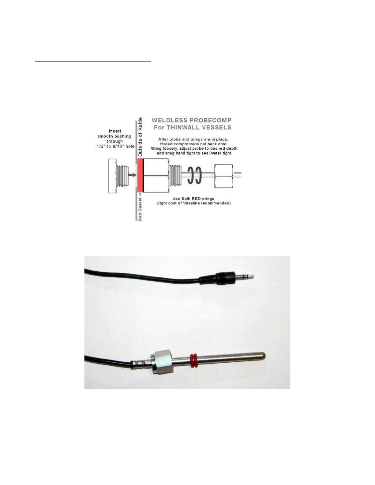
Insert the Digital Temperature Probe
The temperature probe plugs into the controller using a headphone type stereo plug on the right side of
the controller. The system includes a weldless temperature probe coupler that allows direct contact
between the sensor and the water. This provides faster and more accurate temperature control. Install
the weldless temperature probe coupler to the 1/2” diameter hole in the kettle as shown in the drawing
below.
Care must be taken to properly install the temperature sensor. Fist, install the nut and two rubber O-
rings as shown in the picture.
Next, insert the assembly into the coupling on the kettle as shown so that about ¾ – 1 inch protrudes
into the inside of the kettle. Make certain it will not interfere with the COFI infusion filter if you are
using that device. Apply a very small amount of petroleum jelly to the O-rings for lubrication.
Page 10

Brew-Boss® V2.06 Operation Manual
Tighten the nut by hand (never use a wrench)
until it is just tight enough to prevent it from
coming off on it's own. If it leaks, tighten a
little more. Over tightening will damage the
O-rings, so be careful and lean towards too
loose rather than too tight. It is very
important here to make certain the sensor is
not touching any metal of the weldless fitting.
If it touches metal, it will measure the
temperature of the kettle rather than the liquid
(water or wort) in it. The probe should be
insulated by the two o-rings and rest centered
in the hole when viewed from the inside. It
should protrude as far as possible into the
kettle while clearing the COFI filter or false bottom.
If you are seeing readings 5-7 degrees F below actual, you probably have not installed the probe
properly. The sensors supplied with this system are digital and are certified accurate within 1
degree C.
If your system uses a thermowell type temperature sensor housing, simply insert the temperature probe
into the thermowell tube as far as you can get it in so that it bottoms out. The temperature sensor works
best when it is in direct metal to metal contact with the thermowell. It is suggested that thermal grease
or paste be applied to the sensor before it is inserted to improve thermal conduction and thus the
response of the sensor. These thermal products are commonly used to mount heat sinks to computer
processors, etc. and are readily available on the internet or at Radio Shack.
Install Recirculation Plumbing Components
The system includes several stainless steel threaded fittings. It is important to wrap all threads with a
high quality Teflon thread tape. We like “Blue Monster PTFE” tape.
Wrap all male threads in the steps below with 4-6 layers (about 10-12 inches) of tape prior to
assembling all connections. Wrap in the direction shown in the picture so that when threading the
fitting on the tape is forced to wrap onto the thread rather than removed.
Page 11

Brew-Boss® V2.06 Operation Manual
Install Accessory Port
Install the accessory port to the hole on the front top of the kettle. There are two types of accessory
ports, VALUE and DELUXE. The VALUE accessory port has a Camlock nipple on the inside of the
kettle and a barbed nipple on the outside of the kettle.
VALUE Accessory Port Assembly
The DELUXE accessory port has a Camlock nipple on the inside and outside of the kettle.
DELUXE Accessory Port Assembly
Page 12

Brew-Boss® V2.06 Operation Manual
For both accessory port styles, the Camlock fitting shown on the left of both images above is installed
inside the kettle. To install the accessory port, first wrap the threads of the male threaded Camlock
nipple with Teflon tape as described above. Then, install the thin stainless steel washer over the
wrapped threads. Now install the high temperature gasket over the threads being careful not disturb the
Teflon wrap. The nipple will look like the following picture when properly assembled.
Inside Accessory Port Camlock with Teflon Tape, Washer, and Gasket Installed
Next, carefully push the inside accessory port Camlock nipple through the hole on the top of the kettle
from the inside, being careful not to disturb the Teflon wrap.
If a second Stainless Steel thin washer was provided, install that over the threads from the outside.
Now, thread the female nipple onto the wrapped threads. Using two wrenches, tighten the two nipples
together until the gasket just begins to compress visually. The accessory port can remain installed and
typically does not need to be removed. Just make certain when cleaning, to run a small round brush
through the hole to remove any trapped debris.
Install Kettle Valve
Install the valve to the Tri-Clamp to male pipe adapter assuring that the handle will rotate outwards
(away from the kettle) when installed to the kettle. Install the Male Camlock (DELUXE System) or
hose nipple (VALUE System) to the exit side of the valve. Use a Teflon tape on the threaded joints as
described earlier.
Kettle Valve Assembly (shown with DELUXE Camlock nipple)
Page 13

Brew-Boss® V2.06 Operation Manual
Install the valve assembly to the Tri-Clamp ferrule on the bottom front of the kettle (below the Brew-
Boss Logo) using the clear silicone gasket between the valve and the ferrule on the kettle. Make
certain the gasket is centered in the grooves and does not get pinched while installing the clamp and
tightening. Hands tighten the clamp; do not use tools to tighten the clamp.
Kettle Valve Assembly Installed on Kettle (shown with VALUE nipple)
Option: Install Lifting Device
Wet saturated grains can get very heavy (each 9 lbs of grain absorbs about 1 gallon of water) and when
they are hot, can be difficult to work with.
When removing the wet grains, it is desirable to let the grains hang above the kettle for a while to allow
the trapped wort in the grains to drain into the kettle.
If you are using the BIAB mesh bag style system, you'll need a lifting device like the one shown below.
Simply tie the end around the BIAB bag with a slip knot. These locking lifts are nice as they self lock
as you pull them up, so the bag won't drop uncontrolled if you accidentally let go of the rope. We offer
Page 14
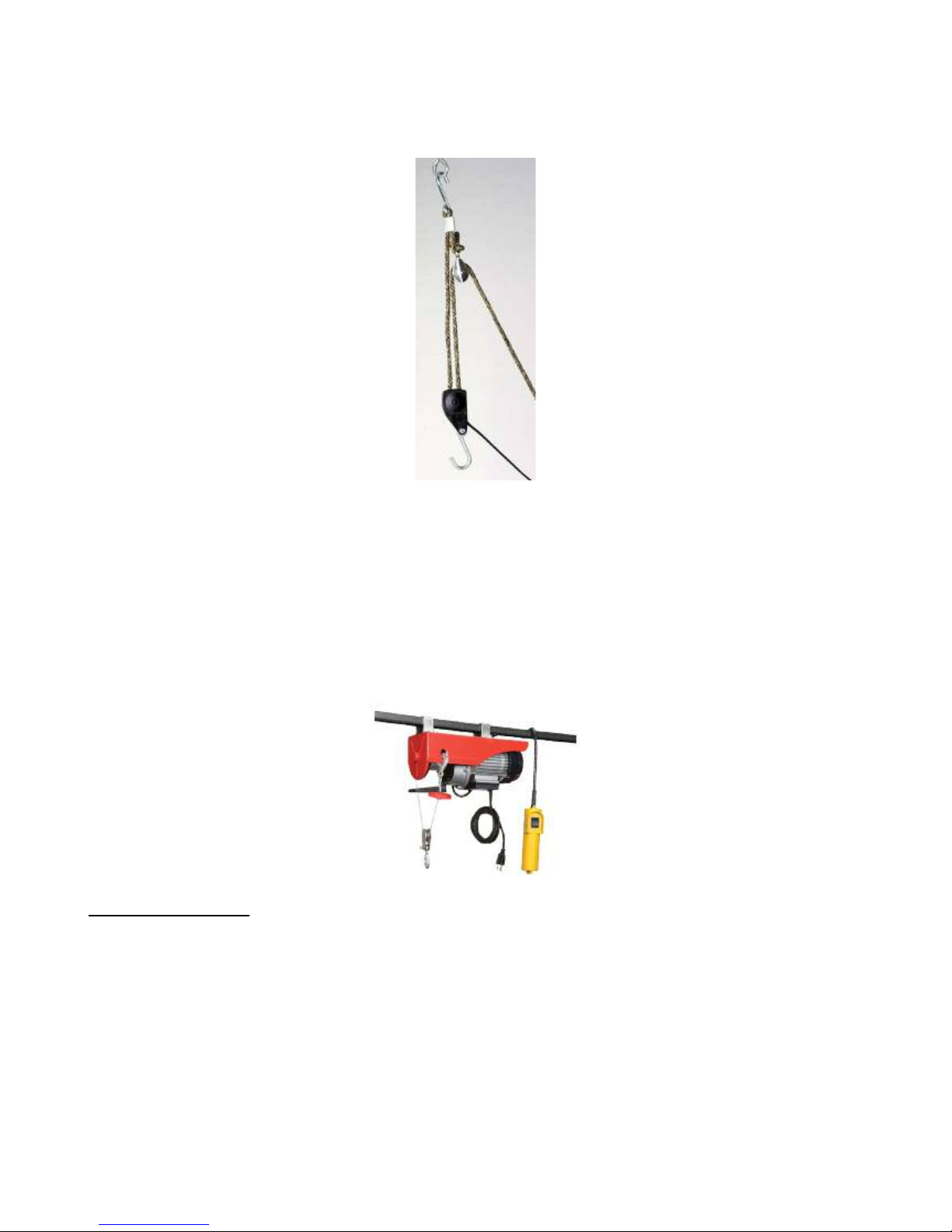
Brew-Boss® V2.06 Operation Manual
these on our web site as well.
Self Locking Lifting Device (Available on Brew-Boss Web Site)
We recommend mounting an eye hook above the kettle to the ceiling, truss, joist, etc. so this can be
utilized.
If you are using the COFI mash infusion filter, we recommend the rope lifting device above, but an
electric hoist is much better! This is what we use. It is a 440 pound capacity hoist and we got ours
from Harbor Freight for $100. When using this, be careful not to hook your COFI filter on the heating
element or the temperature probe. It has a lot of power and can do damage quickly.
Add Water to Kettle
To validate everything is working and that there are no leaks, we need to add water to the kettle. First,
making sure the valve is closed, add enough water so that the water level is just above the temperature
sensor. Check for leaks around the heater element, faucet, and temperature sensor. Make certain
gaskets are positioned properly if you have any leaks.
Note: Never never never ever power the system without enough water in the kettle to cover
the heating element! The element is designed to be submersed and if powered on without being
in water can burn out very quickly. We do not warrant the heating elements for this reason.
Page 15

Brew-Boss® V2.06 Operation Manual
Connect Heating Element to the Controller
The heating element simply plugs into the controller using the L6-30 twist lock connectors. Make sure
that the controller is NOT plugged into the 120 or 240VAC source and the switch on the front of the
controller is in the “OFF” position. It is possible that one could touch one of the metal prongs while
plugging the two connectors together, so make sure the POWER IS OFF! This plug is provided to
make it easy to detach the kettle from the controller so the kettle can be cleaned. Make sure to always
POWER OFF the controller and unplug the controller from the 120 and/or 240VAC source when
unplugging or plugging in the heating element assembly/assemblies.
The heater element should be plugged into the controller before the controller is powered up. Care
should be taken when removing the cord from the heating element to assure that the twist lock is
released by turning counter clockwise before pulling. The cord should come off easily, do not force the
cord off or damage could result to the prongs on the heater element.
Turn the Master Switch On
To turn the master switch on the front of the controller on, move the red lever switch on the front of the
controller to the “ON” position. You can use this switch as an emergency stop switch for the heater if
for some reason you need to turn the heater off quickly, like when you inadvertently turn the heater on
without water! Upon power-up, the LCD on the controller will display a start-up message “B-BOSS
X-X” where the “X-X” is the version number of the firmware installed. If you forgot to plug in the
temperature probe, the controller will beep and warn you that no temperature probe was detected. The
Wi-Fi radio in the controller takes 20-45 seconds to start up. Wait at least this time before trying to
connect to it with the tablet.
Page 16
Brew-Boss® V2.06 Operation Manual
Start the Brew-Boss® Application
After the controller is powered up as described above, make sure you are connected to the Brew-Boss
network as described in Section 2.
After connecting to the Brew-Boss network, you can start the Brew-Boss® app on the Tablet.
The Brew-Boss® App attempts to connect to the controller automatically on start up. The Controller
Connection Status window at the top right side of the screen should turn Green and indicate
“Connected” as shown in the following picture.
Make certain that your system parameters are set up properly as described in Section 6 in this manual.
The temperature shown on the controller LCD should match that shown on the Brew-Boss® App.
Once successfully connected, you can proceed to testing the heater, pump, and Hops Boss®hops feeder
if you have one.
Test the Heater
Test the heater by pressing the Heater Toggle button so that the little green indicator turns on as shown.
The heater power slider bar should change to 100% and the heater power on the LCD display on the
controller should change from 0 to 100.
Page 17

Brew-Boss® V2.06 Operation Manual
Look at the heater element, you should see small bubbles coming off the heater element and most of
the time, hear it heating as well. If it appears the heater is not functioning, confirm that the heater is
plugged into the controller.
Now try dragging the yellow heater power slider to the left with your finger. You should see the power
setting change. Let up on the bar and you should see the corresponding power setting on the LCD
display on the controller.
Install the Pump
The pump is marked with the direction of flow through the pump housing. Water flow is from the
kettle valve, through the pump, and then to the accessory port on the kettle.
Install the stainless steel flow restriction valve on the discharge side of the pump. Use a high quality
Teflon plumbers tape on all threaded joints. Next, install the MALE stainless steel barbed or Camlock
fittings onto the inlet of the pump and outlet port of the flow restriction valve. Do not over tighten,
especially on the plastic body pump.
Page 18
Brew-Boss® V2.06 Operation Manual
Flow Restriction Valve and Nipples Installed on Pump (DELUXE fittings shown on Stainless Pump)
The Brew-Boss® system is supplied with either barbed (VALUE) or Camlock (DELUXE) type quick
connect/disconnect fittings. If you purchased the VALUE system, the silicone brewery hose simply
slips over the barbed nipples on the fittings. No hose clamps are required on the input side of the pump
as there is no pressure inside those hoses. Use the supplied hose clamps for the hoses on the discharge
side of the pump.
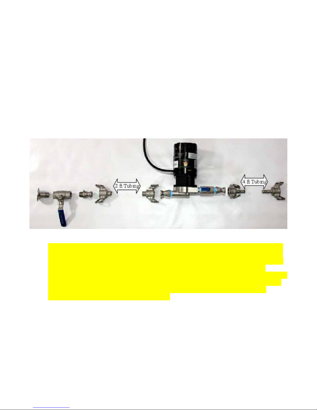
The Brew-Boss® system includes 6 feet of silicon brewery grade tubing. You need to cut this tubing
into two pieces based on your desired setup. We recommend 2 feet between kettle and pump and 4 feet
between pump and kettle, but let you cut it as you desire. If you are using Camlock fittings, you will
need to attach the female camlocks to each of the 4 ends of the tubing you cut. If the Camlocks
provided have differing size nipples, use the nipples with the larger diameter on the pump inlet side.
DELUXE Recirculation Plumbing Hardware Configuration
Note: According to Chugger Pump, the pump should never be run full flow on the discharge.
There should always be some back pressure on the discharge of the pump otherwise the pump
could de-couple and stop pumping. For this reason, always close the flow restriction valve on
the discharge side of the pump slightly to create some back pressure. Of course during
mashing, you adjust the flow restriction valve on the discharge side of the pump to maintain the
proper liquid level in the kettle. With BIAB systems using false bottoms, make certain to stir
your grains often to prevent he pump from creating a vacuum beneath the false bottom,
potentially damaging your kettle or false bottom!
Page 19
Brew-Boss® V2.06 Operation Manual
DELUXE Recirculation Plumbing Hardware Installed
The pump should be located on the same level as the kettle or below the kettle so that at least 12” of
water are above the pump. Connect all the tube ends to the appropriate points as shown in the images
above. The two hose clamps supplied are intended to be installed on hose on the discharge side of the
pump, as that is the high pressure side. No hose clamps are needed on the hose that goes from the
kettle valve to the pump.
Test the Pump
Plug the pump into the pigtail 120 VAC receptacle on the back of the controller. If you purchased the
240 volt pump, you will need to install mating electrical plugs (female on controller and male on pump)
that match your local standards.
Now open the valve and wait for a few seconds for the water to flow into the pump. The pump should
never be run dry, so make sure the valve is open and water has filled the tubing to the pump. The pump
can be screwed down to the work surface or placed on a silicone trivet to keep it from sliding around
and to silence vibrations.
Warning: Never try and run the pump without water in the kettle and the valve on the kettle open.
Running the pump dry can damage it. If you want to test the output, you can plug an electric lamp or
Page 20
Table of contents
Popular Dispenser manuals by other brands

Gourmet Dispensing
Gourmet Dispensing D300 quick start guide

Piusi
Piusi MC BOX B.SMART Installation - use - maintenance

ViscoTec
ViscoTec preeflow eco-DUO 450 Maintenance manual

Desoutter
Desoutter ASD manual

Sprintis
Sprintis E2025 Instruction

Franke
Franke STRATOS STRX635B Installation and operating instructions

Schroeder America
Schroeder America ARIZONA TEA DISPENSER 925 Installation instruction, parts list and configuration guide

SANSTAND
SANSTAND SANTOP user manual

BOWMAN
BOWMAN NC038-0111 manual

Hoshizaki
Hoshizaki DBF-40SAC instruction manual

WEPA
WEPA Satino Assembly instructions

U-Line
U-Line H-1132 Mounting instructions


