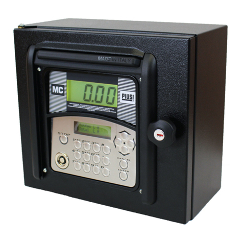
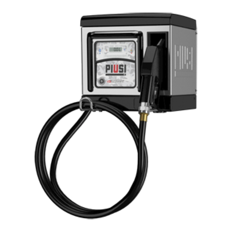
Piusi MC BOX B.SMART Specification sheet

Bulletin M0583 EN_01
Installation, use and maintenance EN
FULL PACK
MC BOX
ETL

2 /4 8
Installation, use and maintenance
M0583
Bulletin M0583 en
ENGLISH

3/124
3 /4 8
EN
This manual is the property of PIUSI S.p.A. Any reproduction, even partial, is forbidden.
translated from Italian
FULL PACK MC BOX etl
INDEX
1 CONFORMITY DECLARATION 4
1.1 ETL DECLARATION OF CONFORMITY 4
1.2 EU CONFORMITY DECLARATION 4
2 GENERAL WARNINGS 4
3 SAFETY INSTRUCTIONS 5
4 FIRST AID REGULATIONS 7
5 SAFETY NORMS 7
6 TRANSPORT, HANDLING AND UNPACKING 8
6.1 DIMENSIONS AND WEIGHTS 8
7 MACHINE AND MANUFACTURER IDENTIFICATION 9
7.1 POSITION OF THE PLATES 9
8 DESCRIPTION OF THE MAIN PARTS 10
9 OPERATION 13
10 TECHNICAL SPECIFICATIONS 15
11 USE 17
11.1 INTENDED USE 17
11.2 NOT INTENDED USE 17
11.3 REASONABLY FORESEEABLE MISUSE 17
12 INSTALLATION 18
12.1 BOX INSTALLATION 18
12.2 HAZARDOUS AREA 19
12.3 ELECTRICAL CONNECTIONS 19
13 INITIAL CONFIGURATION 26
13.1 SWITCHING-ON 26
13.2 CONFIGURATION VIA APP AND WEBAPP 27
13.3 CONTROLLER CONFIGURATION VIA WEBAPP 31
14 DRIVER ACCESS 34
14.1 FIRST DRIVER ACCESS FROM APP 34
14.2 DRIVER - DISPENSING VIA APP 36
14.3 DISPENSING VIA USER KEY (I-BUTTON) 40
15 MAINTENANCE 42
15.1 ROUTINE MAINTENANCE 42
15.2 EXTRAORDINARY MAINTENANCE 42
15.3 CHECK AND REPLACEMENT OF FUSES 42
16 TROUBLESHOOTING 44
16.1 ELECTRICAL/ELECTRONIC CONNECTIONS 44
16.2 PROBLEMS WITH THE SMARTPHONE APP 44
17 FAQ 44
18 SCRAPPING AND DISPOSAL 47
19 EXPLODED VIEW 47
47

4 /4 8
Installation, use and maintenance
M0583
1 CONFORMITY DECLARATION
1.1 ETL DECLARATION OF CONFORMITY
This product is ETL listed for Canada and United States under the UL1238 and CSA 222#142 standards.
1.2 EU CONFORMITY DECLARATION
The undersigned: PIUSI S.p.A.
Via Pacinotti 16/A - Z.I. Rangavino
46029 Suzzara - (MN) - Italy
DECLARES under its own responsibility, that the unit described below:
Description: AUTOMATIC FLUID DISPENSING MANAGEMENT SYSTEM
Model: MC BOX B.SMART
Serial number: refer to the Lot Number indicated on the CE plate affixed to the product
Year of manufacture: refer to the year of production indicated on the CE plate affixed to the product.
conforms to the legal regulations that transpose the following directives:
- Low Voltage Directive 2014/35/EU
- Electromagnetic Compatibility Directive 2014/30/EU
- ROHS II Directive 2011/65/EU
- RED Directive 2014/53/EU
The documentation is at the disposal of the relevant authority upon justified request at PIUSI S.p.A. or
request via e-mail: doc_tec@piusi.com The party authorised to compose the technical file and draw up
the declaration is Otto Varini in his capacity as legal representative.
Suzzara, 01/07/2020
Otto Varini
legal representative.
2 GENERAL WARNINGS
IMPORTANT
INFORMATION
For operators’ safety and to prevent any damage, the instruction manual
must be fully read and understood before carrying out any operation.
Symbols
used in the
manual
The following symbols will be used in the manual to highlight particularly
important instructions, warnings and information.
WARNING
This symbol indicates safety regulations for the operators and/or any
persons at risk.
ATTENTION
This symbol indicates the possibility of damage to the unit and/or its
components.
NOTE
This symbol indicates useful information.
Storage of the
manual
This manual must be whole and legible in its entirety. The end user and
specialist technicians authorised for installation and maintenance must be
able to read it at any time.
Reproduction
rights
All reproduction rights of this manual are reserved to Piusi S.p.A.
The text cannot be used in other printed publications without written authorisation
from Piusi S.p.A.
© Piusi S.p.A.
THIS MANUAL BELONGS TO PIUSI S.p.A.
THE REPRODUCTION OF ALL OR PARTS IS PROHIBITED.
This manual belongs to Piusi S.p.A., the exclusive holder of all rights envisaged by the
relevant laws, including by way of example copyright law. All rights according to such law
are reserved to Piusi S.p.A.: the reproduction of all or parts of this manual, its publication,
alteration, transcription, disclosure to the public, distribution, sale in any form, translation
and/or processing, loan, and any other activity reserved by law to Piusi S.p.A.

5/124
5 /4 8
EN
This manual is the property of PIUSI S.p.A. Any reproduction, even partial, is forbidden.
translated from Italian
FULL PACK MC BOX etl
3 SAFETY INSTRUCTIONS
WARNING
Electrical supply -
preliminary checks
for the installation
Completely avoid contact between the electrical supply and the liquid
to be pumped.
Inspection and
maintenance
operations
Before any inspection or maintenance, cut off the POWER SUPPLY
FIRE AND
EXPLOSION
When flammable
liquids are present
in the work area,
flammable vapours
may be present
and may cause fire
or explosion during
station use.
To prevent fire and explosion risks:
Use the station only in ventilated areas
Keep the work area free of scraps, including scraps and solvent or petrol
tanks.
Do not plug or unplug or operate the switch in the presence of flammable
vapours.
All devices in the work area must be grounded.
Interrupt immediately any action if there are sparks or shocks. Do not use
the station until you have identified and resolved the problem.
Keep a fire-extinguisher in good working order close to the working area.
ELECTRICAL
SHOCK
Electrocution or
death
FThis station must be grounded. Improper installation or use of the station
may result in danger of electric shock.
Switch off and unplug the power cord after use.
Connect only to grounded sockets.
Use only grounded cables in accordance with the applicable regulations.
Unsuitable extension leads may be dangerous.
Make sure that the plug and socket of the extension cords are intact.
Unsuitable extension leads may be dangerous.
In outdoor use, use only extensions suitable for the specific use, according
to the regulations in force.
The plug and socket must be connected far from water.
Do not expose to rain. Install in a sheltered location.
Never touch the plug or the socket with wet hands.
Do not turn the dispensing system on if the supply connection cable,
WARNING parts of the unit, e.g. the suction/delivery pipe, the nozzle
or the safety devices are damaged. Replace the damaged pipe immediately
before use.
Before each use, check that the mains connection cable and the plug are
not damaged. If damaged, have the cable and plug replaced by qualified
personnel
.
The plug and socket must be connected far from water.
Outdoors, use only authorised extension leads for which this use is
envisaged with an adequate wire diameter in accordance with the
regulations in force.
As a general rule of electrical safety it is always recommended to power the
device by protecting the line with:
- circuit breaker/disconnector with a current rating suitable for the power
line
- 30 mA residual current device
The electrical connection must have a ground fault current interrupter
(GFCI).
Installation operations are carried out with the box open and the electrical
contacts accessible. All these operations must be carried out with the unit
isolated from the mains in order to avoid hazards of electrocution!
6 /4 8
Installation, use and maintenance
M0583
IMPROPER USE
OF THE UNIT
Improper use of the
device can cause
serious damage or
death.
!Do not operate the unit when tired or under the influence of drugs or
alcohol.
Do not leave the work area while the unit is on and operating.
Turn off the unit when not in use.
Do not alter or modify the unit. Alterations or modifications to the unit
may invalidate its type-approval and result in dangers to safety.
Arrange the hose and the power cables always far from transit areas,
sharp edges, moving parts and hot surfaces.
Do not twist the hose or use a stronger hose.
Keep children and animals far from the work area
Observe all applicable safety regulations.
Do not exceed the maximum working pressure or temperature of the
component with the lowest system rating.
See the technical specifications in all machine manuals.
Use liquids and solvents that are compatible with the wet parts of the
unit. See the technical specifications in all machine manuals. Read
the manufacturer's warnings for liquids and solvents. To obtain more
information about the material, request the Safety Data Sheet (MSDS)
from your distributor or dealer.
Check the unit every day. Repair or replace worn or damaged parts
immediately with original manufacturer's spare parts only.
Make sure that the unit is classified and approved in accordance with the
regulations for the environment in which it is used.
Use only the unit for its intended purpose. Contact your distributor for
more information.
Keep hoses and cables away from transit areas, edges, moving parts and
hot surfaces.
Do not bend or bend the hoses too much or use the hoses to pull the unit.
DANGER OF
BURNS
To avoid severe burns, do not touch liquids or equipment
Danger of smoke
and toxic fluids.
For problems deriving from the product handled with eyes, skin, inhalation
and ingestion, refer to the safety data sheet of the fluid used.
Store treated liquids in suitable containers and in compliance with
applicable regulations.
Prolonged contact with the product handled may cause skin irritation;
always use protective gloves when dispensing.

7/124
7 /4 8
EN
This manual is the property of PIUSI S.p.A. Any reproduction, even partial, is forbidden.
translated from Italian
FULL PACK MC BOX etl
FIRE AND
EXPLOSION
If it is necessary
to dispense in
areas classified
as hazardous for
explosion, it is
forbidden to use
the smartphone
less than 30 cm
away from the
fluid at the time of
dispensing.
The PIUSI B-SMART product has been conceived to be used together
with the user's mobile phone only and exclusively for the operations of
connection, authentication and connection of the user's device to the fuel
dispenser in order to perform remotely certain operations described in this
manual.
If the PIUSI B-SMART product is used to refill petrol or other fuel or liquid
that emits flammable vapours or in any case creates potentially explosive
atmospheres according to the current ATEX regulations (Directive
2014/34/EU and relative applicable national implementing provisions,
including any later amendment or additions), the use of the mobile phone
while dispensing and in any case within any zone classified for ATEX
purposes in accordance with the regulations in force is strictly prohibited,
except in the case where the unit is regularly ATEX certified and authorised
for use in the relevant area. The mobile phone must therefore remain
outside this area or be switched off.
The use of the mobile phone by the user when refilling the vehicle with
other non-flammable liquids is in any case strongly discouraged as it can
cause distractions that can be dangerous.
PIUSI disclaims any and all liability in the event of damage to the person
or property of the user or third parties resulting from failure to comply with
the above warnings and / or any other negligent, reckless or imperishable
behaviour of the user.
4 FIRST AID REGULATIONS
Persons subject-
ed to electrical
discharge
Disconnect the supply, or use a dry insulator for protection when moving
the victim far away from any lead. Avoid touching the victim with bare
hands until they are far away from any lead. Request the assistance of
trained, qualified staff immediately. Never operate switches with wet
hands.
NO SMOKING Do not smoke near the dispenser and do not use the pump near open
flames.
5 SAFETY NORMS
BASIC
CHARACTER-
ISTICS OF THE
PROTECTIVE
EQUIPMENT
Wear protective equipment that is:
• suitable for the operations to be carried out
• resistant to the products used for cleaning.
PERSONAL
PROTECTIVE
EQUIPMENT TO
BE WORN
Safety shoes;
Close-fitting clothing;
Protective gloves;
Safety goggles;
OTHER
EQUIPMENT
Instruction manual.

8 /4 8
Installation, use and maintenance
M0583
6 TRANSPORT, HANDLING AND UNPACKING
During machine inactivity, both packed or unpacked, it should be stored
in an area protected against weather agents (rain, moisture, sun, etc...)
and dust.
To open the cardboard packaging, use scissors or a cutter, taking care not
to damage the system. Fully open the packaging and grasp the MC BOX
B.SMART so that it can be positioned afterwards.
The packaging elements (cardboard, wood, cellophane, etc...) must be
placed in the suitable containers and not left in the environment or within
children easy reach as they are potentially harmful. Disposal should be
performed in compliance with the standards in force in the utilisation
country.
Make sure the unit is integer controlling all parts for possible damage that
could hinder safety and functionality. In case of doubt, do not start up and
contact the manufacturer's technical service.
The packaging shall bear the following indications:
- label showing the information for the equipment (model, weight, etc.).
SB_D_001
6.1 DIMENSIONS AND WEIGHTS
MODEL TOTAL
WEIGHT
(kg)
PACKAGING
DIMENSIONS (mm)
171.1
286
267
MC BOX
B.SMART 5.3 480 x 370 x 265
PEDESTAL
KIT 15 -

9/124
9 /4 8
EN
This manual is the property of PIUSI S.p.A. Any reproduction, even partial, is forbidden.
translated from Italian
FULL PACK MC BOX etl
7 MACHINE AND MANUFACTURER IDENTIFICATION
The MC BOX B.SMART stations are equipped with an identification plate
attached to the frame:
- Model
- Serial number /
Year of manufacture
- Technical data
- CE marking
- Manual code
WARNING Before installation, always check that the dispensing system model
is correct and suitable for the supply currently available (Voltage /
Frequency).
7.1 POSITION OF THE PLATES
Some stickers and/or plates are applied to the MC BOX B.SMART to
indicate the most relevant information to the operator. It is necessary to
check that these do not deteriorate or detach over time.
NOTE Should this occur, please contact our customer assistance office so
that we can send you copies of the spoilt or missing plates/labels for
reapplication where originally provided.
The following labels are present:
1 CE plate with technical data
F00599020
MC BOX 120V B.SMART
ETL 10 ACCESS
1234567
2 Corner label plate applied on the box
MADE in ITALY
ZONE “0”
ZONE “1”
ZONE “2”
3 Adhesive for prohibiting the use of smartphones
in the vicinity of the dispenser during dispensing
After activation of the dispensing, during refilling
operations, do not use your smartphone less than
30cm from the dispenser.
APPLICATION CHARGED TO THE INSTALLER
To be applied in case MC BOX B.SMART is installed
near a classified area
MCBox ETL-
4 - Product warranty label

10 /4 8
Installation, use and maintenance
M0583
MCBox ETL-
8 DESCRIPTION OF THE MAIN PARTS
FOREWORD B.SMART is an electronic system for controlling the dispensing of fluids via
smartphone.
The control system consists of:
An electronic controller
equipped with a BlueTooth interface (BLE 4.0 and later), a display and an
interface LED that controls a dispensing pump
An APP
installed on a smartphone equipped with an Android operating system or
Apple IoS
A WebAPP
namely an internet portal accessible from any PC or Tablet connected to the
internet from which the entire site can be monitored
SYSTEM FUNCTIONS • site configuration, acquisition and management of refillings,
management of refilling fuel dispensers, management of drivers,
vehicles and detailed reporting of the dispensings via WebAPP
accessible from any PC/Tablet, using your credentials
• Fuel dispensing using the dedicated APP: PIUSI APP, downloadable
only for smartphones from Play Store and App Store, which connects to
the fuel dispenser / controller via BLE connection
• Fuel dispensing using the dedicated APP also in areas without 3/4G
coverage and Wi-Fi
• Dispensing via iButton associated with the individual driver
• Possibility to remotely manage sites far from the company headquarters

11/124
11 /4 8
EN
This manual is the property of PIUSI S.p.A. Any reproduction, even partial, is forbidden.
translated from Italian
FULL PACK MC BOX etl
As can be seen from the descriptive diagram on page 12, an example of the
basic structure of the system is shown, which shows the possibility of:
• manage an engine output
• monitor the level of 1 tank as needed, even if a tank is shared by pumps
connected to different control units
• manage multiple control units simultaneously, within the same system
For more specific details on how to connect and communicate between the
control units, please refer to the manual contained in the WebApp of
plant management.
COMPATIBILITY
WITH OPERATING
SYSTEMS
The system is compatible with the following iOS versions:
• iOS10
• iOS11
• iOS12 and the following
The system is compatible with the following Android versions:
• 5.0 - 5.1
• 6.0
• 7.0 - 7.1
• 8.0
• 9.0 and the following
EQUIPMENT AND
CHARACTERISTICS
The system consists of several devices:
BOX composed of an electronic controller to manage fuel dispensing, equipped
with:
• Numeric display
• Reader for iButton
• BLE 4.0 connection (or following)
• Status sensors for: level alarms, flow meters, positioning of the
dispensing nozzle
• Pump on/off control
CLOUD Where there is the database to store the configurations of the site and the
dispenser, the drivers, the license plates of the vehicles and all the dispensings
WebApp Web interface used by the site manager. It has various functions: it monitors
the dispensings (from whom they were made, when, in which controller),
creates/eliminates users from the site, adds/removes controllers/fuel
dispensers from the site. The only external device the WebApp connects to is
a USB reader for iButton
APP It makes several operations:
• It manages two types of users: driver and manager
• It sends commands to the controller and receive answers, the commands
are used to perform: dispensing, calibration, updating the firmware of
the controller, downloading updates of the controller configuration,
managing the drivers or loading in the cloud the dispensings in the
controller

12 /4 8
Installation, use and maintenance
M0583
iBuon WebApp
APP
iBuon
Cloud
Database
MCbox ETL B.SMART n
iBuon
MCbox ETL B.SMART 1

13/124
13 /4 8
EN
This manual is the property of PIUSI S.p.A. Any reproduction, even partial, is forbidden.
translated from Italian
FULL PACK MC BOX etl
9 OPERATION
The controller is powered by 100/240 V ac, it drives a motor that can absorb a maximum current of
15 A. It has a 4-character backlit display, iButton reader, blue led for Bluetooth connection and red
led for warning/alarm:
• NOT FOR RESALE • NICHT EICHFÄHIG • PARA UTILISACION EXCLUSIVA DEL USUARIO •
INTERDIT POUR TOUTES TRANSACTIONS COMMERCIALES OU FISCALES • APPARECCHIO
NON IDONEO ALLA MISURAZIONE DI PRODOTTI PER LA VENDITA AL PUBBLICO • NE È
VIETATO L’USO IN RAPPORTO A TERZI • CIRC. MIN. N°67 DEL 25/07/1996 •
MADE in ITALY
RED LED:
when on, a display coding
is shown which indicates a
series of warnings or alarms.
See error coding table.
DISPLAY
Backlighting on:
the driver or manager has been authenticated via smartphone or the driv-
er has been authenticated via iButton.
The display shows:
• the version of the installed firmware,
• the value of the dispensing,
• the time,
• warning or alarm code when the red LED is on,
• the boot status for the firmware update,
• the percentage of firmware transferred.
BLUE LED:
when lit, it
indicates that
a device is
connected in
Bluetooth
IBUTTON reader
NOTE Red LED on - It switches on due to several factors, each time the LED lights
up the display shows a code indicated by a letter A and by an incremental
number. Whenever the led is on, it is not possible to dispense.
Below are the possible coded errors, with their respective resolution methods:
Coding Description Explanation/Solution
C1 WARNING_MASTER_PUMP_
GROUPA_LEVEL1_CONTACT
Contact 1 associated with pump A of the main controller is
active: red LED flashing.
C2 WARNING_MASTER_PUMP_
GROUPA_LEVEL2_CONTACT
Contact 2 associated with pump A of the main controller
is active: red LED flashing.
C3 WARNING_MASTER_PUMP_
GROUPA_THR1
The tank associated with pump A of the main controller
has reached the level 1 threshold: red LED flashing.
C4 WARNING_MASTER_PUMP_
GROUPA_THR2
The tank associated with pump A of the main controller
has reached the level 2 threshold: red LED flashing.
C9 WARNING_SLAVE_PUMP_
GROUPA_LEVEL1_CONTACT
Contact 1 associated with pump A of the secondary con-
troller is active: red LED flashing.
C10 WARNING_SLAVE_PUMP_
GROUPA_LEVEL2_CONTACT
Contact 2 associated with pump A of the secondary con-
troller is active: red LED flashing.
C11 WARNING_SLAVE_PUMP_
GROUPA_THR1
The tank associated with pump A of the main controller
has reached the level 1 threshold: red LED flashing.
C12 WARNING_SLAVE_PUMP_
GROUPA_THR2
The tank associated with pump A of the secondary con-
troller has reached the level 2 threshold: red LED flashing.

14 /4 8
Installation, use and maintenance
M0583
C17 WARNING_MASTER_PUMP_
GROUPA_PROBE_OCIO
Fault detected on the level sensors connection line. (The
system allows manual dispensing).
C19 WARNING_MASTER_SLAVE_
GROUPA_PROBE_OCIO
Fault detected on the level sensors connection line. (The
system allows manual dispensing).
C25 WARNING_CANBUS_COM Fault detected on the connection line between controllers.
The system behaves as for probe alarms, allowing manual
dispensing.
A1 ALARM_MASTER_PUMP_
GROUPA_LEVEL1_CONTACT
Contact 1 associated with pump A of the main controller is
active: red LED on (not flashing). Dispensing not possible.
A2 ALARM_MASTER_PUMP_
GROUPA_LEVEL2_CONTACT
Contact 2 associated with pump A of the main controller
is active: red LED on (not flashing). Dispensing not pos-
sible.
A3 ALARM_MASTER_PUMP_
GROUPA_THR1
The tank associated with pump A of the main controller
has reached the level 1 threshold: red LED on (not flash-
ing). Dispensing not possible.
A4 ALARM_MASTER_PUMP_
GROUPA_THR2
The tank associated with pump A of the main controller
has reached the level 2 threshold: red LED on (not flash-
ing). Dispensing not possible.
A9 ALARM_SLAVE_PUMP_GROU-
PA_LEVEL1_CONTACT
Contact 1 associated with pump A of the secondary con-
troller is active: red LED on (not flashing). Dispensing not
possible.
A10 ALARM_SLAVE_PUMP_GROU-
PA_LEVEL2_CONTACT
Contact 2 associated with pump A of the secondary con-
troller is active: red LED on (not flashing). Dispensing not
possible.
A11 ALARM_SLAVE_PUMP_GROU-
PA_LEVEL1_THR1
The tank associated with pump A of the main controller
has reached the level 1 threshold: red LED on (not flash-
ing). Dispensing not possible.
A12 ALARM_SLAVE_PUMP_GROU-
PA_LEVEL1_THR2
The tank associated with pump A of the secondary con-
troller has reached the level 2 threshold: red LED on (not
flashing). Dispensing not possible.
A28 ALARM_BUFFER_FULL The dispensing buffer is full. All the dispensing operations
stored in the controller must be uploaded to the cloud.
A29 ALARM_INACTIVE_PUMP No pumps are active.
(Check system configuration on WebApp)
A30 ALARM_RTC_RESET The time has been lost. The current time must be uploaded
to the controller via a smartphone.
A31 ALARM_RTC_FAULT Time synchronization not possible.
(Contact the Service Department).
A32 ALARM_SOFT_MEMORY_
DATA_FAULT(Cumulative)
Corrupted memory (data can be reset from WebApp
backup).
A33 ALARM_HARD_MEMORY_
DATA_FAULT(Cumulative)
Corrupted memory (data can be reset from WebApp
backup).
A34 ALARM_VERY_HARD_MEMO-
RY_DATA_FAULT(Cumulative)
Damaged memory (contact the Service Department).
With regard to the warning/alarm logics, it should be noted that one or more pump units can be
connected to the same tank, or share common level contacts as outlined in the paragraph describing
the system.
In these situations, warnings and alarms from one controller will be propagated to the other control-
lers sharing the same resource.
For more specific details on modes of connection and communication between controllers, please
refer to the manual found in the system management WebApp.

15/124
15 /4 8
EN
This manual is the property of PIUSI S.p.A. Any reproduction, even partial, is forbidden.
translated from Italian
FULL PACK MC BOX etl
10 TECHNICAL SPECIFICATIONS
INTENDED USE Implementation of a system for the dispensing and control of fluids for
private use not subject to special regulations such as ATEX for potentially
explosive environments.
WARNING DO NOT INSTALL MC BOX B.SMART IN ENVIRONMENTS CLASSIFIED
AS POTENTIALLY EXPLOSIVE IN ACCORDANCE WITH ATEX
REGULATIONS.
MAXIMUM
VARIATIONS
IN
ELECTRICAL
PARAMETERS
The motors in the dispensers accept maximum variations:
of supply voltage by +/- 5%
and maximum frequency variations of +/- 2%
SEE TECHNICAL SPECIFICATIONS TABLE BELOW
WARNING
BEFORE INSTALLATION, ALWAYS CHECK THAT your MODEL IS
CORRECT AND SUITABLE FOR THE SUPPLY EFFECTIVELY AVAILABLE
(VOLTAGE / FREQUENCY).
Signal Standard
conditions
Limits Notes
Power supply
input
100-240 V ac Maximum power
absorbed in stand-by
of 5W
The electronic board is equipped with
a switching technology power supply
that allows a wide range of voltages
and frequencies and therefore makes
the equipment robust for the high
fluctuations of voltage or frequency
present on the power distribution
mains in many areas of the world
Motor piloting
output
100-240 V ac Imax 15 A
Electronic key
interface
YELLOW key
(iButton): Enabling
input by PIUSI
electronic key
Through a software
procedure, the yellow
keys of the drivers are
registered on the PC
and then these drivers
are enabled on one
or more dispensing
stations
You can configure whether or not
such a key is present
Nozzle contact
input
(only for
versions where
available)
Clean contact or
Open Collector
(NPN) electronic
signal
About 250 uA at 5 V
dc will be supplied on
the clean contact (or
on the open collector)
It is possible to configure whether or
not this contact is present, and it is
also possible to configure the type
of signal (normally open or normally
closed)
Pulser IN input
Free contact or
Open Collector
(NPN) electronic
signal
About 250 uA at 5 V
dc will be supplied on
the clean contact (or
on the open collector)
The input signal can
have a maximum
frequency of 300
Hz with a Duty Cycle
between 20% and
80%
The input signal can have a maximum
frequency of 300 Hz with a Duty
Cycle between 20% and 80%

16 /4 8
Installation, use and maintenance
M0583
Level 1 contact
input
(only for
versions
where
available)
Clean contact or
Open Collector
(NPN) electronic
signal If it is
necessary to supply
a level sensor, 24 V
dc are also available
on the terminal. The
maximum current
available to the
sensor for its power
supply is 25 mA
About 1 mA at 5 V dc
will be supplied on the
clean contact (or on
the open collector)
It is possible to configure whether or
not this signal is present, and it is also
possible to configure the type of signal
(normally open or normally closed
for versions where provided) Finally,
it is possible to choose the action to
be taken by the controller when it
receives this signal: it can only give an
alarm on the display or it can totally
inhibit other dispensings if the Pump
Block is set
Level 2 contact
input
(only for
versions
where
available)
Clean contact or
Open Collector
(NPN) electronic
signal If it is
necessary to supply
a level sensor, 24 V
dc are also available
on the terminal. The
maximum current
available to the
sensor for its power
supply is 25 mA
About 250 uA at 5 V
dc will be supplied on
the clean contact (or
on the open collector)
It is possible to configure whether or
not this signal is present, and it is also
possible to configure the type of signal
(normally open or normally closed
for versions where provided) Finally,
it is possible to choose the action to
be taken by the controller when it
receives this signal: it can only give an
alarm on the display or it can totally
inhibit other dispensings if the Pump
Block is set
24 V dc
auxiliary
power supply
output
24 V dc auxiliary
output to supply
external electronic
devices
Imax = 25 mA The device to be supplied must not
absorb more than 25 mA with 24 Vdc
power supply. Typically it could be a
level sensor
Fuses
F1 (V ac power input) 800 mA T (delayed)
F2 (motor output) 20 A T (delayed)
F3 (AC/DC output) 800 mA T (delayed)
IP protection
degree
IP 55
Operating
temperature
From -10° C to +40°C
Storage
temperature
From -20° C to +60°C
Humidity
< 90%
Wiring
distances
Max. pulser
distance 15 m
Max. level sensor
distance 100 m
Counting and
display limits
The floating point sequence: 0.00 -> 99.99 -> 999.9 -> 9999
The maximum quantity that can be dispensed is 9999 units regardless of the unit of
measurement set litres/gallons/pints
0.00 9,999 99.99 999.9 9999
PRESET: Presettable
maximum quantity
9999 litres/gallons/
pints
Memories
The electronic controller can store:
- Up to 500 users
- Up to 500 dispensings

17/124
17 /4 8
EN
This manual is the property of PIUSI S.p.A. Any reproduction, even partial, is forbidden.
translated from Italian
FULL PACK MC BOX etl
11 USE
11.1 INTENDED USE
MC BOX B.SMART IS DESIGNED TO MANAGE DISPENSING FOR SEVER-
AL REFILLING STATIONS FOR PRIVATE USE.
DEDICATED APP AND WEB APP MAKE IT EASY TO USE, BY RETURNING
A SUMMARY OF ALL DISPENSINGS.
WARNING
Use ambient
conditions
Ambient temperature: min. -20°C / max. +60°C
Relative humidity: max. 90%
The limit temperatures indicated apply to the pump components and must
be observed to avoid possible damage or malfunction.
11.2 NOT INTENDED USE
WARNING
Flammable
liquids and
explosive
atmospheres
MC BOX B.SMART HAS NOT BEEN DESIGNED IN ACCORDANCE WITH
ATEX REGULATIONS OR TO OPERATE IN ENVIRONMENTS WITH A
POTENTIALLY EXPLOSIVE ATMOSPHERE.
DO NOT INSTALL MC BOX B.SMART IN POTENTIALLY EXPLOSIVE
LOCATIONS.
The system was not designed for the dispensing of diesel, petrol, flammable
liquids with flash point <55°C/131°F, or for operation in environments with a
potentially explosive atmosphere.
Use in the conditions indicated above is therefore prohibited.
WARNING
Not intended
use
Use of the system for purposes other than those intended is strictly
prohibited. Any use other than that for which the system was designed
and described in this manual is considered “IMPROPER USE”, for which
Piusi S.p.A. accepts no responsibility in case of damage to property,
persons, animals or the system itself.
11.3 REASONABLY FORESEEABLE MISUSE
The smartphone is an indispensable tool for MCbox B.SMART to set up and record the dispensings
managed by the system, but it is forbidden to use it when dispensing near the dispenser.
WARNING It is absolutely forbidden to use the mobile phone when dispensing petrol
or other fuel or liquid that emits flammable vapours or in any case creates
potentially explosive atmospheres; in any case within any area classified
for ATEX purposes in accordance with the regulations in force, except in
the case where the device is regularly ATEX-certified and authorised for
use in the relevant area. The mobile phone must therefore remain outside
this area or be switched off.
WARNING Use your smartphone only and exclusively to connect, authenticate and
pair from your device to the dispenser. When refilling the vehicle, even
with non-flammable liquids, the use of the telephone is in any case
strongly discouraged as it can cause distractions that can be dangerous.

18 /4 8
Installation, use and maintenance
M0583
12 INSTALLATION
12.1 BOX INSTALLATION
FOREWORD MC BOX B.SMART can be installed outdoors However, it is advisable to
shelter it under a canopy to ensure a longer life and provide more comfort
during use in bad weather.
The installation must be carried out by specialised personnel according to
the instructions in this chapter.
ATTENTION
Staff
authorised for
installation
All installation operations must be performed only by competent and
authorised staff, who must:
- Install the system in a dry, well-ventilated place;
- Properly install the accessories necessary for the correct operation of the
unit.
- Use solely the accessories provided with the system.
WARNING THE UNIT IS FOR PROFESSIONAL USE ONLY.
The use of unsuitable accessories not provided with the system is strictly
prohibited. Piusi S.p.A. accepts no responsibility for harm to persons,
property or the environment due to failure to observe this instruction.
MC BOX B.SMART must be installed in an adequately lit location, in
compliance with the regulations in force.
MC BOX B.SMART has been designed to be used in a dry place. If it is
installed outdoors, provide adequate protective covering.
MCbox B-SMART can be installed on the wall or on a pedestal.
For wall mounting, it will be necessary to have a nr. 4 M8 screws.
For pedestal mounting, use no. 4 M6 screws.
Below are the diagrams with the center distances of the holes for a precise
installation.
The pedestal is a Piusi accessory not included in the MCbox B-SMART sup-
ply.
WALL MOUNTING
232.4
286
Ø9
4x
15070.2
262
171.1
157.25

19/124
19 /4 8
EN
This manual is the property of PIUSI S.p.A. Any reproduction, even partial, is forbidden.
translated from Italian
FULL PACK MC BOX etl
MOUNTING ON A
PEDESTAL
7522.8
236
286
Ø94x
optional
WARNING PROVIDE FOR THE INSTALLATION OF MCBOX B-SMART IN AREAS
WHERE THERE IS NO RISK OF EXPLOSION
12.2 HAZARDOUS AREA
Any fuel dispenser is a hazardous area as defined in the National Electrical Code. Installation must be
in accordance with the following:
¦ National Electrical Code (NFPA No. 70);
¦ Automotive and Marine Service Station Code (NFPA No. 30A).
WARNING The installer is responsible to investigate and follow any local codes.
MC BOX Bsmart ETL is listed for use in a non-classified area. All of the
equipment must be installed outside of the hazardous areas.
NOTE Local codes may dictate specific installation requirements. Installation is
subject to approval by the local authority having jurisdiction at the site.
12.3 ELECTRICAL CONNECTIONS
ELECTRICAL
CONNECTIONS
The electrical connections must be carried out in a workmanlike manner by
specialised personnel, in full compliance with the regulations in force in the
country of installation and with the instructions in the electrical diagrams in
this manual.
WARNING The MC BOX B.SMART Electronic Panel is NOT equipped with circuit
breakers; it is therefore essential to install upstream MC BOX B.SMART
an electrical power supply panel equipped with a circuit breaker /
disconnector with a current rating suitable for the electrical line and a
differential switch suitable for the type of electrical load.
Otherwise, provide for a quick disconnection system such as a socket/plug
connection to be used in the event of faults.
WARNING Before accessing the electrical parts, make sure that you have
disconnected all the main switches that energize the unit.

20 /4 8
Installation, use and maintenance
M0583
The operations required for a correct wiring are described below:
• Opening the rear cover of the controller
• Power supply connector
• Pump connector
• Connector for: 24 V dc service power supply, nozzle contact, pulser,
level 1 and 2 contact
• Controller PG connection
• Closing the rear cover of the controller
• ocio connection on RS485 (if used)
• interface connection with other canbus control units
OPENING THE
REAR COVER
OF THE
CONTROLLER
Loosen all 8 screws of the rear cover of the controller to access the
compartment of the electronic boards
CABLE GLAND
CONNECTION
The cable glands to be used for the various signals are indicated in order
to obtain an optimised cable route inside the controller
Table of contents
Other Piusi Dispenser manuals

Piusi
Piusi SB325 User manual

Piusi
Piusi SB325M Use and care manual

Piusi
Piusi SUZZARABLUE PRO User manual

Piusi
Piusi MC BOX 1.5 ETL User manual

Piusi
Piusi CUBE B.SMART Quick start guide

Piusi
Piusi PW-LAN User manual

Piusi
Piusi Cube 56/33 Installation and operating instructions

Piusi
Piusi MC BOXdc B.SMART Quick start guide

Piusi
Piusi CUBE 70 MC User manual

Piusi
Piusi DELPHIN PRO Quick start guide