Brewer Science Cee 1300CSX User manual
1
Brewer Science®
Cee®1300CSX
Thermal Debonder
Maintenance Manual
Version 01-2014-A
© 2014 Brewer Science, Inc.

2
1.1 Inspection and Service Schedule
Daily
•Check upper and lower platens for contamination
Quarterly
•Replace contaminated vacuum lines
•Replace or repair damaged cables
•Clean any material off of the platens
•Check parallelism of upper and lower platens
Yearly
•Check Nitrogen / CDA Filters
•Clean and lubricate WaferMax Z
•Clean and lubricate Slide Table
•Check temperature read-out of the platens
1.2 Lockout / Tagout Procedure
In the case of maintenance, follow company specific lockout / tagout safety procedures.
For the 1300CSX Thermal Slide Debonder the following are sources of energy; N2 /
CDA, vacuum, and electrical (220 volts 30 amps). To neutralize the system of energy,
an authorized lock out tag out personel must first power down the 1300CSX Thermal
Slide Debonder and then relieve pressure on the N2 / CDA and the Vacuum systems.
1.3 Cleaning of the Platens
Quick visual checks the upper and lower platens for contamination of foreign objects
(such as particles, adhesive, or other materials) should be done after every substrate
processed. Contamination of the platens can lead to substrate breakage. Large
amounts of contamination may be due to centering issues with the Loading Arm. Please
refer to Setup of Loading Arm document for the procedure to correct this issue.
To remove particles or larger foreign objects, access the back of the tool and use a
glass slide to gently scrape the particulates off the platen. Then wipe the platen down by
applying the solvent for the adhesive used to a cleanroom wipe (WaferBOND®Remover
for WaferBOND®). Thoroughly clean the area by wiping in circles. After area has been
wiped, blow off the platen surface with an air gun. CAUTION! CLEANING IS BEST
WITH PLATEN HOT. AVOID DIRECT HAND CONTACT WITH THE PLATEN. CHECK
SOLVENT FLAMIBILITY AND ENSURE ADEQUATE VENTALATION IS INSTALLED
BEFORE CLEANING.
3
1.4 Replacement of Vacuum Lines
The vacuum lines from the platens to the vacuum manifolds should be visually
inspected quarterly for debris in the lines. If there is excessive debris, replace the 1/8
PTFE tubing with new tubing.
Vacuum Line Replacement Instructions
1. Using a 7/16 wrench, loosen the stainless steel compression nuts on the back of
the platen but do not remove completely.
2. Pull the lines out of the nuts. If the line is difficult to pull out, loosen the
compression nut up a little more.
3. Remove the back panel off of the Electronics Box by removing the two thumb
nuts.
4. Locate the Upper and Lower Vac / Prox Manifolds. Remove the lines by pressing
in the orange ring of the quick connect fitting while pulling out the line. Cut any
necessary wire ties to remove the vacuum lines.
5. Cut the new tubing to the same length as the old tubing.
6. Press the new ends into the Upper and Lower Prox / Vac Manifolds.
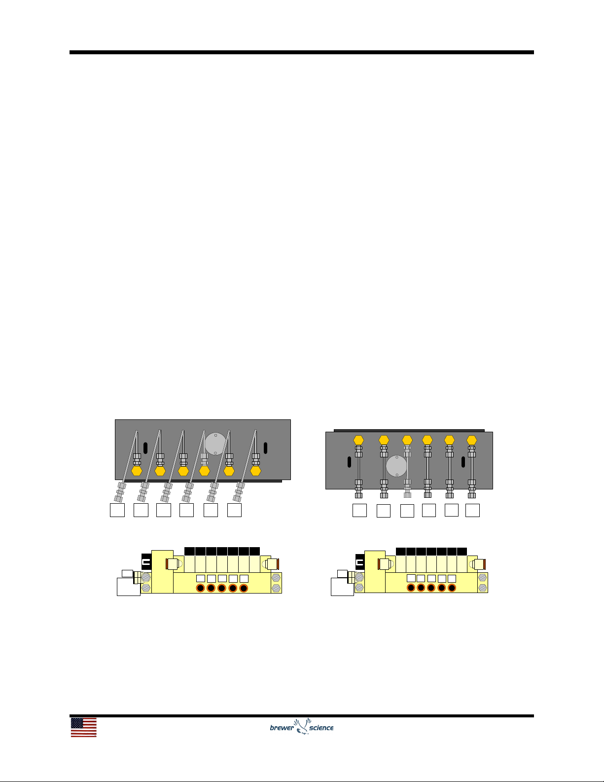
7. Run the tubing up to the platens and press into correlating stainless steel
compression nuts. The proper line destinations are numbered in figure below for
the upper and lower patens and vacuum manifolds.
8. Lightly tighten the stainless steel compression nuts with the 7/16 wrench.
9. Restrain the lines with new wire ties.
531246
53 1 246
Upper Platen Prox / Vac Lines Lower Platen Prox / Vac Lines
To
Press
Trans
1
Vac
N2
23456
To
Press
Trans
1
Vac
N2
23456
Upper Prox / Vac Manifold Lower Prox / Vac Manifold

4
1.5 Parallelism of the Lower and Upper Platen
The parallelism of the lower and upper platens should be checked quarterly or when an
issue in tool performance is noticed (vacuum loss, contaminated platen, etc.). For the
tool to be operational the lower platen must be parallel with the linear movement of the
X Axis slide and the upper platen must be parallel to the lower platen. The procedure to
check parallelism of lower and upper platens is as follows:
1. Navigate to Diagnostics – Debonder Diagnostics - Other Controls tab.
2. Wait for lift pins to lower and then move the lower platen to the press position by
pressing the Press Position button.
3. Move the lower platen up using the Z Axis controls until the lower platen is
almost touching the upper platen. The closer the platens, the more precise the
platen setup will be. The gap should be approximately 20-50 µm; enough to see
light through.
4. If the gap between the platens is not uniform from the ends of the tool, adjust the
two leveling screws on the far right of the upper platen.
a. To adjust, loosen the locking socket bolts with a 3/16-inch Allen wrench
and turn the leveling screw using the tool provided.
b. Turning the leveling screw clockwise will raise the corresponding side of
the upper platen and counter clockwise will lower it. Tighten locking socket
bolts when done.
c. If the gap is large, the lower platen may need to be lower or raised during
this step.
5. Once the gap from the side looks uniform, look at the gap from the front. If the
gap is not uniform, adjust the leveling screw on the left of the upper platen.
a. To adjust, loosen the locking socket bolt on the right with a 3/16-inch Allen
wrench and turn the leveling screw using the tool provided.
b. Turning the leveling screw clockwise will raise the corresponding side of
the upper platen and counter clockwise will lower it. Tighten locking socket
bolts when done.
c. If the gap is large, the lower platen may need to be lower or raised during
this step.
6. Once the gap is uniform from the side and the front, the parallelism of the platens
to the X Axis slide must be checked.
a. To do this, navigate to X Axis controls-Velocity Jog. Enter 200 mm into the
distance field and 5 mm/s into the velocity field.
b. Move the lower platen to the left and monitor the gap.
c. If the gap narrows, stop the platen and adjust the leveling screw on the
right of the lower platen counter clockwise. If the gap grows, the leveling
screw on the right of the lower platen must be turned clockwise. Tighten
locking socket bolts when done.
7. When an adjustment has been made to the lower platen, the upper platen will
need to be adjusted again. Move the lower platen back to the press position.
Repeat steps 5 and 6 until the gap no longer increases or decreases in step 6.
8. Once the platens are parallel, run the Vac Search Start Routine in the Setup tab.

5
1.6 Cleaning and Lubrication of the Slide Table
Cleaning of the Slide Table should be cleaned and lubricated annually or every 10,000
cycles (whichever comes first).
1.6.1 Cleaning
The cleaning process is used in Step 5 of the Lubrication Procedure in Section 1.6.2.
Before using a cleaning solvent on any part of the Slide Table, blow away small
particles and dust with clean, dry, compressed air. Any metal surface of the slide can
be cleaned with either acetone or isopropyl alcohol.
1.6.2 Lubrication
For the slide bearings, use Krytox grease.
Lubrication Procedure
1. Go to Diag – Other Controls – Distance and enter a distance of 150 mm and
move right.
2. Wait for the slide to move into position and then power down the 1300CSX.
3. Remove one of the side panels of the 1300CSX upper enclosure in order to
pull the black Slide Table cover out of the tool.
4. Remove the black slide cover off the slide (6 bolts, 3 mm allen wrench).
5. Remove any dirty or dried lubricant from the bearing rails and lead screw.
Use a clean, lint-free cloth with a side-to-side motion. Use a swab soaked in
Isopropyl Alcohol to remove stubborn debris (See Section 1.6.1)
6. Apply a thin, continuous film of lubricant to the bearing rails and lead screw. A
good quality, natural bristle artist's brush makes an excellent applicator.
7. Manually move the lower platen and repeat steps 5 and 6 for areas covered
by the original slide position.
8. Refasten the cover and side panel.
9. Power on the 1300CSX and Home.
10.Go to Diag- Other Controls and move the slide from the Home Position to the
Press Position and then back to the Home Position 5 times in order to ensure
lubricant is distributed evenly.

6
1.7 Cleaning and Lubrication of the WaferMax Z
The WaferMax Z stage should be cleaned and lubricated annually or every 10,000
cycles (whichever comes first).
1.7.1 Cleaning
The cleaning process is used in Step 5 of the Lubrication Procedure in Section 1.7.2.
Before using a cleaning solvent on any part of the WaferMax Z, blow away small
particles and dust with clean, dry, compressed air. Any metal surface of the stage
can be cleaned with either acetone or isopropyl alcohol.
1.7.2 Lubrication
For the cross-roller bearings, use Kluberplex BEM 34-132 grease. The motor is
completely non-contact and requires no lubrication.
Lubrication Procedure
1. Power down the 1300CSX.
2. Be sure the pressure to the pneumatic counterbalance is still supplied to the
stage.
3. Remove the button head screws that attach the outer covers to the stage
base and then remove the covers.
4. Remove any accumulated debris from the inside of the assembly.
5. Remove any dirty or dried lubricant from the crossed roller bearing ways. Use
a clean, lint-free cloth with a side-to-side motion. Use a swab soaked in
Isopropyl Alcohol to remove stubborn debris (See Section 1.7.1).
6. Apply a thin, continuous film of lubricant to the linear bearing ways. A good
quality, natural bristle artist's brush makes an excellent applicator.
7. Manually move the wedge to the opposite end of travel. This will work the
grease into the linear bearings. The stage table should move freely with little
resistance.
8. Repeat steps 3 through 5 for any areas covered by the original table position.
9. Refasten the covers
10.Restore power to the 1300CSX and home the stage.

7
1.8 Replacement of Filters
Replace the elements every 2 years or when the pressure drop across the filter
becomes 0.1 MPa (14.5 psi), whichever comes first, to prevent damage to the element.
Filter Replacement Instructions
1. Power down the 1300CSX, turn off and vent the N2 / CDA supply, and remove
the back panel off of the Electronics Box by removing the two thumb nuts.
ALWAYS POWER DOWN THE TOOL BEFORE TURNING OFF N2 / CDA
SUPPLY.
2. Locate the filters and remove the lines by pressing in the orange ring of the quick
connect fitting while pulling out the line.
3. Unbolt the filters from their brackets; making a note of which filter goes where.
4. Using a remove the 2 quick connect fittings off of each filter. Clean all Teflon tape
from the threads.
5. Wrap the quick connect fittings with new Teflon®tape and install on the new
filters.
6. Remove the plug from the bottom of the old filter and put into the new one.
7. Bolt the filters back onto the brackets and press the lines into the fittings on the
new filters.
8. Replace the back panel, turn on the N2 / CDA, and power the 1300CSX on.
ALWAYS TURN ON N2 / CDA BEFORE POWERING ON THE TOOL.

8
1.9 Measuring and Setting the Temperature Bias
The bias allows the operator to compensate for any difference between the sensor
temperature and the point to be measured. The process display and setpoint will be
offset by the value entered in the “Offset” parameter in the controller software. Ex:
Desired temperature is 150 degrees. Sensor is adjacent to heater and reads 50 degrees
higher than the actual process temperature. Enter bias of –50. Enter setpoint of 150.
Process will display 150 even though sensor will be measuring 200 degrees.
Measuring and Setting the Temperature Bias Instructions
1. Using a temperature calibration device, measure the temperature at the center of
the upper and lower platens.
2. Note the temperature differences of the calibration device to each of the patens.
These are the offset values.
3. From the startup screen, please select the DIAG tab at the bottom of the Display.
4. Next, press the “Exit” key to close the CeeX software and allow access to the PC
Desktop.
5. Now, locate and press the “START” menu in the lower left hand corner of the
Display.
6. Using the “START” menu, navigate and press the following:
Programs/Accessories/Accessibility/On-Screen Keyboard.
7. Next, locate the “CeeX Software” folder on the desktop.
8. Open the “CeeX Software” folder and locate the Solo-Temperature Controller
Software.
9. Upon the software opening, locate and press the Controller image/icon in the
upper right hand corner.
10. This should open an additional window. Locate the “Address Connect 1” box in
the upper right hand corner of the display. Address 1 establishes communication
to the upper platen temperature controller and Address 2 establishes
communication to the lower platen temperature controller.
11. Then, click “connect” and you should establish communication with the Solo
temperature controller.
12. The controller configuration setting should now be reflected on the screen and
locate the “P1-16 tPoF Offset” in the left side menu.
13.Using the stylus, click into this prompt box and then use the On-Screen
Keyboard to set the appropriate temperature offset.
14. After inputting the correct bias temperature, press enter on the On-Screen
keypad to save this parameter.
15. Next, close both the Solo Temperature Controller software and the On-Screen
Keypad.
16. Restart the system software, by double clicking the CeeX software Icon.
17. Upon the software initialization, navigate to the DIAG Menu and compare the
current physical temperature to the external surface probe.
18. Repeat steps 4-16, if additional bias offsetting is required.
Table of contents
Popular Industrial Equipment manuals by other brands

Maggi
Maggi 21 Prestige Use and maintenance manual

Best
Best GENIUS Compact Operator and maintenance manual

Tesmec
Tesmec CRT160 Instructions for use

ABB
ABB HT608698 Operation manual

Quantronix
Quantronix Cubiscan 110-XT Operation and technical manual

Heidolph
Heidolph Hei-VAP Industrial operating instructions


