KTR Kupplungstechnik
GmbH
D-48407 Rheine
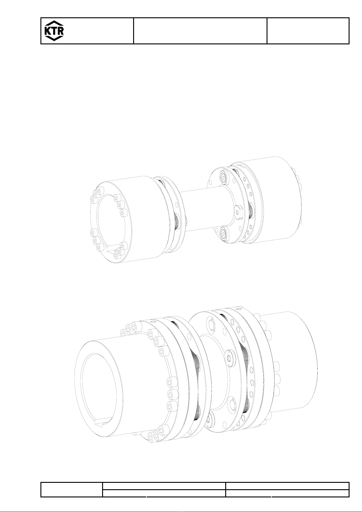
RIGIFLEX®-N
Operating-/Assembly Instructions
KTR-N
sheet:
edition:
47410 EN
4 of 19
6
Gezeichnet: 02.02.12 Kb/Sta Ersatz für: KTR-N vom 15.11.10Schutzvermerk
ISO 16016 beachten. Geprüft: 09.02.12 Kb Ersetzt durch:
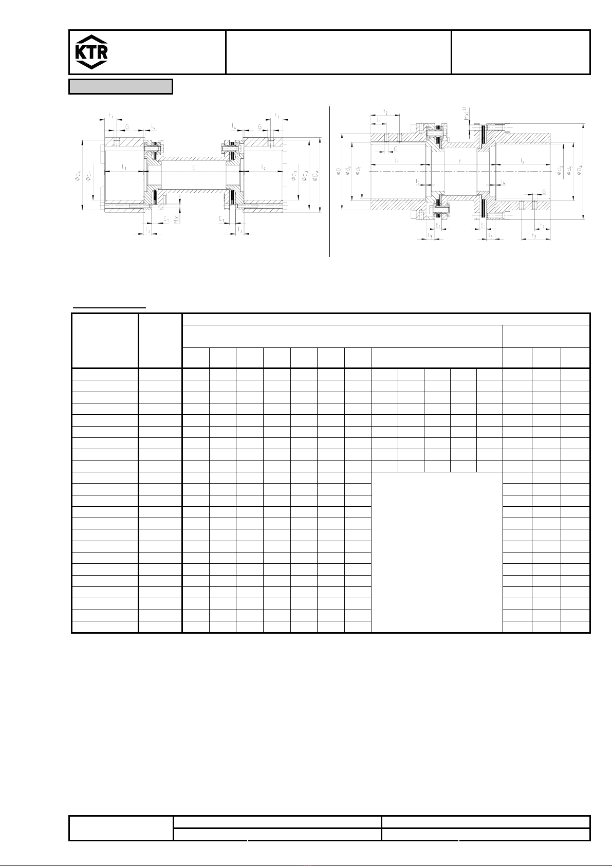
1 Technical Data
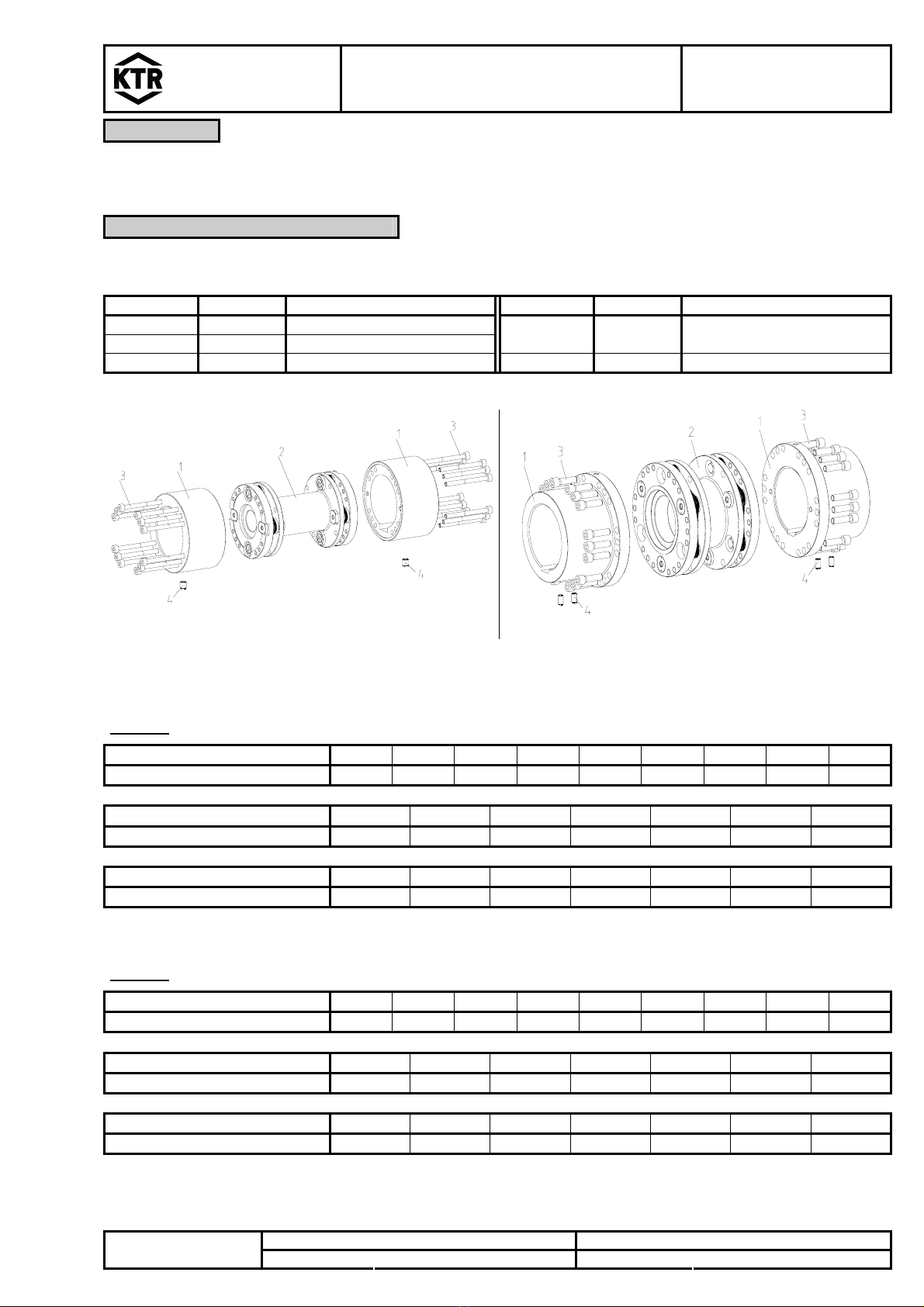
Table 2: torque and speed
RIGIFLEX®-N Size 35 50 65 75 85 110 120 140 160
TKN 120 240 450 940 1700 2700 4500 9000 13000
TK max. 240 480 900 1880 3400 5400 9000 18000 26000
Torque
[Nm] TKW 30 120 225 470 850 1350 2250 4500 6500
Max. speed n [rpm] 23000 18000 13600 12400 11000 9000 8000 6400 5600
RIGIFLEX®-N Size 166 196 216 256 306 346 406
TKN 17500 22500 32000 52500 86000 135000 210000
TK max. 35000 45000 64000 105000 172000 270000 420000
Torque
[Nm] TKW 8750 11250 16000 26250 43000 67500 105000
Max. speed n [rpm] 5600 5600 5200 4600 3900 3300 2900
RIGIFLEX®-N Size 168 198 218 258 308 348 408
TKN 23000 30000 42500 70000 115000 180000 280000
TK max. 46000 60000 85000 140000 230000 360000 560000
Torque
[Nm] TKW 11500 15000 21500 35000 57500 90000 140000
Max. speed n [rpm] 5600 5200 4600 3900 3300 2900 2500
RIGIFLEX®-N couplings with attached parts that can generate heat, sparks and static
charging (e. g. combinations with brake drums, brake disks, overload systems like torque
limiters, impellers etc.) are not allowed for the use in hazardous areas.
A separate checking must be made.
2 Hints
2.1 Coupling Selection
!
CAUTION!
For a continuous and troublefree operation of the coupling it must be designed according to
the selection instructions for the particular application (see RIGIFLEX®-N catalogue).
If the operating conditions (performance, speed, changes at engine and machine) change,
the coupling selection must be checked again.
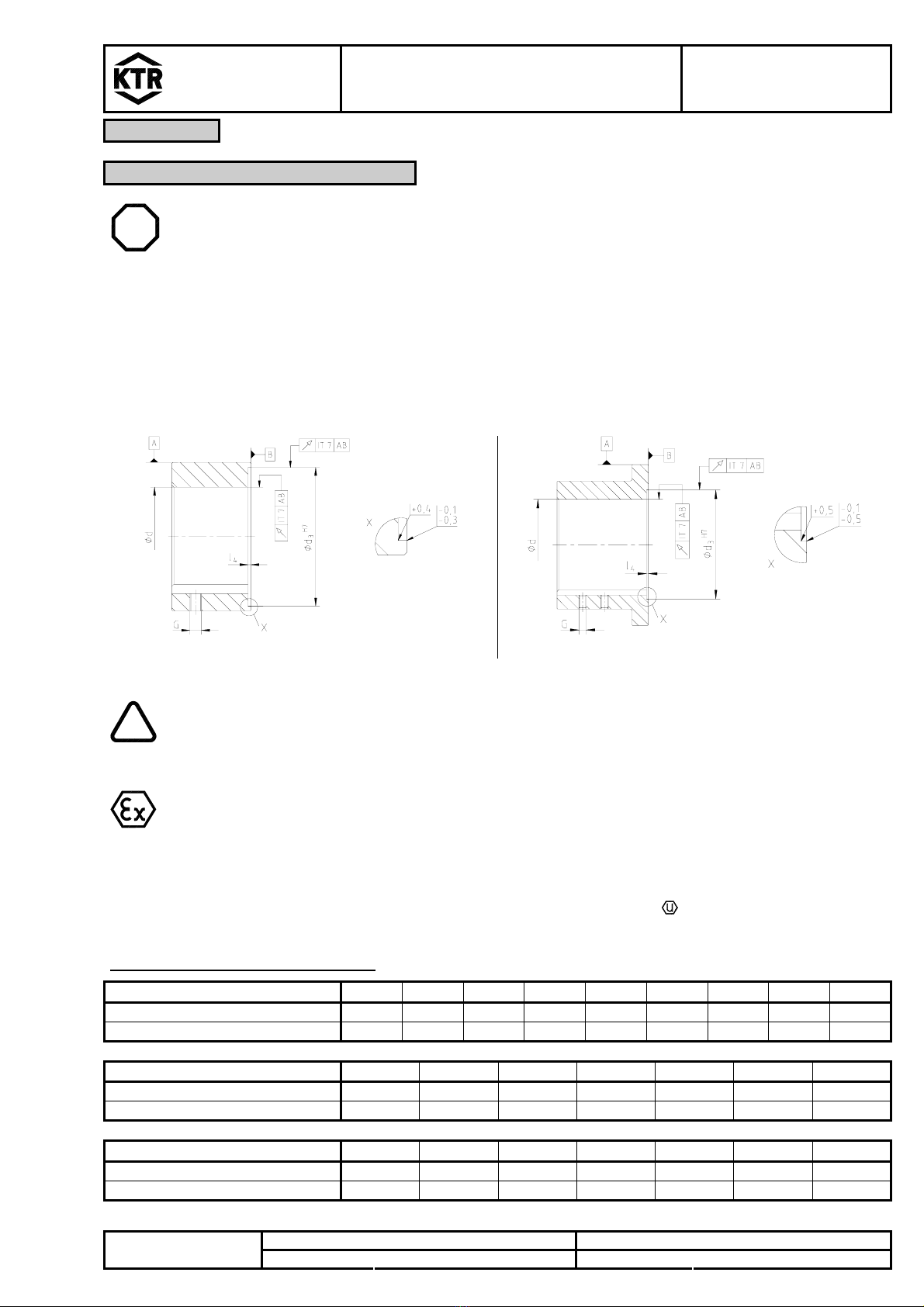
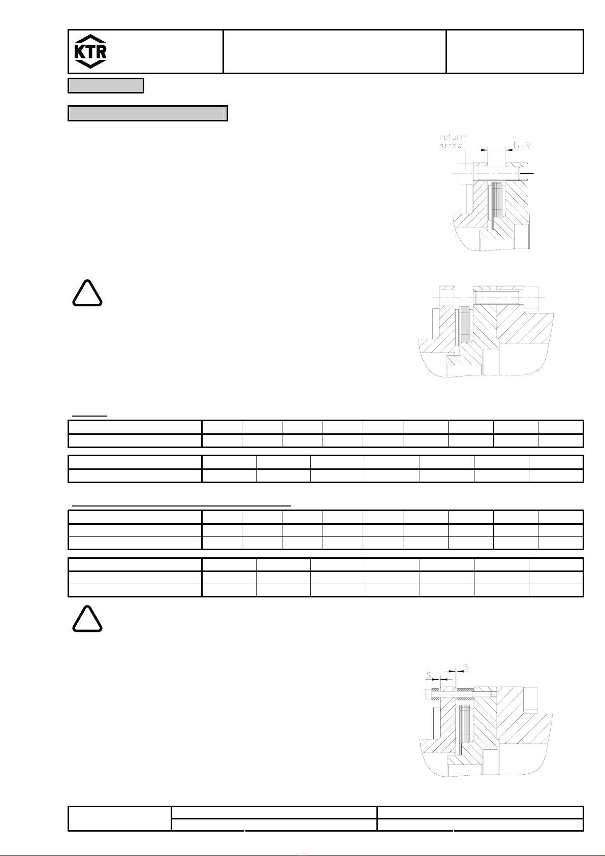
Please make sure that the technical data regarding torque only refers to the laminae
package. The transmissible torque of the shaft/hub connection must be checked by the
orderer, and he is responsible for the same.
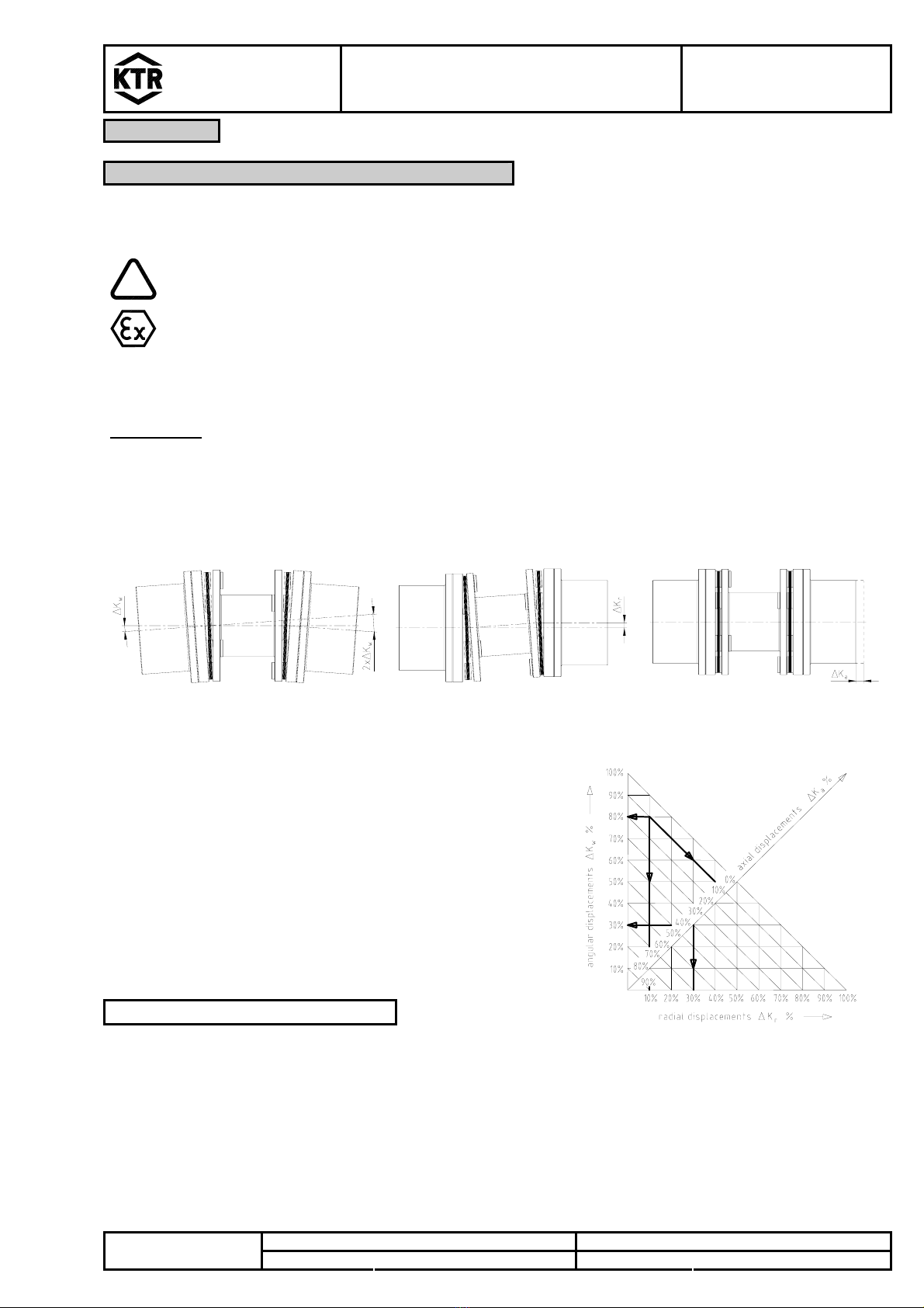
For drives with endangered torsional vibration (drives with periodical load on torsional vibration) it is necessary to
make a torsional vibration calculation to ensure a perfect selection. Typical drives with endangered torsional
vibration are e. g. drives with diesel engines, piston pumps, piston compressors etc. On request KTR makes the
coupling selection and the torsional vibration calculation.
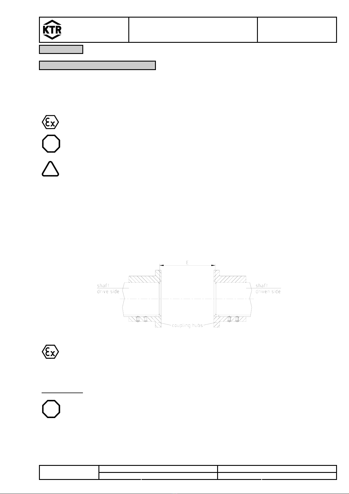
2.2 General Hints
Please read through these mounting instructions carefully before you set the coupling into operation.
Please pay special attention to the safety instructions!
The RIGIFLEX®-N coupling is suitable and approved for the use in hazardous areas. When using the
coupling in hazardous areas please observe the special hints and instructions regarding safety in
enclosure A.
The mounting instructions are part of your product. Please keep them carefully and close to the coupling.
The copyright for these mounting instructions remains with KTR Kupplungstechnik GmbH.