BriarTek ORCA User manual

Overboard Recovery
Communications
Apparatus (ORCA®)
Receiver Antenna/Cable
Installation Guide

2
This page intentionally left blank

3
1. Introduction
This document is provided as a guide when installing or replacing the
ORCA®RX antenna and cable (FSJ1RN). The installation notes provided
herein are intended to serve as a guide only. They do not serve as
material required for the certification of technicians for the installation,
repair or alteration of the ORCA®system.
2. Materials Supplied:
Line
Item Qty Description
1 1 ANC-41SP; Andrew’s VER 2 UHF Connector
2 1 Helical antenna (overmolded to bracket)
3 XX’ FSJ1RN Coaxial Cable (overmolded to bracket)
4 2 1” ¼ x 20 SWS Hex Bolt
5 4 ¼” stainless steel flat washers
6 2 ¼ x 20 stainless steel lock nuts
7 1.5” Heat Shrink, Adhesive Lined, 0.5” dia. (for UHF connector)
8 6” Heat Shrink, Heavy Duty; Adhesive Lined, 0.5" dia.
9 4” Heat Shrink, Heavy Duty; Adhesive Lined, 0.75" dia.
10 6” Heat Shrink, Heavy Duty; Adhesive Lined, 1.5” dia.
3. Existing Coax Cable Removal (if applicable)
a. Trace cable run starting at the antenna.
b. Cut the existing FSJ1RN cable at the stuffing tube.
i. The cable shield grounding adaptor (CSGA) fitting may be
reused if still in good condition.
c. Use a heat gun and apply heat to the heat shrink tubing over the
stuffing tube until the adhesive softens.
d. Remove and discard heat shrink
e. If installed, remove the CSGA compression nut and internal fittings
(grounding springs and ground spring separator) and set aside in a
safe location.
f. Remove and discard existing FSJ1RN from the stuffing tube to the
antenna.
4. New Cable Installation
a. Attach the antenna and overmolded bracket to the antenna
foundation using fasteners provided. Feed cable through heavy
duty 0.5”, 0.75” and 1.5” heat shrink tubing, CSGA fitting (if
applicable) and stuffing tube. Refer to Figure 1 for CSGA part
identification and sequence.
b. Pull cable through stuffing tube and into vessel’s interior

4
c. Measure cable to reach receiver display. Leave sufficient slack (6-
12 in.).
d. Ensure there is sufficient cable length to connect the UHF
connector to the RX102 receiver. Install Andrew’s 41SP UHF
Connector (see Attachment 1)
5. Assemble the CSGA Fitting (if applicable)
a. Refer to figure 1 for CSGA fitting nomenclature
b. Ensure that there is sufficient slack in the cable between the
stuffing tube and the receiver antenna to conform to the previously
installed cable run. Leave an excess of 6” – 8” of cable to allow for
easy installation and removal of the receiver antenna.
c. Position cable at its final install location and mark the position
where the cable exits the CSGA adaptor.
d. Insert packing material in stuffing tube.
e. Slide washer on top of packing material.
f. Insert CSGA adaptor into stuffing tube and tighten using crescent
wrench.
Stuffing tube
Packing material
Washer
CSGA adaptor
(2) Ground spring Separator
Compression nut
Figure 1

5
g. Strip 1” – 1 1/2” of the cable’s jacket. See figure 2.
i. Do not nick the cable’s braided shield
ii. There may be thin cellophane over the braided shield. This
must be removed.
h. Slide ground springs and separator over exposed braided cable
shield and position to the base of the CSGA adaptor. See figure 3.
i. Apply anti-seize to the CSGA adaptor’s threads and tighten
compression nut to 300 in/lbs. See figure 4.
Figure 3
Figure 2

6
6. Apply heat shrink
a. Slide 0.5” diameter heat shrink tube to the base of the CSGA
compression nut (see figure 5) or base of stuffing tube as
applicable.
b. Ensure there exists a sufficient bend in the cable. See figure 6.
Figure 4
Figure 5

7
i. Apply heat evenly to entire tube using a 750-watt heat gun.
Ensure adhesive seals around the perimeter of the tube and
onto the cable.
ii. Repeat process with 0.75” diameter heat shrink tubing
iii. Slide 1.5”
diameter heat
shrink tubing
such that it
covers at least 2”
of the stuffing
tube, the CSGA
assembly (if
applicable) and
2” of the 0.75”
diameter heat
shrink tubing.
iv. Apply heat
evenly to entire
tube using a
750-watt heat
gun. Ensure
adhesive seals
around the
perimeter of the
tube and onto
the stuffing tube
and the smaller
heat shrink tube.
See figure 6.
7. Connect UHF connector to receiver, energize circuit and turn on RX-102
receiver at power button.
8. Perform system operational verification test (SOVT).
a. Activate ORCA®transmitter from the stern of the vessel.
b. When signal is detected by the receiver, ensure the audible alarm
activates and the LCD displays the vessel ID, transmitter ID (serial
number), the transmitter battery strength (Good or Weak) and the
RSSI (received signal strength indicator).
c. Deactivate transmitter.
Figure 6
cable
bend
heat shrink -
stuffing tube

8
9. For additional assistance, please contact BriarTek at 703-548-7892 or
through our website at www.briartek.com.
© 2011 BriarTek, Inc.

9
Attachment 1
Andrew’s 41SP UHF Connector
Assembly Instructions

Bulletin 237517
Installation Instructions
Original Issue
UHF Connector
for HELIAX®FSJ1-50A Coaxial Cable
2
Cut outer conductor.
Cortar el conductor externo.
Coupez le conducteur
extérieur.
Außenleiter zurückschneiden.
Corte o condutor externo.
3
Remove foam and adhesive.
Retirar el material de espuma y
el adhesivo.
Enlevez la mousse et l'adhésif.
Verschäumung und Klebeband
entfernen.
Remova a espuma e o adesivo.
4
Add shrink tube and coupling nut
Añada el tubo corrugado y la tuerca de
acoplamiento.
Mettez en place la gaine thermorétractable
et l'écrou d'assemblage.
Schrumpfschlauch überziehen und
Klemmutter montieren.
Adicione o tubo de redução e a porca de
acoplamento.
5
Place adaptor flush with outer
conductor and solder them together
Coloque el adaptador al mismo nivel
que el conductor exterior y suéldelos
entre sí.
Alignez l'adaptateur sur le
conducteur extérieur et soudez ces
deux éléments.
Adapter bündig mit Außenleiter
ausrichten und zusammenlöten.
Coloque o adaptador junto ao
condutor externo e solde-os.
1000 W 150 W
63/37 RMA
41SP
Inches 2 3 41
Millimeters 20 30 40 50 60 70 80 90 100
11/16”
(17 mm)
1-5/8”
(41 mm)
1
Trim cable jacket.
Recortar la envuelta del cable.
Coupez la gaine du câble.
Kabelmantel abziehen.
Retire a capa do cabo.
Tips and Techniques (SP50047) available by FAX-On-Demand.
Los consejos prácticos y técnicas (SP50047) pueden solicitarse por fax. Conseils et techniques (SP50047) disponibles par fax à la demande.
Tips und Anleitungen (SP50047) auf Faxanfrage erhältlich. Dicas e Técnicas (SP50047) disponíveis via pedido por fax.
FAX-On-Demand:
+1-708-873-3614 • North America: 1-800-861-1700
6
Screw inner connector onto adaptor to a torque value of
from 32-40 lb-in (3.7-4.5 N·m) and solder together.
Atornille el conductor interior en el adaptador, a un par
entre 32 y 40 lib-pul o (3.7 y 4.5 N-M) y suéldelos entre sí.
Vissez le conducteur intérieur sur l'adaptateur à un couple
de 3,7-4,5 N.m et soudez ces deux éléments.
Innenleiter auf Adapter schrauben, mit 3,7-4,5 Nm
anziehen und zusammenlöten.
Atarraxe o condutor interno no adaptador a um valor de
torque de 32 a 40 lb-pol. (3.7-4.5 N.m) e solde-os.

Andrew Corporation
10500 West 153rd Street
Orland Park, IL U.S.A. 60462
Telephone: 708-349-3300
FAX (U.S.A.): 1-800-349-5444
Internet: http://www.andrew.com
Customer Service, 24 hours: U.S.A. • Canada • Mexico: 1-800-255-1479
U.K.: 0800 250055 • Republic of Ireland: 1 800 535358
Other Europe: +44 1592 782612
Printed in U.S.A. 10/98
Copyright © 1998 by Andrew Corporation
7
Solder inner connector and
outer conductor together
Suelde el conector interior
y el condutor interior entre
sí.
Soudez les connecteurs
intérieur.
Innenleiter zusämmenlöten
Solde o conector interno ao
condutor interno.
8
Screw coupling nut beyond threads of inner
connector so nut spins freely
Atornille la tuerca de acoplamiento hasta pasar las
roscas del conector interior, de modo que la tuerca
gire libremente.
Vissez l'écrou d'assemblage au-delà des filets du
connecteur intérieur, pour que l'écrou tourne
librement.
Klemmutter über das Innenleitergewinde hinaus
drehen, so daß sich die Mutter frei dreht.
Rosqueie a porca de acoplamento além da rosca do
conector interno para permitir o giro livre da porca.
9
Apply heat shrink tube.
Aplicar el tubo de termoencongimiento.
Mettez en place la gaine thermorétractable.
Schrumpfschlauch überziehen.
Aqueça o tubo plástico.
This product may be covered by one or more of the following patents, or other patents pending. United States 5,154,636; 5,137,470; 5,354,217; 5,344,051; 5,435,745; 5,595,502;
Switzerland, Spain, France, United Kingdom 0 495 467; Germany P692 13 034.9; p692 14 199.5; Italy 70,732-BE/96; 71,436-BE/96; Australia 668,812
Notice: Andrew disclaims any liability or responsibility for the results of improper or unsafe installation, inspection, maintenance, or removal practices.
Aviso: Andrews no acepta ninguna obligación ni responsabilidad como resultado de prácticas incorrectas o peligrosas de instalación, inspección, mantenimiento o retiro.
Avis : Andrew décline toute responsabilité pour les conséquences de procédures d'installation, d'inspection, d'entretien ou de retrait incorrectes ou dangereuses.
Hinweis: Andrew lehnt jede Haftung oder Verantwortung für Schäden ab, die aufgrund unsachgemäßer Installation, Überprüfung, Wartung oder Demontage auftreten.
Atenção: A Andrew abdica do direito de toda responsabilidade pelos resultados de práticas inadequadas e sem segurança de instalação, inspeção, manutenção ou remoção.
This manual suits for next models
1
Table of contents
Popular Antenna manuals by other brands
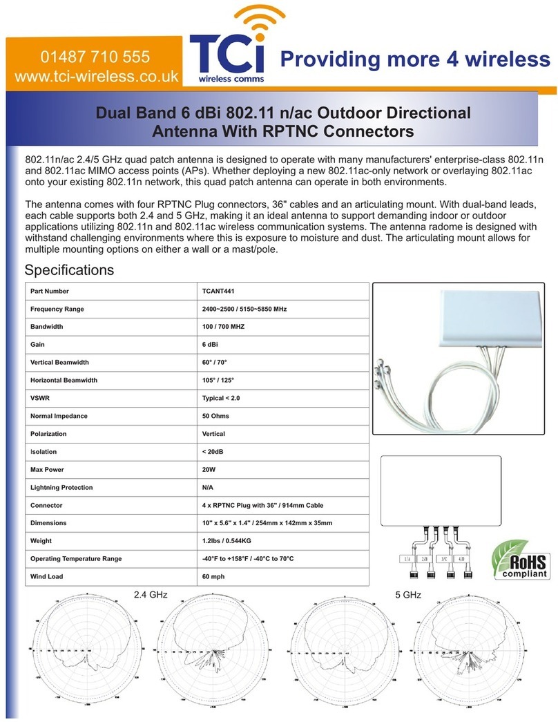
TCi
TCi TCANT441 Mounting Information
BEST BUY essentials
BEST BUY essentials BE-ANT716 Quick setup guide
ImmersionRC
ImmersionRC 5.8GHz SpiroNET 13dBi instruction manual
Matsing
Matsing MS-12.6DB180 instruction manual
TerraTec
TerraTec Antenna 300 Quick setup guide

WADE Antenna, Inc.
WADE Antenna, Inc. Taco Antenna D4000 Series Instruction booklet
