BriarTek ORCA RX-102 User manual

Overboard Recovery
Communications
Apparatus (ORCA®)
RX-102 Receiver
User’s Manual

3
This page intentionally left blank

4
For technical support, contact BriarTek at 703-548-7892 or through our website at
www.briartek.com.
© 2011 BriarTek, Inc.
5
Introduction
ORCA®(Overboard Recovery Communications Apparatus) is a personal water-activated man
overboard (MOB) alarm system developed by BriarTek Incorporated and utilized by the US
Department of Defense and other mariners. The alarm system includes a transmitter, receiver and
direction finder. The RX-102 receiver is a single channel VHF (121.5 MHz) receiver with an
embedded microprocessor and push button interface. The RX-102 is designed to receive a signal
from an ORCA®transmitter. When an ORCA® transmitter is activated, the transmitter emits a radio
frequency (RF) signal. A visual and audible (100 dB) alarm on the receiver sounds upon receipt of
this signal indicating the identity of the MOB. If the transmitter is not disabled within one (1) minute,
it will begin transmitting a signal that is processed by the direction finder, providing a continuous
bearing to the MOB.
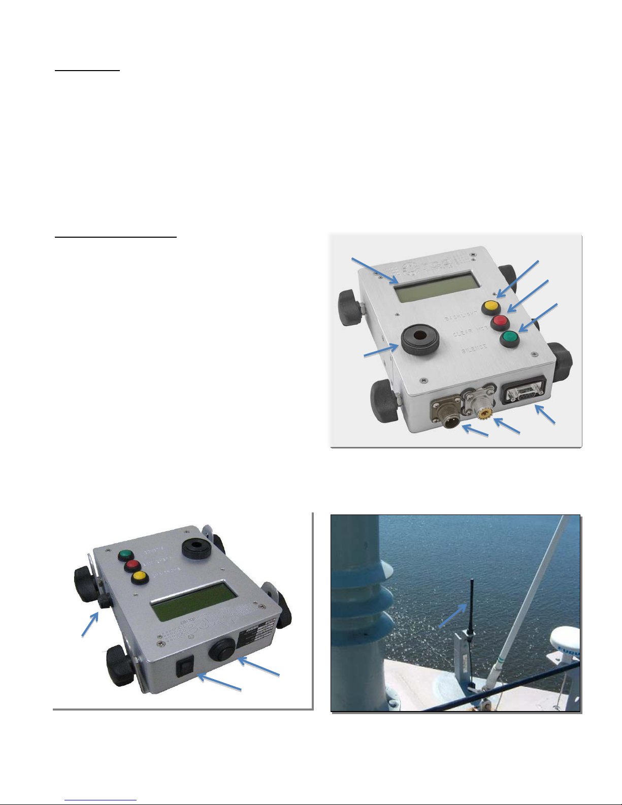
RX-102 Parts Overview
A- Liquid Crystal Display (LCD)
B- Backlight (Yellow)
C- Clear MOB (Red)
D- Silence (Green)
E- Piezoelectric Buzzer
F- Serial Connector
G- Antenna Jack
H- Power Jack
I – Volume Control
J- Power On/Off
K- Fuse Holder
L- Helical Antenna
Figure 3. RX-A102 Antenna
Figure 2. RX-102 (top end view)
Figure 1. RX-102
A
E
H
G
F
D
C
B
J
K
I
L

6
RX-102 Operating Instructions
Activation and Receiver Display
a. When a transmitter from own ship is activated, an alarm signal (continuous warble) is
sounded at the receiver buzzer. The vessel identification and transmitter serial number
are displayed on the LCD.
b. When a transmitter from another vessel is activated and within range, an alarm signal
(chirp) is sounded and the vessel identification as well as the serial number of the
transmitter, is displayed on the LCD.
c. When an alarm signal is received, whether own ship or other vessel, line 4 will indicate
the transmitter’s battery strength, “Good” or “Weak.”
d. Received Signal Strength Indication (RSSI) is also displayed on line 4 of the LCD. RSSI
is a measure of the field strength (radio waves at 121.5MHz), at the antenna input.
NOTE
RSSI is not a measure of beacon signal strength.
This indicator is useful for several reasons: It can help determine if a non-ORCA® signal
is interfering with the operation of the ORCA® system. It can help to diagnose problems
with the ORCA® equipment, such as broken antenna cables.
NOTE
RSSI is expressed in negative numbers, -141dBm being
the weakest and -10 dBm being the strongest signal.
Typically if no systems are interfering with the ORCA®
system and there are no beacons turned on, the
background signal strength level will be between -130 and
-110 dBm. If the background RSSI is stronger than -90
dBm (-10dBm > RSSI > -90 dBm), then the ORCA®
beacon will not be able to be received except in very close
proximity to the ship.
Audible Alarm - When the receiver detects the FM signal emitted by the transmitter, the buzzer
emits a 100 dB (max) audible alarm. The audible alarm will continue to sound until either the
transmitter is turned OFF, sending an "All Clear" signal to the receiver; or the Silence button is
pressed.
Volume - The receiver's volume can be adjusted to 1 of 2 settings using the volume control
toggle switch.

7
Visual Alarm Display
a. The LCD is a 4 x 20 character display.
b. If no ORCA® signal is present -
Line 1: “Scanning”
Line 4: RSSI
b. If ORCA® signal is detected -
Line 1: Vessel ID; transmitter serial number
Line 4: ORCA® transmitter battery strength (“Battery Good/Weak”); RSSI
Backlight Button (Yellow) - During low light or no-light situations, press the Backlight button (B)
to illuminate the LCD. Press the Backlight button again to turn off illumination.
NOTE
Pressing Backlight button during "darken ship"
operations is not recommended due to interference
with night vision.
Clear MOB Button (Red) - Press the Clear MOB button to remove ID(s) from receiver’s memory.
This function is provided to allow the user the ability to remove the ID information from the
receiver in the event it did not receive the "All Clear" from a transmitter after a successful rescue
or during testing.
Silence Button (Green) - Press the Silence button to silence the audible alarm.
Installation Notes
The installation notes provided herein are intended to serve as a guide only. They do not serve
as material required for the certification of technicians for the installation, repair or alteration of
the ORCA® system.
a. General
The RX-102 is typically installed in the pilothouse and should be mounted in a location
so that the audible alarm is easily heard, the push buttons are easily accessible and the
LCD is readable by watch standers.
b. Mounting the receiver
The receiver should be mounted to a fiddleboard or part of the super structure such as a
bulkhead. Mount the receiver brackets using appropriate fasteners (self-tapping screws
or 1/4x20 machine screws with locknuts/washers). The receiver brackets are designed
with slots to allow for flexibility in mounting the receiver. Once the brackets are securely
mounted, secure the receiver to the brackets by inserting the threaded mounts (4) into
each of the bracket side slots (2 each x 2 brackets). Finally, adjust the angle of the

8
receiver by tilting forward or back as desired and thread the knobs (4) onto each of the
threaded mounts until snug.
c. Power connection
Twelve or twenty four volts DC is required to provide power to the system. An optional
battery backup will supply power to the receiver for 1 hour in the event power to the
circuit is lost.
d. General
The receiver antenna should be located in an elevated location (above the pilothouse or
vessel’s mast) to ensure that the ORCA® signal is received. The higher the antenna is
mounted, the better range can be expected. In addition, to avoid signal loss caused by
excessive cable length, the coaxial cable length between the RX 102 receiver and
antenna should not exceed 150 feet.
e. Mounting the receiver antenna
The receiver antenna is over molded to a 90stainless steel bracket and coaxial cable.
The bracket has 2 holes which are used for securing to a foundation (see RX-102
Antenna specifications for hole dimensions). The foundation should be a similar metal as
the super structure or mast to which the foundation is being welded. A UHF connector is
supplied with the antenna/cable. For cable assembly and installation instructions, follow
the guidance provided in the Receiver Antenna/Cable Install Guide located on the
BriarTek website.
Maintenance And Troubleshooting
Inspection
a. Inspect receiver for excessive wear.
b. Check for salt buildup at the coaxial cable connector to the receiver, as this may indicate
saltwater intrusion at the antenna mount connector.
c. Inspect antenna and antenna mount for excessive wear.
d. If any parts are broken, missing or excessively worn, replace as necessary.
Testing - Ensure antenna is connected to UHF coaxial antenna connector and receiver is
plugged into power source. With one individual at the receiver to observe receiver alarm, and a
second individual operating the transmitter from the bow or stern (whichever is further from the
antenna) of the vessel, perform operational test of the RX-102 as follows:
NOTE
Record transmitter serial number for the test. Serial
number is located on side of transmitter.

9
NOTE
Before beginning full system testing, notify
pilothouse and other ORCA®-equipped vessels
within range that testing of the ORCA® system will
occur.
a. If receiver is not already on, turn on receiver at rocker switch.
b. Press the backlight (yellow) button to illuminate LCD. Press backlight button again to
turn off LCD illumination.
c. Activate ORCA® transmitter (if using a TX-103 transmitter, rotate the manual switch
from the OFF position to the ON position. If using a TX-104 transmitter, short the two
water contacts using a 5"-10" long wire or submerge transmitter in saltwater until
transmitter DML illuminates).
a. Ensure RX-102 LCD displays the serial number of the transmitter.
b. After the RX-102 audible alarm activates, toggle the volume switch between low and
high.
c. Press the Silence (green) button to silence the alarm.
d. Deactivate ORCA® transmitter (if using a TX-103 transmitter, rotate the manual switch
from the ON position to the OFF position; if using a TX-104 transmitter, align the
antenna tip with the round recess on the face of the transmitter until the DML stops
illuminating).
e. Ensure LCD displays “All Clear MOB ####" on line 1 and “Batt. Good/Weak” on line 2.
f. Activate ORCA® transmitter. Remove battery from transmitter. Press Clear MOB (red)
button. Observe LCD displays “Clearing MOB list. Erasing. Please Wait. Done”.
Troubleshooting - In the event of equipment malfunction, perform troubleshooting procedures:
a. Power failure:
(1) Ensure power switch is turned ON.
(2) Ensure receiver is connected to power source:
- Check power at power supply / battery backup (if installed) using voltmeter.
- Check power at power panel.
(3) Inspect fuse in fuse holder.
If receiver still fails to turn on, replace receiver.
b. Receiver does not receive signal from ORCA® transmitter:
(1) Ensure UHF antenna cable connector is securely fastened to antenna jack.
(2) Trace antenna cable for broken/frayed wire.
(3) Ensure antenna is securely mounted to bracket and connected to cable.
If receiver still fails to receive signal from ORCA® transmitter, replace receiver.
c. Receiver does not display “Scanning” during normal scanning mode (no transmitter
activated):
Turn OFF receiver at Power On/Off rocker switch; wait 5 seconds and turn ON.

10
If receiver still displays “Scanning”, replace receiver.
d. RSSI consistently displays -90 dBm or stronger:
(1) Determine if there are any active emitters transmitting at/near 121.5 MHz. If so, turn
off emitters.
(2) Observe RSSI.
(3) If RSSI is still reading strong, determine if emitters from another source (ship or
ground-based) are active.
If above troubleshooting steps do not address the problem and the receiver has been put in
service within the past year, contact BriarTek. Provide the following information:
- Ship Name
- Time observed (number of days or hours)
- Which radiating systems were being used at the time (e.g. Navigation Radar)
- Ship's general location/operating area

11
Parts List
System Subsystem Part Number Component Description (Nameplate Data) Mfr
ORCA Receiver ORCARX-102
Receiver: 100 db audible alarm; touchscreen
LCD; hardened enclosure; mounting bracket;
121.5 MHz; power requirement - 12 VDC
BriarTek
ORCA Receiver ORCARX-A102
Receiver antenna: Overmolded helical
antenna with mounting bracket and Heliax
cable; includes UHF connector
BriarTek
12
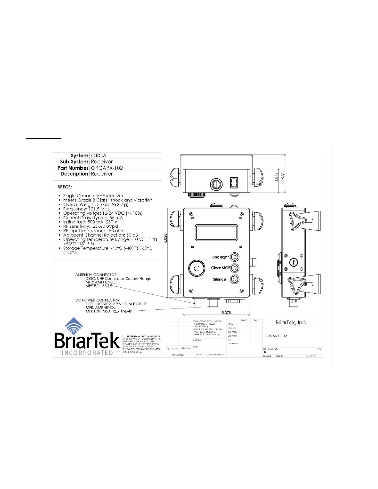
Specifications

13

14
Warranty
BriarTek will provide a one-year warranty on the ORCA®man overboard alarm system
following the date of original purchase.
If a component fails to function properly during its warranty period (one year), the
manufacturer will proceed according to its warranty as follows:
BriarTek Inc. guarantees each product it distributes to be free from defective materials
and workmanship and agrees to remedy any such defect, or to furnish a new or equal
part in exchange (at its option) for a period of one year from the date the component is
purchased. For an exchange of the product, please contact BriarTek at 703-548-7892
or on the web at www.briartek.com and a customer service representative will provide
the necessary instructions.
This warranty is void if:
any component has been subject to misuse or improper installation by a non-
BriarTek employee, or has been repaired or altered by a non-BriarTek employee.
any component fails to function properly after being put into service due to
something other than defective materials or workmanship, i.e. excessive
temperature, humidity or shock while component is in storage.

15
Notes:

16
Notes:
This manual suits for next models
1


