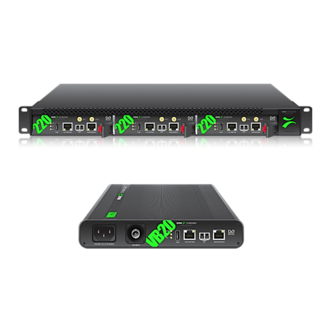
BridgeTech VB20 User manual

This guide covers the following Bridge Technologies devices: VB120, VB20, VB220
and VB330. Oponal interface modules, like demodulators, do not require inial
set-up. For further informaon download the User Manual and refer to secon
4.1. The serial number can be found on the unit.
Note: that individual probes in a chassis must be configured separately.
These modules have a USB port.
Manuals can be downloaded from the end-user log-in area of Bridge
Technologies’ web site
www.bridgetech.tv - click Login
user name: customer
password: xmas4u
Health and safety
Read the safety chapter of the User’s Manual, to avoid potenal hazard.
Technical support
Contact your Bridge Technologies Partner/Reseller or refer to your support
agreement.
Warranty/Soware Upgrades/Training/General enquiries
Contact your Bridge Technologies Partner/Reseller.
Unpack Equipment
Check that there are no obvious damages to equipment due to transport. If
equipment appears to be damaged, please contact your Bridge Technologies
reseller for support.
In addion to the Bridge Technologies hardware itself, the shipment should
include a power cable (two for enhanced chassis) and a USB cable.
Install Equipment and Power Up
Equipment designed for rack installaon should be securely connected to the
rack using rack screws suitable for the rack type.
Note that there should be sucient room for air to freely ow around
the unit, ensuring proper cooling. Also note the direcon of air ow for
your chassis type prior to installaon (refer to the User’s Manual).
When the equipment is installed, it can be powered up by connecng it to a
power outlet using the power cable(s). Bridge Technologies devices for AC mains
can operate in the range 100–240VAC. Refer to the User’s Manual for a
descripon of DC power connecon.
InitialConguration
There are 2 alternave ways of performing an inial configuraon:
1. Preconfigured IP address of the probe management port (Go to 1.)
2. Via serial console emulated over USB (Go to 2.)
In the box: Monitoring Probe + Power cord & supply USBA-A Cable
QUICK START GUIDE
Quick Start Guide Monitoring Probe v1 ©BRIDGE Technologies Co AS
1

1. Conguration Using the Pre-Set IP-Address
The factory sengs for the
wired management interface are:
Management (eth1) IP address: 10.0.20.101
Management (eth1) subnet mask: 255.255.0.0
In order to connect to the eth1 management port, the PC used for set-up should
have corresponding network sengs. Connect directly to the device’s eth1
management port using an Ethernet cable.
For Windows, the network parameters are set in the Control Panel - Network
and Internet - Network and Sharing Center - Local Area Connecon - Properes
- Internet Protocol Version 4 Properes. Select the user defined address.
Set the PC’s IP address to 10.0.20.100 and the subnet mask to 255.255.0.0.
When the IP address of the PC has been set to match the device’s factory seng,
the permanent network sengs can be configured through the regular web
browser interface.
2. Connecting to the serial console over USB
For the inial set-up, do the following:
1. Install a driver for the USB communicaon
(if not already supported by the operang system)
2. Set the management IP address
Most operang systems will have nave support for the FT232 driver needed.
When a USB cable is connected between a PC and the monitoring probe, the
operang system will detect a new USB device. For Windows, the new device will
appear as a COM port in the Device Manager shown below.
If the operang system does not detect the probe, download and install a driver
for it from the chip manufacturer at hp://www.dichip.com/. Select first Drivers,
then VCP followed by the operang system (VCP is short for Virtual COM Port).
If it is not already connected, connect the USB cable between the USB port on
the probe and a USB port on the PC.
Quick Start Guide Monitoring Probe v1 ©BRIDGE Technologies Co AS
2

Start a terminal program.
- Windows XP users can use Hyperterm
- Linux users can use Minicom
For later versions of Windows, that do not ship with a terminal program, the free
applicaon PuTTY may be downloaded from:
hp://www.chiark.greenend.org.uk/~sgtatham/puy/
Select the new COM port that appears as the USB cable is plugged in (Linux users
should check /var/log/messages to see what device to use) and establish a serial
connecon to the monitoring probe, using these communicaon parameters:
• Baud rate: 9600
• Data bits: 8
• Parity: None
• Stop bits: 1
• Flow control: None
Press ENTER a few mes to bring up the login prompt.
Log in using the user name admin and the password elvis.
A simple text based menu system should now be displayed. To change a seng,
press the appropriate character from the le-most column, enter the new value
and confirm by pressing ENTER. If DHCP is enabled, you can find the currently
assigned IP address by selecng the ethStatusDoc opon.
The monitoring probe is equipped with two network interfaces called manage-
ment (or eth1) and data/video (or eth0).
Congure at least one of the interfaces from the terminal and
then do the rest of the setup from a web browser.
Depending on the installed license, an addional data interface, labelled data2
(eth2), may also be available.
The monitoring probe supports both in-band management (i.e. using eth0 for
both data/video and management) and separate management (i.e. using eth1 for
management). In any case make sure that the subnets configured for eth0 and
eth1 do not overlap – otherwise the probe will not work properly.
Note that if IP addresses for eth0 and eth1 are configured so that the
subnets overlap, the IP address of one of the ports will be automacally
set to 1.1.1.1 by the monitoring probe.
Conguring the management interface:
Edit values for IP address, netmask and mm_gateway or enable dhcp instead.
Make sure Management is enabled (set to true) – otherwise management via
web will not be possible.
Conguring the data/video interface:
Enter values for data_ipa, data_mask, data_gateway or al- ternavely enable
data_dhcp. Set data_management to true to enable web access via the data
interface. When all the listed parameters have been configured, the probe must
be rebooted to let the parameters take eect. This is achieved by selecng the
reboot opon and confirming by selecng ‘t’ for TRUE.
Quick Start Guide Monitoring Probe v1 ©BRIDGE Technologies Co AS
32

For more informaon refer to user manual, secon 5 & 6.
Verifying Correct Initial Setup
Once the probe management network interface has been configured, all further
configuraon takes place using a web browser over HTTP.
Launch a web browser applicaon on the management PC.
The following web browsers are supported:
• Microso Edge
• Microso Internet Explorer 11 or higher
• Mozilla Firefox 29 or higher
• Google Chrome
• Apple Safari
Type the IP address of the probe, as set in the inial set-up procedure, in the
browser URL field and press ENTER.
The default management view should be displayed inside the browser. The
interface is shown below. Some funconality may require addional licenses to
be installed.
Check Licensing
Check that the device licensing is correct in the About - License view.
Set Network Parameters
Set Ethernet network parameters. This is done in the Setup — Ethernet view.
Connect Media Signals
Connect media signal cables. Depending on the device hardware and soware
opons this might include:
• Ethernet cable carrying mulcast and/or unicast streams
• Coax cable carrying an ASI/MPEG-2 transport stream
• RF cable carrying a modulated signal
Dene Input Signals
ASI
An ASI signal needs no parameter sengs; it is automacally detected by the
probe and monitored by default. Refer to the User’s Manual for configuraon of
the oponal VB242 Mulple ASI Input module.
Ethernet
The probe will only monitor streams that are configured and joined. This is done
in the Ethernet - Mulcasts view.
RF signal
RF parameters are set in the <RF> — Tuning Setup view. Check the RF input LED
for signal lock once parameters have been set.
Verify Correct Operation
When input signal definion has been performed the device will start monitor
ing. Check relevant monitoring views for correct device operaon.
Quick Start Guide Monitoring Probe v1 ©BRIDGE Technologies Co AS
4
Other manuals for VB20
1
This manual suits for next models
3
Table of contents
Other BridgeTech Measuring Instrument manuals
Popular Measuring Instrument manuals by other brands

Banner
Banner SureCross FlexPower DX80 Series instruction manual

Konica Minolta
Konica Minolta CA-100PLUS instruction manual

Knick
Knick Stratos Pro A401B PH user manual

Keysight
Keysight N777 C Series Programming guide

DGH
DGH Pachette 2 Operator's manual

Endress+Hauser
Endress+Hauser Promag 800 L Installation instruction

Endress+Hauser
Endress+Hauser 2-Pack TDLAS Safety instruction

Endress+Hauser
Endress+Hauser Proline t-mass 65 MODBUS RS485 manual

Ecomatik
Ecomatik DF5 user manual

Pfeuffer
Pfeuffer HFM operating instructions

PureAire
PureAire Air Check O2 instruction manual

Hanna Instruments
Hanna Instruments HI 2221 instruction manual