manuals.online logo
Brands
  1. Home
  2. •
  3. Brands
  4. •
  5. turck
  6. •
  7. Measuring Instrument
  8. •
  9. turck FCI-X-H114 Series User manual

turck FCI-X-H114 Series User manual

FCI-…X-H114…
Documents supplémentaires
Vous trouverez les documents suivants contenant des informations complémentaires à la
présente notice sur notre siteWeb www.turck.com:
■Fiche technique
■Déclarations de conformité
Pour votre sécurité
Utilisation conforme
Les capteurs de débit en ligne avec électronique de traitement intégrée sont utilisés pour la
surveillance du débit d’eau, d’huiles, d’alcools, de peintures ainsi que de liquides et de gaz non
explosifs.
Les appareils sont conçus pour être montés en ligne dans une tuyauterie. En raison du principe
de fonctionnement calorimétrique, les appareils sont sans usure.
Les appareils doivent exclusivement être utilisés conformément aux indications figurant dans
la présente notice. Toute autre utilisation est considérée comme non conforme. La société Turck
décline toute responsabilité en cas de dommages causés par une utilisation non conforme.
Mauvaises utilisations prévisibles
Les appareils ne constituent pas des composants de sécurité et ne peuvent pas être utilisés à
des fins de protection des personnes ou des choses.
Consignes de sécurité générales
■Seul un personnel qualifié est habilité à monter, installer, faire fonctionner, paramétrer et
effectuer la maintenance de l’appareil.
■L’appareil répond aux exigences CEM pour le domaine industriel. Lorsqu’il est utilisé dans
des zones résidentielles, prenez des mesures pour éviter les interférences radio.
Description du produit
Aperçu de l’appareil
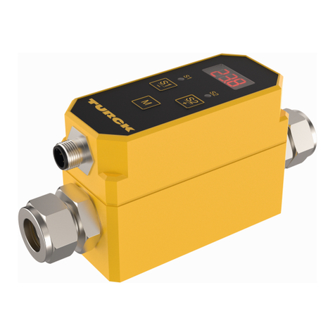
Voir fig.1: Image du produit (exemple), fig.2: Position des potentiomètres.
Fonctions et modes de fonctionnement
Le type de sortie, les fonctions de détection et le nombre de potentiomètres des capteurs de
débit en ligne sont indiqués dans le tableau suivant:
Type Type de sortie Valeurs de processus
détectées Potentiomètre
FCI-…-LIX-… Sortie analo-
gique, 4…20mA Etat du débit, état de
la valeur de consigne,
présence du milieu, vitesse
du débit
1 ou 2
FCI-…-AP8X-… Sortie de commu-
tation, PNP, N.O. Etat du débit, état de la
valeur de consigne,
présence du milieu
1
FCI-…-ARX-… Sortie de relais,
N.O.
Les valeurs de l’état du débit sont affichées via des LED.
Installation
ATTENTION
Force de cisaillement entre les raccords de tuyauterie de l'appareil
Endommagement des appareils en cas de forces de cisaillement
➤Installez l'appareil de façon à ce qu'aucune force de cisaillement ne se produise entre les
raccordements tubulaires de l'appareil (voir fig.3).
Les appareils sont conçus pour être montés en ligne dans une tuyauterie. A cet effet, le tuyau
peut être raccordé directement à l’aide d’un raccord à bague coupante ou d’un adaptateur
(non fourni).
➤ Pour un montage vertical: tenir compte du sens du débit (voir fig.4).
➤ Installez les appareils en tenant compte du filetage et de la largeur de la clé (voir «Technical
data»).
Raccordement
➤ Raccordez l’appareil conformément aux schémas de câblage («Wiring diagrams»).
Mise en service
L’appareil se met automatiquement en marche après le raccordement des câbles et l’activation
de la tension d’alimentation.
Fonctionnement
LED
Les appareils à sortie analogique sont équipés de cinq LED vertes et d’une LED rouge.
Les appareils à sortie de commutation ou de relais sont équipés de quatre LED vertes, d’une
LED jaune et d’une LED rouge.
Version de
l'appareil LED Signication
FCI-…-LIX-… Vert 4…20mA, affichage de la vitesse du débit proportionnel
à la plage d'affichage
Rouge Inférieur à 4mA
FCI-…-A…X-… Vert et jaune Valeur de consigne réglée dépassée, sortie commutée
Jaune Valeur de consigne réglée atteinte, sortie commutée
Rouge Le débit est tombé, valeur de consigne définie non
atteinte, sortie non commutée
FR Guide d'utilisation rapide
FCI-…X-H114…
Other documents
Besides this document the following material can be found on the Internet at www.turck.com:
■Data sheet
■Declarations of conformity
For your safety
Intended use
The inline flow sensors with an integrated evaluation electronics unit are used for monitoring
the flow of water, oils, alcohols, paints and non-explosive liquids and gases.
The devices are intended for inline mounting in a pipe. Due to the calorimetric operating
principle, the devices are wear-free.
The devices must only be used as described in these instructions. Any other use is not in ac-
cordance with the intended use. Turck accepts no liability for any resulting damage.
Obvious misuse
The devices are not safety components and must not be used for the protection of persons or
property.
General safety instructions
■The device must only be fitted, installed, operated, parameterized and maintained by
trained and qualified personnel.
■The device meets the EMC requirements for industrial areas. When used in residential areas,
take measures to prevent spark faults.
Product description
Device overview
See fig. 1: product image (example), fig. 2: position of the potentiometers.
Functions and operating modes
The output type of the inline flow sensors, as well as the detection functions and the number of
potentiometers that they are equipped with, can be found in the following table:
Type Output type Recorded process values Potentiometers
FCI-…-LIX-… Analog output,
4…20mA Flow status, setpoint status,
presence of the medium,
flow rate
1 or 2
FCI-…-AP8X-… Switching output,
PNP, NO contact Flow status, setpoint status,
presence of the medium 1
FCI-…-ARX-… Relay output, NO
contact
The values for the flow status are displayed via the LEDs.
Installing
NOTICE
Shearing forces between the pipe connections of the device
Damage to equipment caused by shearing forces
➤Install the devices in such a way that shearing forces between the pipe connections of
the device are prevented (see fig. 3).
The devices are intended for inline mounting in a pipe. When installing, the pipe can be con-
nected either directly via the cutting ring fitting or by using an adapter (not included in the
delivery).
➤ For vertical mounting: observe the flow direction (see fig. 4).
➤ Mount the devices taking into account the thread and wrench size (see “Technical data”).
Connection
➤ Connect the device as shown in “Wiring diagrams.”
Commissioning
The device is operational automatically once the cables are connected and the power supply is
switched on.
Operation
LEDs
The devices with an analog output have five green LEDs and one red LED.
The devices with a switching or relay output have four green LEDs, one yellow LED and one red
LED.
Design LEDs Meaning
FCI-…-LIX-… Green 4…20mA, flow rate display proportional to the display
range
Red 4mA undershot
FCI-…-A…X-… Green and
yellow Configured setpoint exceeded, output switched
Yellow Configured setpoint reached, output switched
Red Flow interrupted, specified setpoint undershot, output
not switched
EN Quick Start Guide
FCI-…X-H114…
Weitere Unterlagen
Ergänzend zu diesem Dokument finden Sie im Internet unter www.turck.com folgende
Unterlagen:
■Datenblatt
■Konformitätserklärungen
Zu Ihrer Sicherheit
Bestimmungsgemäße Verwendung
Die Inline-Strömungssensoren mit integrierter Auswerteelektronik dienen zur Durchflussüber-
wachung von Wasser, Ölen, Alkoholen, Lacken sowie nicht explosiven Flüssigkeiten und Gasen.
Die Geräte sind zur Inline-Montage in einer Rohrleitung vorgesehen. Aufgrund des kalorimetri-
schen Funktionsprinzips sind die Geräte verschleißfrei.
Die Geräte dürfen nur wie in dieser Anleitung beschrieben verwendet werden. Jede andere
Verwendung gilt als nicht bestimmungsgemäß. Für daraus resultierende Schäden übernimmt
Turck keine Haftung.
Naheliegende Fehlanwendung
Die Geräte sind keine Sicherheitsbauteile und dürfen nicht zum Personen- oder Sachschutz
eingesetzt werden.
Allgemeine Sicherheitshinweise
■Nur fachlich geschultes Personal darf das Gerät montieren, installieren, betreiben, paramet-
rieren und instand halten.
■Das Gerät erfüllt die EMV-Anforderungen für den industriellen Bereich. Bei Einsatz in Wohn-
bereichen Maßnahmen treffen, um Funkstörungen zu vermeiden.
Produktbeschreibung
Geräteübersicht
Siehe Abb. 1: Produktbild (Beispiel), Abb. 2: Position der Potenziometer.
Funktionen und Betriebsarten
Die Ausgangsart, Erfassungsfunktionen und Anzahl der Potenziometer der Inline-Strömungs-
sensoren entnehmen Sie der folgenden Tabelle:
Typ Ausgangsart erfasste Prozesswerte Potenziometer
FCI-…-LIX-… Analogausgang,
4…20mA Strömungszustand, Soll-
wertzustand, Anwesenheit
des Mediums, Strömungs-
geschwindigkeit
1 oder 2
FCI-…-AP8X-… Schaltausgang,
PNP, Schließer Strömungszustand, Soll-
wertzustand, Anwesenheit
des Mediums
1
FCI-…-ARX-… Relaisausgang,
Schließer
Die Werte für den Strömungszustand werden über die LEDs angezeigt.
Montieren
ACHTUNG
Scherkräfte zwischen den Rohranschlüssen des Geräts
Geräteschäden durch Scherkräfte
➤Geräte so montieren, dass keine Scherkräfte zwischen den Rohranschlüssen des Geräts
auftreten (siehe Abb. 3).
Die Geräte sind zur Inline-Montage in einer Rohrleitung vorgesehen. Dazu kann die Rohrlei-
tung entweder direkt über die Schneidringverschraubung oder mit einem Adapterstück (nicht
im Lieferumfang enthalten) angeschlossen werden.
➤ Bei vertikaler Montage: Durchflussrichtung beachten (siehe Abb. 4).
➤ Geräte unter Berücksichtigung des Gewindes und der Schlüsselweite montieren (siehe
„Technical data“).
Anschließen
➤ Gerät gemäß„Wiring diagrams“ anschließen.
In Betrieb nehmen
Nach Anschluss der Leitungen und Aufschalten der Versorgungsspannung geht das Gerät auto-
matisch in Betrieb.
Betreiben
LEDs
Die Geräte mit Analogausgang verfügen über fünf grüne LEDs und eine rote LED.
Die Geräte mit Schalt- oder Relaisausgang verfügen über vier grüne LEDs, eine gelbe und eine
rote LED.
Geräteausführung LED Bedeutung
FCI-…-LIX-… grün 4…20mA, Anzeige der Strömungsgeschwindigkeit
proportional zum Anzeigebereich
rot 4 mA unterschritten
FCI-…-A…X-… grün und gelb eingestellter Sollwert überschritten, Ausgang geschaltet
gelb eingesteller Sollwert erreicht, Ausgang geschaltet
rot Strömung ausgefallen, vorgegebener Sollwert unter-
schritten, Ausgang nicht geschaltet
DE Kurzbetriebsanleitung
© Hans Turck GmbH & Co. KG | D101293 2022-06
2
LED
Pot. 2
Pot. 1
3 4

Wiring diagrams
FCI…AP8X…
4 BK
1 BN3 BU
2 WH






FCI…LIX…
4 BK
1 BN3 BU
2 WH






FCI…ARX…
4 BK
1 BN3 BU
2 WH







FCI-…X-H114…
FCI-…X-H114…
Flow Sensors
Quick Start Guide
Doc. no. D101293 2206
Additional
information see
turck.com
FR Guide d’utilisation rapide
Réglages
Réglage des appareils à sortie analogique à l’aide d’un potentiomètre
➤ Réglez la limite supérieure de la vitesse de débit à l’aide du potentiomètre.
Réglage des appareils à sortie analogique à l’aide de deux potentiomètres
➤ Réglez la limite inférieure de la vitesse de débit à l’aide du potentiomètre(1).
➤ Réglez la limite supérieure de la vitesse de débit à l’aide du potentiomètre(2).
Réglage des appareils à sortie de commutation ou de relais en cas de milieu au repos
➤ Montez l’appareil dans le canal de débit, activez-le puis attendez le temps de disponibilité.
➤ Réglez le potentiomètre jusqu’à ce que la LED rouge s’allume.
➤ Activez le débit.
➥ Au moins une LED s’allume en vert.
Réglage des appareils à sortie de commutation ou de relais en cas de milieu circulant
➤ Montez l’appareil dans le canal de débit, activez le débit puis attendez le temps de disponi-
bilité.
➤ Réglez le potentiomètre de manière à ce qu’une ou deux LED vertes s’allument.
➥ Si le débit chute, la LED rouge s’allume.
Entretien
L’utilisation de l’appareil dans une eau polluée ou calcaire provoque des dépôts qui peuvent
conduire à des écarts de mesure.
➤ Nettoyer la partie du capteur traversée par l’écoulement. Lors du nettoyage, veiller à ce que
la surface métallique du capteur ne soit pas endommagée.
Réparation
L’appareil ne peut pas être réparé par l’utilisateur. En cas de dysfonctionnement, mettez l’appa-
reil hors tension. En cas de retour à Turck, veuillez respecter les conditions de reprise.
Mise au rebut
Les appareils doivent être mis au rebut de manière appropriée et ne doivent pas être
éliminés avec les ordures ménagères.
Setting
Setting devices with an analog output and one potentiometer
➤ Set the upper limit value of the flow rate via the potentiometer.
Setting devices with an analog output and two potentiometers
➤ Set the lower limit value of the flow rate via potentiometer (1).
➤ Set the upper limit value of the flow rate via potentiometer (2).
Setting devices with a switching or relay output when the medium is not owing
➤ Install the device in the flow channel, switch it on and wait for the standby time to elapse.
➤ Adjust the potentiometer until the red LED starts to light up.
➤ Switch on the flow.
➥ At least one LED lights up green.
Setting devices with a switching or relay output when the medium is owing
➤ Install the device in the flow channel, switch on the flow and wait for the standby time to
elapse.
➤ Adjust the potentiometer so that one green LED or two green LEDs light up.
➥ When the flow is interrupted, the red LED lights up.
Maintenance
Operating the device in contaminated or chalky water causes deposits that can distort mea-
surements.
➤ Clean the part of the sensor through which the medium flows. During cleaning, ensure that
the metallic surface of the sensor is not damaged.
Repair
The device must not be repaired by the user. The device must be decommissioned if it is faulty.
Observe our return acceptance conditions when returning the device to Turck.
Disposal
The devices must be disposed of correctly and must not be included in general
household garbage.
EN Quick Start Guide
Einstellen
Geräte mit Analogausgang mit einem Potenziometer einstellen
➤ Den oberen Grenzwert der Strömungsgeschwindigkeit über das Potenziometer einstellen.
Geräte mit Analogausgang mit zwei Potenziometern einstellen
➤ Den unteren Grenzwert der Strömungsgeschwindigkeit über das Potenziometer (1) einstel-
len.
➤ Den oberen Grenzwert der Strömungsgeschwindigkeit über das Potenziometer (2) einstel-
len.
Geräte mit Schalt- oder Relaisausgang bei ruhendem Medium einstellen
➤ Gerät in den Strömungskanal einbauen, einschalten und Bereitschaftszeit abwarten.
➤ Das Potenziometer einstellen, bis die rote LED anfängt aufzuleuchten.
➤ Strömung aufschalten.
➥ Mindestens eine LED leuchtet grün.
Geräte mit Schalt- oder Relaisausgang bei strömendem Medium einstellen
➤ Gerät in den Strömungskanal einbauen, Strömung aufschalten und Bereitschaftszeit
abwarten.
➤ Das Potenziometer einstellen, sodass eine grüne LED oder zwei grüne LEDs aufleuchten.
➥ Wenn die Strömung ausfällt, leuchtet die rote LED.
Instand halten
Der Betrieb in verschmutztem oder kalkhaltigem Wasser verursacht Ablagerungen, die zu
Messwertabweichungen führen können.
➤ Durchströmten Teil des Sensors reinigen. Bei der Reinigung darauf achten, dass die metalli-
sche Oberfläche des Sensors nicht beschädigt wird.
Reparieren
Das Gerät ist nicht zur Reparatur durch den Benutzer vorgesehen. Sollte das Gerät defekt sein,
nehmen Sie es außer Betrieb. Bei Rücksendung an Turck beachten Sie bitte unsere Rücknahme-
bedingungen.
Entsorgen
Die Geräte müssen fachgerecht entsorgt werden und gehören nicht in den normalen
Hausmüll.
DE Kurzbetriebsanleitung
Hans Turck GmbH & Co. KG | Witzlebenstraße 7, 45472 Mülheim an der Ruhr, Germany | Tel. +49 208 4952-0 | Fax +49 208 4952-264 | [email protected] | www.turck.com © Hans Turck GmbH & Co. KG | D101293 2022-06
FCI-…X-H114…
Types Thread size Max. xing torque Pipe inner diameter Electrical output Sensor material Pressure resistance Protection class Medium temperature Operating temperature Operating range
FCI-D04A4P-AP8X-H1141 G1/4 30 Nm Ø 4 mm ©, PNP A4 (1.4571)/AISI 316Ti 20 bar IP67 -20…80 °C 0…60 °C 0.01…1 l/min
FCI-D04A4P-ARX-H1140 G1/4 30 Nm Ø 4 mm ©,½A4 (1.4571)/AISI 316Ti 20 bar IP67 -20…80 °C 0…60 °C 0.01…1 l/min
FCI-D04A4P-LIX-H1141 G1/4 30 Nm Ø 4 mm 4…20 mA A4 (1.4571)/AISI 316Ti 20 bar IP67 -20…80 °C 0…60 °C 0.01…1 l/min
FCI-D08A4P-ARX-H1140/D038 G3/8 30 Nm Ø 7.5 mm ©,½A4 (1.4571)/AISI 316Ti 20 bar IP67 -20…80 °C 0…60 °C 0.2…6 l/min
FCI-D10A4P-AP8X-H1141 G1/4 30 Nm Ø 9 mm ©, PNP A4 (1.4571)/AISI 316Ti 20 bar IP67 -20…80 °C 0…60 °C 0.01…6 l/min
FCI-D10A4P-AP8X-H1141/A G1/4 30 Nm Ø 9 mm ©, PNP A4 (1.4571)/AISI 316Ti 20 bar IP67 -20…80 °C 0…60 °C 0.5…40 m/s
FCI-D10A4P-ARX-H1140 G1/4 30 Nm Ø 9 mm ©,½A4 (1.4571)/AISI 316Ti 20 bar IP67 -20…80 °C 0…60 °C 0.01…6 l/min
FCI-D10A4P-ARX-H1140/A G1/4 30 Nm Ø 9 mm ©,½A4 (1.4571)/AISI 316Ti 20 bar IP67 -20…80 °C 0…60 °C 0.5…40 m/s
FCI-D10A4P-LIX-H1141 G1/4 30 Nm Ø 9 mm 4…20 mA A4 (1.4571)/AISI 316Ti 20 bar IP67 -20…80 °C 0…60 °C 0.01…6 l/min
FCI-D10A4P-LIX-H1141/A G1/4 30 Nm Ø 9 mm 4…20 mA A4 (1.4571)/AISI 316Ti 20 bar IP67 -20…80 °C 0…60 °C 0.5…40 m/s
FCI-D15A4P-AP8X-H1141 G1/2 30 Nm Ø 15 mm ©, PNP A4 (1.4571)/AISI 316Ti 20 bar IP67 -20…80 °C 0…60 °C 3…20 l/min
FCI-D15A4P-ARX-H1140 G1/2 30 Nm Ø 15 mm ©,½A4 (1.4571)/AISI 316Ti 20 bar IP67 -20…80 °C 0…60 °C 3…20 l/min
FCI-D15A4P-LIX-H1141 G1/2 30 Nm Ø 15 mm 4…20 mA A4 (1.4571)/AISI 316Ti 20 bar IP67 -20…80 °C 0…60 °C 3…20 l/min
FCI-D20A4P-AP8X-H1141 G3/4 30 Nm Ø 19 mm ©, PNP A4 (1.4571)/AISI 316Ti 20 bar IP67 -20…80 °C 0…60 °C 4…30 l/min
FCI-D20A4P-ARX-H1140 G3/4 30 Nm Ø 19 mm ©,½A4 (1.4571)/AISI 316Ti 20 bar IP67 -20…80 °C 0…60 °C 4…30 l/min
FCI-D20A4P-LIX-H1141 G3/4 30 Nm Ø 19 mm 4…20 mA A4 (1.4571)/AISI 316Ti 20 bar IP67 -20…80 °C 0…60 °C 4…30 l/min
FCI-TCD04A4P-AP8X-H1141 Ø 4 mm – Ø 3.6 mm ©, PNP A4 (1.4571)/AISI 316Ti 1 bar IP67 -20…80 °C 0…60 °C 1…200 l/min
FCI-TCD04A4P-ARX-H1140 Ø 4 mm – Ø 3.6 mm ©,½A4 (1.4571)/AISI 316Ti 1 bar IP67 -20…80 °C 0…60 °C 1…200 l/min
FCI-TCD04A4P-LIX-H1141 Ø 4 mm – Ø 3.6 mm 4…20 mA A4 (1.4571)/AISI 316Ti 1 bar IP67 0…60 °C 0…60 °C 1…200 l/min
FCI-D06CTP-AP8X-H1141 G1/4 5 Nm Ø 6 mm ©, PNP AL2O3/PTFE 5 bar IP67 0…60 °C 0…60 °C 0.02…3 l/min
FCI-D06CTP-ARX-H1140 G1/4 5 Nm Ø 6 mm ©,½AL2O3/PTFE 5 bar IP67 0…60 °C 0…60 °C 0.02…3 l/min
FCI-D06CTP-LIX-H1141 G1/4 5 Nm Ø 6 mm 4…20 mA AL2O3/PTFE 5 bar IP67 0…60 °C 0…60 °C 0.02…3 l/min
FCI-34D10A4P-AP8X-H1141 Tri-Clamp, DN10 – Ø 10 mm ©, PNP A4 (1.4404)/AISI 316L 16 bar IP67 -20…80 °C 0…60 °C 0.6…6 l/min
FCI-34D10A4P-ARX-H1141 Tri-Clamp, DN10 – Ø 10 mm ©,½A4 (1.4404)/AISI 316L 16 bar IP67 -20…80 °C 0…60 °C 0.6…6 l/min
FCI-34D10A4P-LIX-H1141 Tri-Clamp, DN10 – Ø 10 mm 4…20 mA A4 (1.4404)/AISI 316L 16 bar IP67 -20…80 °C 0…60 °C 0.6…6 l/min
Technical data
ES Guía de inicio rápido
FCI-…X-H114…
Documentos adicionales
Además de este documento, el siguiente material se puede encontrar en Internet en
www.turck.com:
■Hoja de datos
■Declaración de conformidad
Para su seguridad
Uso correcto
Los sensores de flujo en línea con una unidad electrónica de evaluación integrada se utilizan
para controlar el flujo de agua, aceites, alcoholes, pinturas y líquidos y gases no explosivos.
Los dispositivos están diseñados para el montaje en línea en una tubería. Debido al principio
de funcionamiento calorimétrico, los dispositivos no se desgastan.
Los dispositivos solo se deben usar como se describe en estas instrucciones. Ninguna otra
forma de uso corresponde al uso previsto. Turck no se responsabiliza de los daños derivados de
dichos usos.
Uso indebido evidente
Los dispositivos no son componentes de seguridad y no se deben utilizar para la protección de
personas o propiedades.
Instrucciones generales de seguridad
■Solo personal capacitado profesionalmente puede montar, instalar, operar, parametrizar y
dar mantenimiento al dispositivo.
■El dispositivo cumple solo los requisitos de EMC para las áreas industriales. Cuando se utilice
en zonas residenciales, tome medidas para evitar fallas de chispas.
Descripción del producto
Descripción general del dispositivo
Consulte la fig.1: Imagen del producto (ejemplo), fig.2: Posición de los potenciómetros.
Funciones y modos de operación
El tipo de salida de los sensores de flujo en línea, así como las funciones de detección y el
número de potenciómetros con los que están equipados, se pueden encontrar en la siguiente
tabla:
Tipo Tipo de salida Valores
de proceso registrados Potenciómetros
FCI-…-LIX-… Salida analógica,
4…20mA Estado del flujo, estado del
punto de ajuste, presencia
del medio, índice de flujo
1 o 2
FCI-…-AP8X-… Salida de
conmutación,
PNP, contacto NO
Estado del flujo, estado del
punto de ajuste, presencia
del medio
1
FCI-…-ARX-… Salida de relé,
contacto NO
Los valores del estado de flujo se muestran a través de los LED.
Instalación
AVISO
Fuerzas de cizallamiento entre las conexiones de las tuberías del dispositivo
Daños en el equipo causados por fuerzas de cizallamiento
➤Instale los dispositivos de forma que se eviten las fuerzas de cizallamiento entre las
conexiones de las tuberías del dispositivo (consulte la fig.3).
Los dispositivos están diseñados para el montaje en línea en una tubería. Durante la
instalación, la tubería se puede conectar directamente a través de la conexión de anillo de
corte o mediante un adaptador (no se incluye en la entrega).
➤ Para el montaje vertical: siga la dirección del flujo (consulte la fig.4).
➤ Monte los dispositivos teniendo en cuenta el tamaño de la rosca y de la llave (consulte el
apartado "Technical data").
Conexión
➤ Conecte el dispositivo como se muestra en "Wiring diagrams".
Puesta en marcha
El dispositivo se pondrá automáticamente en funcionamiento una vez que se conecten los cables
y se encienda la fuente de alimentación.
Funcionamiento
LED
Los dispositivos con una salida analógica tienen cinco LED verdes y un LED rojo.
Los dispositivos con salida de conmutación o de relé tienen cuatro LED verdes, un LED amarillo
y un LED rojo.
Diseño Indicadores
LED Signicado
FCI-…-LIX-… Verde 4…20mA, indicación de índice de flujo proporcional al
rango de visualización
Rojo 4mA más bajo
FCI-…-A…X-… Verde y
amarillo Se ha superado el punto de ajuste configurado, salida
conmutada
Amarillo Se ha alcanzado el punto de ajuste configurado, salida
conmutada
Rojo Flujo interrumpido, punto de ajuste especificado más
bajo, salida no conmutada
ZH 快速入门指南
FCI-…X-H114…
其他文档
除了本文档之外,还可在www.turck.com网站上查看以下资料:
■数据表
■合规声明
安全须知
预期用途
在线式流量传感器带有一个集成评估电子装置,用于监测水、油、酒精、油漆和非爆炸性液体
和气体的流量。
该装置适合在管道中进行在线式安装。由于采用量热工作原理,该装置无磨损。
必须严格按照这些说明使用该装置。任何其他用途都不属于预期用途。图尔克公司对于由此
导致的任何损坏概不承担责任。
明显的误用
该装置不是安全部件,不得用于个人防护或财产保护。
一般安全须知
■该装置只能由受过培训的合格人员进行组装、安装、操作、参数设定和维护。
■该装置符合工业区的EMC要求。在住宅区使用时,请采取相应的措施以防止出现火花问
题。
产品描述
装置概览
见图1:产品图片(示例),图2:电位器的位置。
功能和工作模式
可在下表中查看这款在线式流量传感器的输出类型,以及检测功能和其配备的电位器数量:
类型 输出类型 记录的
过程值 电位器
FCI-…-LIX-… 模拟量输
出,4…20mA 流量状态、设定点状态、是
否存在介质、流速 1或2
FCI-…-AP8X-… 开关量输
出,PNP,常开
触点
流量状态、设定点状态、是
否存在介质 1
FCI-…-ARX-… 继电器输出,常
开触点
流量状态的值通过LED显示。
安装
注意
该装置的管道连接之间的剪切力
剪切力会造成装置损坏
➤安装该装置时,应防止装置的管道连接之间存在剪切力(见图3)。
该装置适合在管道中进行在线式安装。安装时,可以通过切割环接头直接连接管道,也可以使
用适配器(不包括在交货中)进行连接。
➤ 对于垂直安装:请注意流动方向(见图4)。
➤ 安装该装置时,要考虑螺纹和扳手规格(请参见“技术数据”)。
连接
➤ 按照“接线图”连接该装置。
调试
一旦连接线缆并接通电源,该装置将自动运行。
运行
LED
具有模拟量输出的装置有五个绿色LED和一个红色LED。
具有开关量输出或继电器输出的装置有四个绿色LED、一个黄色LED和一个红色LED。
设计 LED 含义
FCI-…-LIX-… 绿色 4…20mA,流速显示与显示范围成比例
红色 低于下限值4mA
FCI-…-A…X-… 绿色和黄色 超出配置的设定点,输出已切换
黄色 已达到配置的设定点,输出已切换
红色 流量中断,指定的设定点低于下限值,未切换输出
KO 빠른 시작 가이드
FCI-…X-H114…
󺯌󼹜󾘥󻣔󻺸
이 문서 외에도 다음과 같은 자료를 인터넷()에서 확인할 수 있습니다.
■데이터 시트
■적합성 선언
󻹈󼑅󼔬󾘥󼋤󼖠󾘥󼖱󻪐
󻹈󼑅󾘥󻡅󼖝
통합 측정 전자 장치가 있는 인라인 유량 센서는 물,오일,알코올,페인트 및 비폭발성 액체와 가
스의 흐름을 모니터링하는 데 사용됩니다.
이 장치는 파이프에 인라인 설치용으로 설계되었습니다.열량 측정 작동 원리에 따라 이 장치는
마모되지 않습니다.
이 장치는 이 지침에서 설명한 목적으로만 사용해야 합니다.기타 다른 방식으로 사용하는 것은
사용 목적을 따르지 않는 것입니다.터크는 그로 인한 손상에 대해 어떠한 책임도 지지 않습니다.
󻠡󻧍󽋴󺨨󾘥󻬜󼖝󼖤󽋸󾘥󻹈󼑅
이 장치는 안전용 구성 요소가 아니며 인명 또는 재산 보호 목적으로 사용해서는 안 됩니다.
󼔘󻦴󾘥󼋤󼖠󾘥󼝜󼰄
■전문적인 훈련을 받은 숙련된 기술자만이 이 장치의 장착,설치,작동,매개 변수 설정 및 유지
보수를 수행해야 합니다.
■이 장치는 산업 분야의EMC요구 사항을 충족합니다.주거 지역에서 사용하는 경우 스파크 고
장을 방지하기 위한 조치를 취하십시오.
󼖸󽈤󾘥󻻀󻠡
󼕁󼯴󾘥󺦸󼐰
그림1:제품 이미지(예),그림2:포텐셔미터 위치를 참조하십시오.
󺯌󻁁󾘥󻦫󾘥󼔭󻅵󾘥󻡄󻉸
인라인 유량 센서의 출력 타입,감지 기능,장착된 포텐셔미터의 수는 다음 표에서 확인할 수 있
습니다.
󼹜󼔡 󼬸󻗁󾘥󼹜󼔡 󺯌󻗹󻆸
󽊠󻗸󻻔󼁀󾘥󺦮 󽆈󼻬󻻰󻦔󼻌
FCI-…-LIX-… 아날로그 출력,
4…20mA 유량 상태,설정 포인트 상
태,매체 존재 여부,유량 1또는2
FCI-…-AP8X-… 스위칭 출력,PNP,
NO접점 유량 상태,설정 포인트 상
태,매체 존재 여부 1
FCI-…-ARX-… 릴레이 출력,NO
접점
유량 상태 값은LED를 통해 표시됩니다.
󻻀󼯴
󼚘󼓴
장치 파이프 연결부 사이의 전단력
󼖠󻂄󻗁󼓘󻗸󾘥󼔔󽋸󾘥󼕁󻯠󾘥󻼬󻹝
➤장치 파이프 연결부 사이에 전단력을 방지할 수 있는 방식으로 장치를 설치하십시오(그림
3참조).
이 장치는 파이프에 인라인 설치용으로 설계되었습니다.설치 시 파이프는 커팅 링 피팅을 통해
직접 연결하거나 어댑터(배송 시 포함되지 않음)를 사용하여 연결할 수 있습니다.
➤ 수직 설치 시:흐름 방향을 준수하십시오(그림4참조).
➤ 나사산과 렌치 크기를 고려하여 장치를 설치하십시오(“기술 데이터”참조).
󼎌󺩌
➤ “Wiringdiagrams”에 따라 장치를 연결하십시오.
󼁸󼑐󼖠
케이블이 연결되고 파워 서플라이가 켜지면 장치가 자동으로 작동 가능해집니다.
󼔭󻅵

아날로그 출력이 있는 장치에는 녹색LED5개와 적색LED1개가 포함됩니다.
스위칭 또는 릴레이 출력이 있는 장치에는 녹색LED4개,황색LED1개,적색LED1개가 포함됩
니다.
󻊰󼔬󼔔  󼓴󻦔
FCI-…-LIX-… 녹색 4…20mA,표시 범위에 비례하는 유량 표시
적색 4mA언더슈트
FCI-…-A…X-… 녹색 및 황색 구성된 설정 포인트가 초과됨,출력이 전환됨
황색 구성된 설정 포인트에 도달함,출력이 전환됨
적색 흐름이 중단됨,지정된 설정 포인트에 언더슈트됨,출력이
전환되지 않음
© Hans Turck GmbH & Co. KG | D101293 2022-06
FCI-…X-H114…
2
LED
Pot. 2
Pot. 1
3 4

Wiring diagrams
FCI…AP8X…
4 BK
1 BN3 BU
2 WH






FCI…LIX…
4 BK
1 BN3 BU
2 WH






FCI…ARX…
4 BK
1 BN3 BU
2 WH







FCI-…X-H114…
Flow Sensors
Quick Start Guide
Doc. no. D101293 2206
Additional
information see
turck.com
ES Guía de inicio rápido
Conguración
Dispositivos de ajuste con una salida analógica y un potenciómetro
➤ Ajuste el valor límite superior del índice de flujo mediante el potenciómetro.
Dispositivos de ajuste con una salida analógica y dos potenciómetros
➤ Ajuste el valor límite inferior del índice de flujo mediante el potenciómetro (1).
➤ Ajuste el valor límite superior del índice de flujo mediante el potenciómetro (2).
Dispositivos de ajuste con salida de conmutación o de relé cuando el medio no uye
➤ Instale el dispositivo en el canal de flujo, enciéndalo y espere a que transcurra el tiempo de
espera.
➤ Ajuste el potenciómetro hasta que el LED rojo empiece a encenderse.
➤ Conecte el flujo.
➥ Al menos un LED se ilumina en verde.
Dispositivos de ajuste con salida de conmutación o de relé cuando el medio uye
➤ Instale el dispositivo en el canal de flujo, encienda el flujo y espere a que transcurra el
tiempo de espera.
➤ Ajuste el potenciómetro de modo que se encienda un LED verde o dos LED verdes.
➥ Cuando se interrumpe el flujo, el LED rojo se ilumina.
Mantenimiento
El funcionamiento del dispositivo en agua contaminada o con cal provoca depósitos que
pueden distorsionar las mediciones.
➤ Limpie la parte del sensor por la que fluye el medio. Durante la limpieza, asegúrese de que la
superficie metálica del sensor no está dañada.
Reparación
El usuario no debe reparar el dispositivo por su cuenta. El dispositivo se debe desinstalar si
presenta fallas. Consulte nuestras políticas de devolución cuando devuelva el dispositivo a
Turck.
Eliminación
Los dispositivos se deben desechar correctamente y no se deben mezclar con desechos
domésticos normales.
设置
使用一个模拟量输出和一个电位器设置装置
➤ 通过电位器设置流速的上限值。
使用一个模拟量输出和两个电位器设置装置
➤ 通过电位器(1)设置流速的下限值。
➤ 通过电位器(2)设置流速的上限值。
在介质不流动时设置具有开关量输出或继电器输出的装置
➤ 将装置安装在管路中,开启装置并等待待机时间结束。
➤ 调整电位器,直到红色LED开始亮起。
➤ 打开流量。
➥ 至少一个LED指示灯呈绿色亮起。
在介质流动时设置具有开关量输出或继电器输出的装置
➤ 将装置安装在管路中,打开流量并等待待机时间结束。
➤ 调整电位器,使一个绿色LED或两个绿色LED亮起。
➥ 当流量中断时,红色LED亮起。
维护
在受污染或带粉末的水中使用该装置会产生沉积物,这可能导致测量结果失真。
➤ 清洁介质流经的传感器部分。在清洁过程中,确保传感器的金属表面未损坏。
维修
用户不得维修该装置。如果出现故障,必须停用该装置。如果要将该装置退回给图尔克,请遵
守我们的退回验收条件。
废弃处理
必须正确地弃置该装置,不得混入普通生活垃圾中丢弃。
ZH 快速入门指南
󻻀󼖱
󼋠󺸼󻗸󺮔󾘥󼬸󻗁󾙓󺦸󼏜󾘥󽆈󼻬󻻰󻦔󼻌󾙓󺦸󺦜󾘥󼔤󻀰󾘥󼕁󼯴󾘥󻻀󼖱
➤ 포텐셔미터를 통해 유량의 상한 한계값을 설정합니다.
󼋠󺸼󻗸󺮔󾘥󼬸󻗁󾙓󺦸󼏜󾘥󽆈󼻬󻻰󻦔󼻌󾙔󺦸󺦜󾘥󼔤󻀰󾘥󼕁󼯴󾘥󻻀󼖱
➤ 포텐셔미터(1)을 통해 유량의 하한 한계값을 설정합니다.
➤ 포텐셔미터(2)를 통해 유량의 상한 한계값을 설정합니다.
󻞀󼩐󺦜󾘥󽓬󻜐󼝜󾘥󼋦󻀰󾘥󺩙󼑌󾘥󼁀󼒠󼰉󾘥󻎬󻀰󾘥󻝐󻖤󼔐󾘥󼬸󻗁󼔐󾘥󼔤󻀰󾘥󼕁󼯴󾘥󻻀󼖱
➤ 유량 채널에 장치를 설치하고 전원을 켠 다음 대기 시간이 경과할 때까지 기다립니다.
➤ 적색LED가 켜지기 시작할 때까지 포텐셔미터를 조정합니다.
➤ 흐름 스위치를 켭니다.
➥ LED가 하나 이상 녹색으로 켜집니다.
󻞀󼩐󺦜󾘥󽓬󻜐󻀰󾘥󺩙󼑌󾘥󼁀󼒠󼰉󾘥󻎬󻀰󾘥󻝐󻖤󼔐󾘥󼬸󻗁󼔐󾘥󼔤󻀰󾘥󼕁󼯴󾘥󻻀󼖱
➤ 유량 채널에 장치를 설치하고,흐름 스위치를 켠 후 대기 시간이 경과할 때까지 기다립니다.
➤ 녹색LED1개 또는 녹색LED2개가 켜지도록 포텐셔미터를 조정합니다.
➥ 흐름이 중단되면 적색LED가 켜집니다.
󼒼󼝜󻪐󻾴
오염되거나 탁한 물에서 장치를 작동하면 침전물이 발생하여 측정이 왜곡될 수 있습니다.
➤ 매체가 흐르며 통과하는 센서 부분을 청소하십시오.청소 중에 센서의 금속 표면이 손상되지
않도록 하십시오.
󻾴󻝈
이 장치는 사용자가 수리해서는 안 됩니다.이 장치에 고장이 발생한 경우 설치 해체해야 합니다.
장치를 터크에 반품할 경우,반품 승인 조건을 준수하십시오.
󽅬󺯌
이 장치는 올바른 방법으로 폐기해야 하며 일반적인 가정 폐기물과 함께 배출해서는 안 됩
니다.
KO 빠른 시작 가이드
Hans Turck GmbH & Co. KG | Witzlebenstraße 7, 45472 Mülheim an der Ruhr, Germany | Tel. +49 208 4952-0 | Fax +49 208 4952-264 | [email protected] | www.turck.com © Hans Turck GmbH & Co. KG | D101293 2022-06
FCI-…X-H114…
Types Thread size Max. xing torque Pipe inner diameter Electrical output Sensor material Pressure resistance Protection class Medium temperature Operating temperature Operating range
FCI-D04A4P-AP8X-H1141 G1/4 30 Nm Ø 4 mm ©, PNP A4 (1.4571)/AISI 316Ti 20 bar IP67 -20…80 °C 0…60 °C 0.01…1 l/min
FCI-D04A4P-ARX-H1140 G1/4 30 Nm Ø 4 mm ©,½A4 (1.4571)/AISI 316Ti 20 bar IP67 -20…80 °C 0…60 °C 0.01…1 l/min
FCI-D04A4P-LIX-H1141 G1/4 30 Nm Ø 4 mm 4…20 mA A4 (1.4571)/AISI 316Ti 20 bar IP67 -20…80 °C 0…60 °C 0.01…1 l/min
FCI-D08A4P-ARX-H1140/D038 G3/8 30 Nm Ø 7.5 mm ©,½A4 (1.4571)/AISI 316Ti 20 bar IP67 -20…80 °C 0…60 °C 0.2…6 l/min
FCI-D10A4P-AP8X-H1141 G1/4 30 Nm Ø 9 mm ©, PNP A4 (1.4571)/AISI 316Ti 20 bar IP67 -20…80 °C 0…60 °C 0.01…6 l/min
FCI-D10A4P-AP8X-H1141/A G1/4 30 Nm Ø 9 mm ©, PNP A4 (1.4571)/AISI 316Ti 20 bar IP67 -20…80 °C 0…60 °C 0.5…40 m/s
FCI-D10A4P-ARX-H1140 G1/4 30 Nm Ø 9 mm ©,½A4 (1.4571)/AISI 316Ti 20 bar IP67 -20…80 °C 0…60 °C 0.01…6 l/min
FCI-D10A4P-ARX-H1140/A G1/4 30 Nm Ø 9 mm ©,½A4 (1.4571)/AISI 316Ti 20 bar IP67 -20…80 °C 0…60 °C 0.5…40 m/s
FCI-D10A4P-LIX-H1141 G1/4 30 Nm Ø 9 mm 4…20 mA A4 (1.4571)/AISI 316Ti 20 bar IP67 -20…80 °C 0…60 °C 0.01…6 l/min
FCI-D10A4P-LIX-H1141/A G1/4 30 Nm Ø 9 mm 4…20 mA A4 (1.4571)/AISI 316Ti 20 bar IP67 -20…80 °C 0…60 °C 0.5…40 m/s
FCI-D15A4P-AP8X-H1141 G1/2 30 Nm Ø 15 mm ©, PNP A4 (1.4571)/AISI 316Ti 20 bar IP67 -20…80 °C 0…60 °C 3…20 l/min
FCI-D15A4P-ARX-H1140 G1/2 30 Nm Ø 15 mm ©,½A4 (1.4571)/AISI 316Ti 20 bar IP67 -20…80 °C 0…60 °C 3…20 l/min
FCI-D15A4P-LIX-H1141 G1/2 30 Nm Ø 15 mm 4…20 mA A4 (1.4571)/AISI 316Ti 20 bar IP67 -20…80 °C 0…60 °C 3…20 l/min
FCI-D20A4P-AP8X-H1141 G3/4 30 Nm Ø 19 mm ©, PNP A4 (1.4571)/AISI 316Ti 20 bar IP67 -20…80 °C 0…60 °C 4…30 l/min
FCI-D20A4P-ARX-H1140 G3/4 30 Nm Ø 19 mm ©,½A4 (1.4571)/AISI 316Ti 20 bar IP67 -20…80 °C 0…60 °C 4…30 l/min
FCI-D20A4P-LIX-H1141 G3/4 30 Nm Ø 19 mm 4…20 mA A4 (1.4571)/AISI 316Ti 20 bar IP67 -20…80 °C 0…60 °C 4…30 l/min
FCI-TCD04A4P-AP8X-H1141 Ø 4 mm – Ø 3.6 mm ©, PNP A4 (1.4571)/AISI 316Ti 1 bar IP67 -20…80 °C 0…60 °C 1…200 l/min
FCI-TCD04A4P-ARX-H1140 Ø 4 mm – Ø 3.6 mm ©,½A4 (1.4571)/AISI 316Ti 1 bar IP67 -20…80 °C 0…60 °C 1…200 l/min
FCI-TCD04A4P-LIX-H1141 Ø 4 mm – Ø 3.6 mm 4…20 mA A4 (1.4571)/AISI 316Ti 1 bar IP67 0…60 °C 0…60 °C 1…200 l/min
FCI-D06CTP-AP8X-H1141 G1/4 5 Nm Ø 6 mm ©, PNP AL2O3/PTFE 5 bar IP67 0…60 °C 0…60 °C 0.02…3 l/min
FCI-D06CTP-ARX-H1140 G1/4 5 Nm Ø 6 mm ©,½AL2O3/PTFE 5 bar IP67 0…60 °C 0…60 °C 0.02…3 l/min
FCI-D06CTP-LIX-H1141 G1/4 5 Nm Ø 6 mm 4…20 mA AL2O3/PTFE 5 bar IP67 0…60 °C 0…60 °C 0.02…3 l/min
FCI-34D10A4P-AP8X-H1141 Tri-Clamp, DN10 – Ø 10 mm ©, PNP A4 (1.4404)/AISI 316L 16 bar IP67 -20…80 °C 0…60 °C 0.6…6 l/min
FCI-34D10A4P-ARX-H1141 Tri-Clamp, DN10 – Ø 10 mm ©,½A4 (1.4404)/AISI 316L 16 bar IP67 -20…80 °C 0…60 °C 0.6…6 l/min
FCI-34D10A4P-LIX-H1141 Tri-Clamp, DN10 – Ø 10 mm 4…20 mA A4 (1.4404)/AISI 316L 16 bar IP67 -20…80 °C 0…60 °C 0.6…6 l/min
Technical data

This manual suits for next models

25

Other turck Measuring Instrument manuals

turck B2N45H-Q20L60-2Li2-H1151/3GD User manual

turck

turck B2N45H-Q20L60-2Li2-H1151/3GD User manual

turck IMXK12-AO01 Series User manual

turck

turck IMXK12-AO01 Series User manual

turck FCMI Series User manual

turck

turck FCMI Series User manual

turck IM21-14Ex-CDTRi User manual

turck

turck IM21-14Ex-CDTRi User manual

turck B1N360V-Q20L60-2UP6X3-H1151/3GD User manual

turck

turck B1N360V-Q20L60-2UP6X3-H1151/3GD User manual

turck MK21-122Ex0-R User manual

turck

turck MK21-122Ex0-R User manual

turck FM-FX/FMX-FX Series User manual

turck

turck FM-FX/FMX-FX Series User manual

turck LMA-4 User manual

turck

turck LMA-4 User manual

turck B1N360V-QR20-IOLX3 Series User manual

turck

turck B1N360V-QR20-IOLX3 Series User manual

turck BL ident TW-R30-B128-EX User manual

turck

turck BL ident TW-R30-B128-EX User manual

turck IM34-11Ex-i User manual

turck

turck IM34-11Ex-i User manual

turck FTCI-3/4D15A4P-2LUX-H1141 User manual

turck

turck FTCI-3/4D15A4P-2LUX-H1141 User manual

turck IM18-CCM40 User manual

turck

turck IM18-CCM40 User manual

turck duotec Latooyete User manual

turck

turck duotec Latooyete User manual

turck IM18-CCM51-12I User manual

turck

turck IM18-CCM51-12I User manual

turck B N -QR20-IOL Series User manual

turck

turck B N -QR20-IOL Series User manual

turck FMX-IM-2UPLI63X User manual

turck

turck FMX-IM-2UPLI63X User manual

turck B N Series User manual

turck

turck B N Series User manual

turck B1N360V-Q20L60-2Li2-H1151/3GD User manual

turck

turck B1N360V-Q20L60-2Li2-H1151/3GD User manual

turck IM21-14Ex-CDTRi User manual

turck

turck IM21-14Ex-CDTRi User manual

turck B1N360V-Q20L60-2UP6X3-H1151/3GD User manual

turck

turck B1N360V-Q20L60-2UP6X3-H1151/3GD User manual

turck B N QR20-2UPN Series User manual

turck

turck B N QR20-2UPN Series User manual

turck IMX12-CCM02 Series User manual

turck

turck IMX12-CCM02 Series User manual

turck IM18-CCM Series User manual

turck

turck IM18-CCM Series User manual

Popular Measuring Instrument manuals by other brands

SIGRIST AquaMaster instruction manual

SIGRIST

SIGRIST AquaMaster instruction manual

Cameron NUFLO MC-III user manual

Cameron

Cameron NUFLO MC-III user manual

Pfeuffer HOH-EXPRESS HE 50 operating instructions

Pfeuffer

Pfeuffer HOH-EXPRESS HE 50 operating instructions

PCB Piezotronics ICP IMI SENSORS 626A04 Installation and operating manual

PCB Piezotronics

PCB Piezotronics ICP IMI SENSORS 626A04 Installation and operating manual

BWT AQA therm HFB-1717 BA Installation and operating instructions

BWT

BWT AQA therm HFB-1717 BA Installation and operating instructions

Guralp Systems CMG-3V Operator's guide

Guralp Systems

Guralp Systems CMG-3V Operator's guide

Digitax F2 Technical manual

Digitax

Digitax F2 Technical manual

SPECTRO SPECTROMAXx Original operating instructions

SPECTRO

SPECTRO SPECTROMAXx Original operating instructions

GE Digital Energy Kelman MINITRANS installation manual

GE Digital Energy

GE Digital Energy Kelman MINITRANS installation manual

YOKOGAWA PR300 Startup manual

YOKOGAWA

YOKOGAWA PR300 Startup manual

Tomey RC-5000 Operator's manual

Tomey

Tomey RC-5000 Operator's manual

Excelitas Technologies OmniCure LM2011 Series user guide

Excelitas Technologies

Excelitas Technologies OmniCure LM2011 Series user guide

Seojin Instech SLT Series Operation manual

Seojin Instech

Seojin Instech SLT Series Operation manual

KLINGER KSCIFBCD manual

KLINGER

KLINGER KSCIFBCD manual

LaMotte DC1500 CHLORINE manual

LaMotte

LaMotte DC1500 CHLORINE manual

Softing IT Networks Fiber Xpert OTDR 5000 manual

Softing IT Networks

Softing IT Networks Fiber Xpert OTDR 5000 manual

Met One Instruments BC 1054 Operation manual

Met One Instruments

Met One Instruments BC 1054 Operation manual

HT SOLAR I-Ww user manual

HT

HT SOLAR I-Ww user manual

manuals.online logo
manuals.online logoBrands
  • About & Mission
  • Contact us
  • Privacy Policy
  • Terms and Conditions

Copyright 2025 Manuals.Online. All Rights Reserved.