BridgeWave Navigator User manual

Navigator Radio
Quick Start Guide
IDENTIFY PORTS - NAVIGATOR DT
2
3
Required method for grounding the radio is to ground the mast to a
ground source. The source and connection points for the building-to-
earth ground in the vicinity of the antenna should be determined.
Also attach an 8 AWG (solid) copper (or equivalent) ground wire to the
m5x.8 grounding stud on the Radio chassis and securely tighten to (15
+/-2in.lbs.) using an 8 mm (5/16 inch) wrench.
Secure the other end of the ground wire to a known earth ground such
as the main ground bar or terminal ground bar of the site. Refer to
local regulations for proper grounding procedures.
6
5
Copyright © 2018 REMEC Broadband Wireless Networks (RBWN) LLC. All Rights Reserved.
11/18P/N 045-59001-01
1
Navigator DT Dual
Transceiver Radio
Navigator ST Single
Transceiver Radio
Available tributary ports may vary depending on the model of Navigator DT or Navigator ST radio.
*”Navigator ST First Release” is a single transceiver variant of Navigator DT. This is oered as the
rst release of Navigator ST and has the same features as Navigator ST in a slightly larger housing.
GROUNDING
CAUTION. IT IS VERY IMPORTANT TO COMPLETE THE GROUND
CABLING PRIOR TO APPLYING ANY DC VOLTAGE TO THE UNIT.
CAUTION. We strongly recommend that the technical personnel in-
stalling this radio and ancillaries possess the knowledge and skills ap-
propriate for making such installations.
NOTE. Navigator should be mounted with the Ethernet ports always
facing down.
Attach the Navigator radio, with the radio’s Ether-
net connectors facing down, to the antenna using
the four corner clasps of the radio.
CAUTION. Proper grounding of the outdoor equipment reduces elec-
tromagnetic interference, provides lightning protection, and protects
against electrical discharge. Using improper techniques in lightning-
prone geographic areas may pose a danger to local personnel.
The source and connection points for the building-to-earth ground
near the antenna location should be determined.
Navigator ST ground terminal
Navigator DT ground terminal
IDENTIFY PORTS - NAVIGATOR ST
MOUNTING THE RADIO TO THE ANTENNA
NAVIGATOR RADIO TYPES
4
Navigator DT and Navigator ST First
Release
NAVIGATOR PHYSICAL PORT TO LOGICAL PORT
MAPPINGS
Navigator ST
NOTE. Cable glands are required for external connection of cables to
Navigator.
For the Ethernet cable between Navigator’s PoE port and the user’s net-
work equipment ensure that the maximum POE cable length between
the ODU and such equipment is 100 m (330 ft.). The maximum POE cable
length between the POE injector and the ODU is 80m (260 ft.).
CAUTION. Any unused port must be sealed with the provided weath-
erproof plugs. Dust plugs delivered pre-installed on the units are not
weatherproof and must be discarded before radio eld installation.
7CONNECTING GLANDS AND CABLES

911
Required Equipment
The radio includes the DC connector assembly attached to the PWR
port. Disassemble the shell, seal, cap, and dust cap. Ensure the yellow
gasket remains installed on the DC Connector. The dust cap can be dis-
carded.
Strip the outer sheath of the power cable approximately 0.75 inch (20
mm). Remove the white insulation material and strip each wire insula-
tion to 0.25 inch (6 mm). Note that the seal has a clamping range of 4.5
mm to 6.5 mm.
Thread the DC power cable through the cap, seal and shell.
Copyright © 2018 REMEC Broadband Wireless Networks (RBWN) LLC. All Rights Reserved.
4. Attach each wire terminal to the Philips head screws at the sides of the
DC connector. Navigator’s DC input is auto polarity and the individual
wires can be attached to either terminal.
Slide and rotate the shell onto the DC connector to lock. Insert the seal
in to the shell and tighten the cap rmly until seated to ensure a good
seal.
10
Required Equipment
Position and level the injector on the wall.
Using the injector back as a drilling template, mark the location of each
mounting hole on the wall.
Using the appropriate fasteners, mount the injector in place and en-
sure it is rmly attached, with the AC or DC port and RJ45 port pointing
down.
For uneven surfaces, use an appropriate and exible caulking material
to ll any voids between the back of the injector and the wall.
12
Using the 4 supplied M5x25 machine bolts and M5 nuts, install the in-
jector’s mounting bracket to the back of the injector.
Install the smaller pole-mounting brackets using the 4 supplied M6x120
machine bolts and tightening the M6 nuts.
8DC POWER PORT CONNECTION DC POWER PORT CONNECTION (CONTINUED)
POE INJECTOR POWER CONNECTIONS
INSTALLING THE POE INJECTOR ON A WALL
INSTALLING THE POE INJECTOR ON A POLE

13 14
From any of Packets 010-59044-0001 to 010-59044-0003, disassemble
the LAN /PoE connector.
Thread the RJ45 cable through the cap, body and seal. The clamping
range of a LAN or PoE seal is 6.0 mm ±2.0 mm.
After properly eld installing the RJ45 connector, insert that connector
in the LAN or PoE port of the PoE injector until fully seated (click).
Slide the seal forward and press it against the LAN or PoE port of the
injector.
Slide the body over the seal and tighten the body onto the LAN or PoE
Port until it is rmly seated.
Slide the cap over the seal and tighten the cap onto the seal until it is
seated rmly. Apply self-sealing tape around the connector assembly
covering the entry point of the cable to the gland.
Copyright © 2018 REMEC Broadband Wireless Networks (RBWN) LLC. All Rights Reserved.
From any of Packets 010-59044-0001 to 010-59044-0003, disassemble
the Line AC or Line DC seal.
Prepare the power cable (16AWG) by stripping the outer sheath 17 mm
±3 mm. Strip each wire insulation 7 mm ±2 mm and twist each wire end
tightly.
Loosen the outer 3 screws on the Line AC or Line DC Connector.
Thread the power cable through the cap, seal and body. The clamping
range of the Line AC is 6.0 ±2.0 mm.
Insert the wire ends into the LINE AC or LINE DC Connector while ob-
serving the correct wire locations as printed on the POE itself. Once
each wire is rmly inserted into the connector, tighten the screws on
the connector to ensure the cable will not pull out.
Tighten the body onto the LINE AC or LINE DC Connector until it is rm-
ly seated, then insert the seal into the body until rmly seated.
Tighten the cap onto the body until rmly seated. Apply self-sealing
tape around the connector assembly.
15
From packet 500-57007-0002, disassemble Gland M20.
Thread the RJ45 cable through all components of Gland M20 (cap, seal,
body and washer).The gland seal’s clamping range is 6.0 mm ± 2.0 mm.
Push down the cable on the slit in the seal.
5. Insert the RJ45 cable end in the PoE Port of the radio until hearing a
click, thus ensuring that the cable is positively attached.
6. Apply self-sealing tape around the connector assembly.
Required Equipment
CONNECTING AN RJ45 CABLE, LAN OR POE, TO THE
POE
CONNECTING A POWER CABLE TO THE POE POE RJ45 PORT CONNECTION TO RADIO

Copyright © 2018 REMEC Broadband Wireless Networks (RBWN) LLC. All Rights Reserved.
17
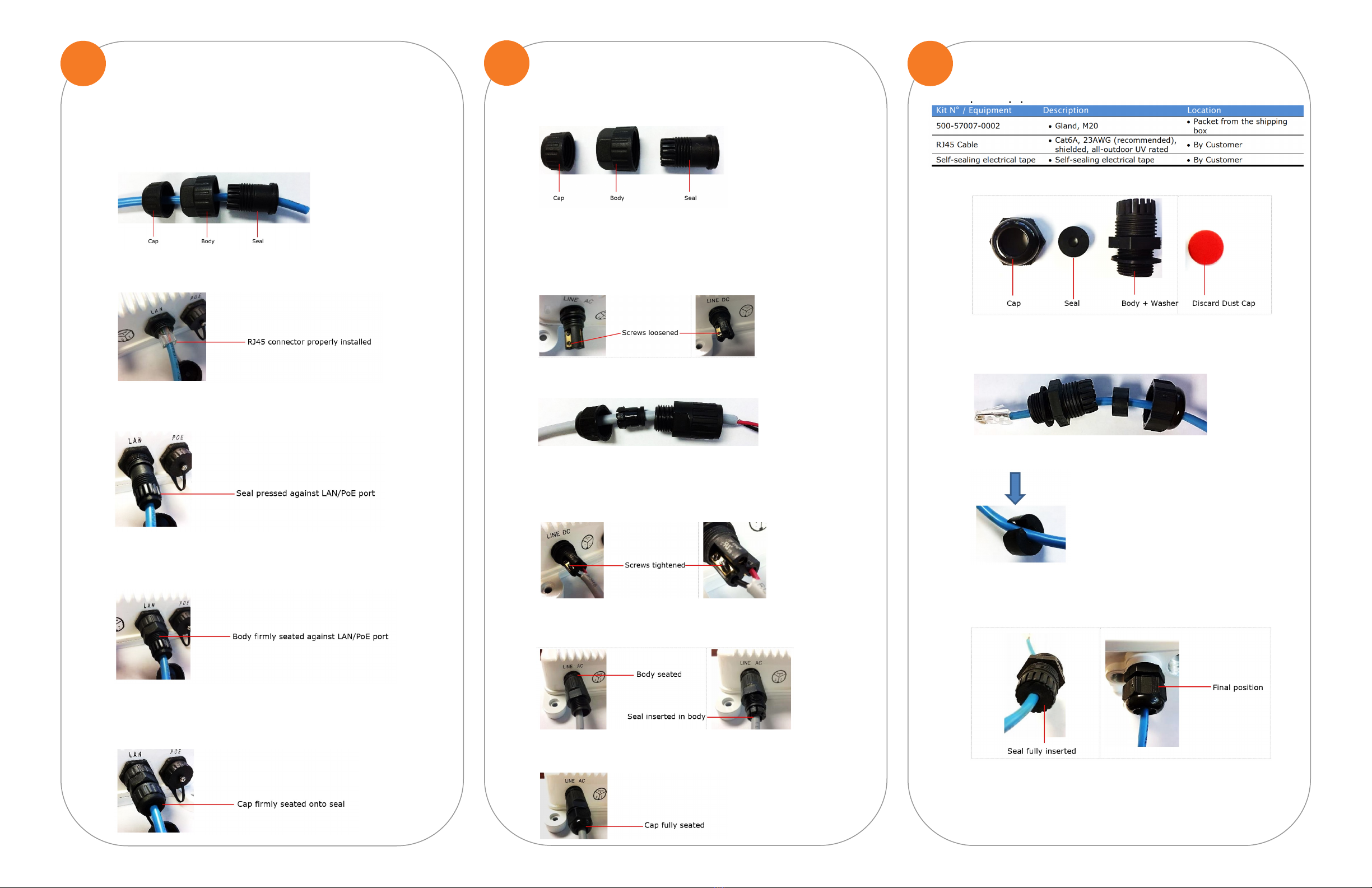
Click on Link Management and then Link Wizard to open the Link Di-
rections window.
Clicking on the number of directions opens the next window where
you are oered the choice of editing the conguration or not.
3. If deciding not to edit this conguration or the one for Link Direction
#2, an Apply window opens.
4. When no further edits to Link Directions are requested, click Submit.
NOTE. Only one direction is available for a Navigator DT model that
includes a built-in coupler or OMT. Navigator DT radios that include two
antenna ports may be one-directional or bi-directional (e.g. repeater
conguration).
Navigator ST radios are always one-directional.
18
Following the antenna manufacturer’s instructions, adjust the azimuth
and elevation of the antenna.
Use the calculated RSL obtained during the link budget process to de-
termine the target RSL voltage.
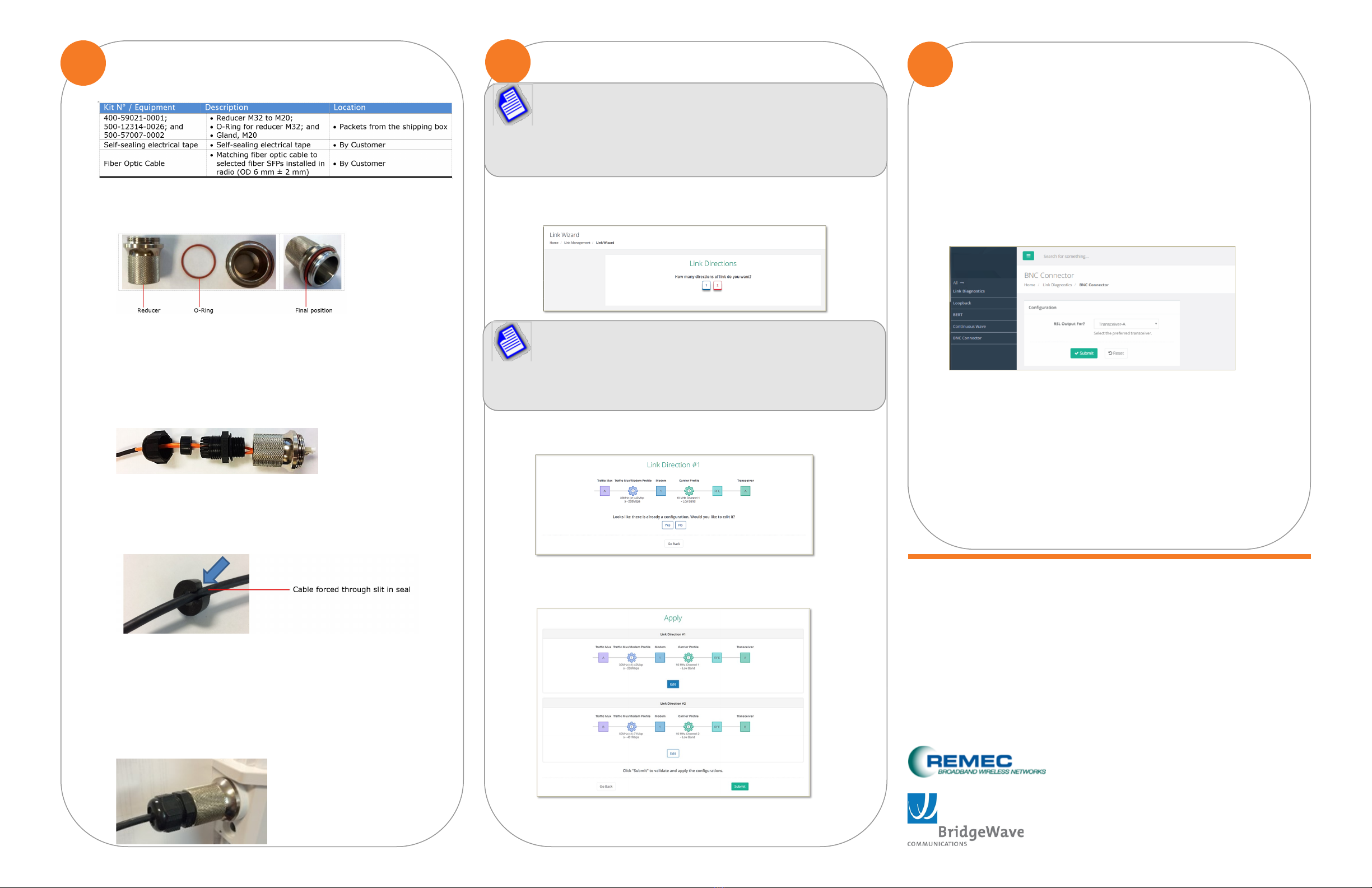
By default, the measured RSL will show the RSL for Transceiver A. For
the Navigator DT dual transceiver radio, the RSL source may be
changed to Transceiver B through a GUI command under Link Diagnos-
tics –> BNC Connector.
Setting the voltmeter to read a 0–10 voltage range (and turning o the
Auto-Range feature, if applicable) will assist in reading the RSL.
Measure the RSL at the Navigator radio’s RSL port. The RSL follows a
typical monotonic response:
RSL (dBm) = -10 VBNC
[e.g. 2.0 VDC @ RSL = -20 dBm, 9.0 VDC @ -90 dBm]
6. Fine-align the antenna following the antenna manufacturer’s instruc-
tions to achieve the desired RSL.
REMEC Broadband Wireless Networks /
BridgeWave Communications
17034 Camino San Bernardo
San Diego, CA 92127 USA
www.BridgeWave.com
16
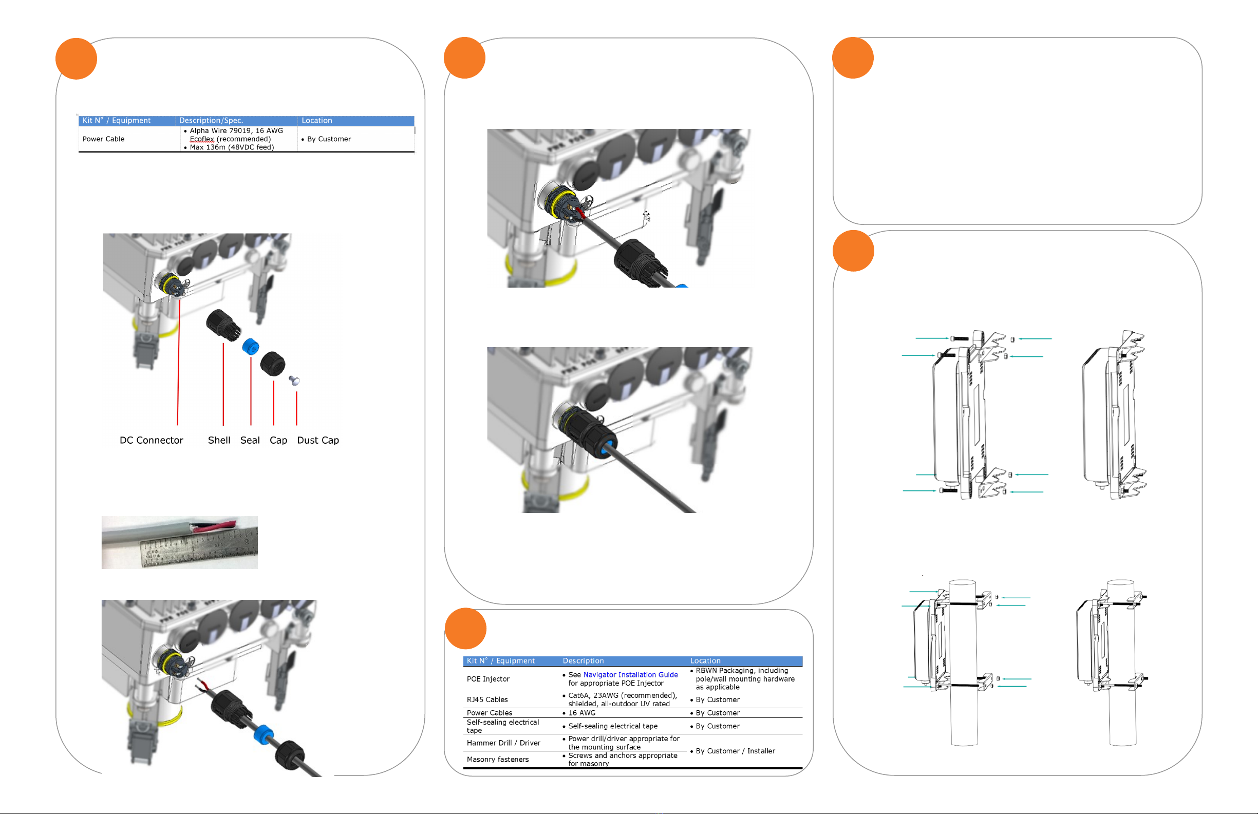
From packets 400-59021-0001 and 500-12314-0026, slide the O-Ring on-
to the reducer.
From packet 500-57007-0002, disassemble Gland M20. Discard the red
dust cap.
Use a ber optic cable matching the ordered SFP. Thread the ber op-
tic cable through all components of Gland M20 (cap, seal, body and
washer), and the reducer.The gland seal’s clamping range is 6 mm ± 2
mm.
For properly inserting the cable through the seal, push the cable
through the slit in the seal as illustrated below. The seal, in its nal po-
sition, must be located over the external sheathing of the ber cable.
Once the SFP module is installed in the radio, insert the ber optic ca-
ble’s end in the radio’s SFP port until hearing a click.
Screw-in the reducer with O-Ring onto the Radio until rmly seated.
Screw-in the body and washer onto the reducer until rmly seated.
Slide the seal into the body, then tighten the cap onto the body until
rmly seated. Wrap the nal assembly in self-sealing tape.
Required Equipment
SFP PORT CONNECTION TO RADIO CONFIGURING THE RADIO - BASIC APPROACH ANTENNA ALIGNMENT
NOTE. Default IP addresses and login credentials for the radios:
Low Band Radio IP address: 192.168.0.1
High Band Radio IP address: 192.168.0.2
Username: admin
Password: adminpass
This manual suits for next models
2