8 9
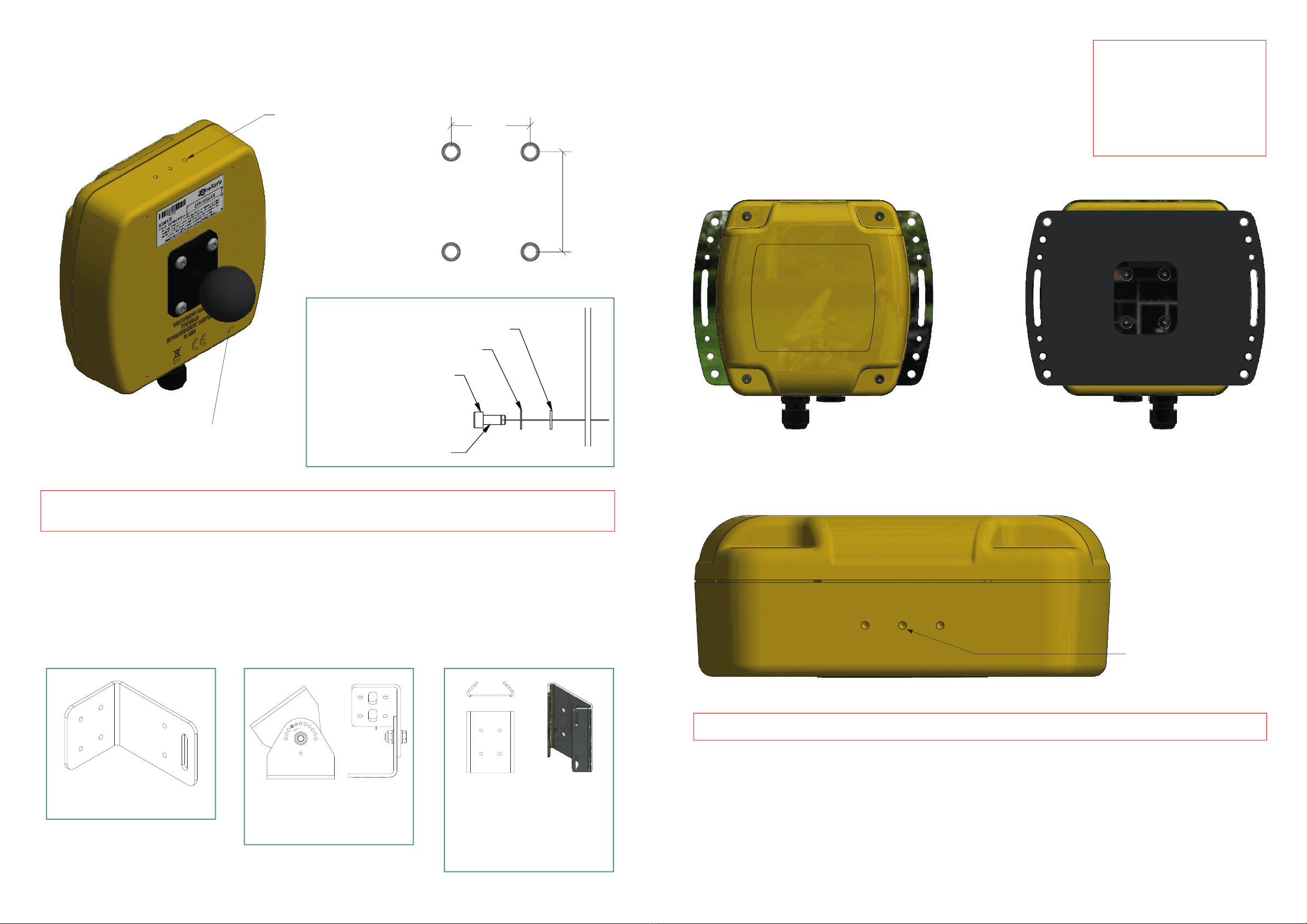
4.3 Additional Brackets
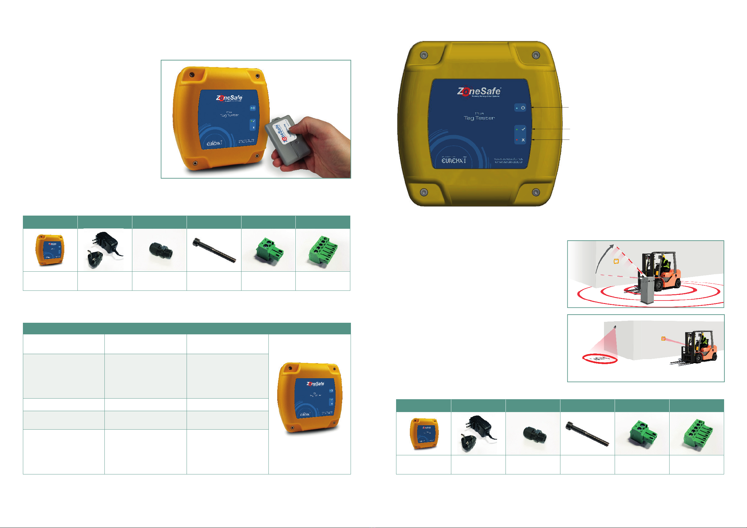
All ZoneSafe units come installed with four M5 threaded inserts in the AMPS hole pattern on the back. These can be
xedtodirectly,adapterplatescanbettedtothebackoftheunits,RAMmountscanbeusedandwealsohavea
rangeofadditionalbracketsallofwhichhavetheAMPSholeconguration.
1
123456
A
B
C
D
E
F
REV: DATE: CHANGE:
STATUS:
CUSTOMER:
SCALE @
DRAWN BY:
REV:
DRAWING NO:
TITLE:
UNCONTROLLED
AVONWOOD INTERNAL
PIVOTLOC
BRACKET SHARED
IMAGES
AS SHOWN
SHEET
N/A
A
A0
THIS DRAWING IS TH EP ROPERTY OF AND MAY EM BODY PROPRIETARY INFO RMATION
OWNED BY AVO NWOOD DEVELOPMENT SL TD. IT IS PROVIDED UND ER A CONFIDENTIAL
RELATIONSHIP FOR A SP ECIFIC PURPOSE. THE RECIPI ENT AGREES TO USE IT ONLY FOR
SUCH PURPOSE.
MH
AS INDICATED IN ISO 2768-1
TOLERANCE CLASS
LINEAR = f
ANGULAR = f
BROKEN EDGES = f
1 / 1
UNLESS OTHERWISE STATED
EXPLODED VIEW
02 7125 - PIN BRACKET
BOLT
WASHER
NUT
WASHER
02 7124 - PLAIN BRACKET
UNLOCK
ROTATE TO NEW POSITION
LOCK POSITION
LOCK PIN
BUTTON HEAD M5X12
M5 SHAKEPROOF
M5 PLAIN WASHER
MAX TORQUE 1.6Nm
15.0015.0020.0015.0015.00
10.00
30.00
38.00
5.80
80.00
58.00
HOLE POSITIONS
AND DIMENSIONS
OVERALL DIMENSIONS
80.00
96.00
68.90
1
1 2 3 4 56
A
B
C
D
E
F
REV: DATE: CHANGE:
STATUS:
CUSTOMER:
SCALE @
DRAWN BY:
REV:
DRAWING NO:
TITLE:
UNCONTROLLED
POLE MOUNT
BRACKET IMAGES
SHEET
A2
THIS DRAWING IS THE PROPE RTY OF AND MAY EMBODY PROPRIET ARY INFORMATION
OWNED BY AVONWOOD DEVELOP MENTS LTD. IT IS PROVID ED UNDER A CONFIDENT IAL
RELATIONSHIP FOR A SPECIFIC P URPOSE. THE RECI PIENT AGREES TO USE IT ONLY FOR
SUCH PURPOSE.
AS INDICATED IN ISO 2768-1
TOLERANCE CLASS
LINEAR = f
ANGULAR = f
BROKEN EDGES = f
1 / 1
UNLESS OTHERWISE STATED
100.00
77.00
40.23
24.75
19.50
1
1 2 3 4 56
A
B
C
D
E
F
REV: DATE: CHANGE:
STATUS:
CUSTOMER:
SCALE @
DRAWN BY:
REV:
DRAWING NO:
TITLE:
UNCONTROLLED
POLE MOUNT
BRACKET IMAGES
SHEET
A2
THIS DRAWING IS TH EPR OPERTY OF AND MAY EM BODY PROPRIETARY INFOR MATION
OWNED BY AVONWO OD DEVELOPMENTS LT D. IT IS PROVIDED UNDE R A CONFIDENTIAL
RELATIONSHIP F OR A SPECIFIC PUR POSE. THE RECIPI ENT AGREES TO U SE IT ONLY FOR
SUCH PURPOSE.
AS INDICATED IN ISO 2768-1
TOLERANCE CLASS
LINEAR = f
ANGULAR = f
BROKEN EDGES = f
1 / 1
UNLESS OTHERWISE STATED
100.00
77.00
40.23
24.75
19.50
The PivotLoc Bracket which
canberotatedandlockedo
in one of 11 angled positions.
The Pole Mount Bracket can be
used on poles with a diameter
of between 50-100mm with
the use of worm drive hose
clamps x2 or zip / cable ties
(not included).
1
123456
A
B
C
D
E
F
REV: DATE: CHANGE:
STATUS:
CUSTOMER:
SCALE @
DRAWN BY:
REV:
DRAWING NO:
TITLE:
UNCONTROLLED
AVONWOOD INTERNAL
PIVOTLOC
BRACKET SHARED
IMAGES
AS SHOWN
SHEET
N/A
A
A0
THIS DRAWING IS TH EP ROPERTY OF AND MAY EM BODY PROPRIETARY INFO RMATION
OWNED BY AVO NWOOD DEVELOPMENT SL TD. IT IS PROVIDED UND ER A CONFIDENTIAL
RELATIONSHIP FOR A SP ECIFIC PURPOSE. THE RECIPI ENT AGREES TO USE IT ONLY FOR
SUCH PURPOSE.
MH
AS INDICATED IN ISO 2768-1
TOLERANCE CLASS
LINEAR = f
ANGULAR = f
BROKEN EDGES = f
1 / 1
UNLESS OTHERWISE STATED
EXPLODED VIEW
02 7125 - PIN BRACKET
BOLT
WASHER
NUT
WASHER
02 7124 - PLAIN BRACKET
UNLOCK
ROTATE TO NEW POSITION
LOCK POSITION
LOCK PIN
BUTTON HEAD M5X12
M5 SHAKEPROOF
M5 PLAIN WASHER
MAX TORQUE 1.6Nm
15.0015.0020.0015.0015.00
10.00
30.00
38.00
5.80
80.00
58.00
HOLE POSITIONS
AND DIMENSIONS
OVERALL DIMENSIONS
80.00
96.00
68.90
Right Angle Mounting Bracket.
1
123456
A
B
C
D
E
F
REV: DATE: CHANGE:
STATUS:
CUSTOMER:
SCALE @
DRAWN BY:
REV:
DRAWING NO:
TITLE:
UNCONTROLLED
SHEET
A3
THIS DRAWING IS T HE PROPERTY OF AND MAY EMBODY PROPRIE TARY INFORMATION
OWNED BY AVON WOOD DEVELOPMENTS LTD. IT IS PROVI DED UNDER A CONFIDEN TIAL
RELATIONSHIP FO RA SPECIFIC PURPOSE . THE RECIPIENT AGREES TO USE IT ON LY FOR
SUCH PURPOSE.
AS INDICATED IN ISO 2768-1
TOLERANCE CLASS
LINEAR = f
ANGULAR = f
BROKEN EDGES = f
1 / 1
UNLESS OTHERWISE STATED
4.4 Adaptor plates
An adaptor plate is available for all the units. These attach via four
countersunk M5 nylon patched screws.
The plate provides slots and holes on the sides, it is rubber backed to
prevent scratching. Two of these plates can be bolted back to back to
clamp between vertical fence railing, the rubber backing helping to grip
in place.
1
1 2 3 4 56
A
B
C
D
E
F
REV: DATE: CHANGE:
STATUS:
CUSTOMER:
SCALE @
DRAWN BY:
REV:
DRAWING NO:
TITLE:
UNCONTROLLED
SHEET
A2
THIS DRAW ING IS TH E PROPERTY OF AND MAY EMBODY PROP RIETARY IN FORMATIO N
OWNED BY AVONWO OD DEVELO PMENTS LTD. IT IS PRO VIDED UN DER A CONF IDENTIAL
RELATION SHIP F OR A SPEC IFIC PUR POSE. THE RECIPI ENT AGRE ES TO U SE IT ONLY FOR
SUCH PURPOSE.
AS INDICATED IN ISO 2768-1
TOLERANCE CLASS
LINEAR = f
ANGULAR = f
BROKEN EDGES = f
1 / 1
UNLESS OTHERWISE STATED
4.00
3.00
RUBBER BACK
ALUMINIUM PLATE
6.60
5.50
4.50
40.00
5.50
VARIOUS FIXING HOLES AND SLOT
COUNTER SUNK ATTACHMENT HOLES
IN THE AMPS PATTERN.
138.00
190.00
AdaptorPlatettedtothePlusenclosure
• AlternativelyusetheAMPSholecongurationforRAMMountFixtures,use1.5”ballttings.
• BackxwiththefourAMPSholestosuityourapplication.
• Shake-proof washers are recommended and thread locking liquid can also be used.
VIEW A-A
SCALE 1 : 1
SECTION C-C
SCALE 1 : 1
A
C
C
1
123456
A
B
C
D
E
F
REV: DATE: CHANGE:
STATUS:
CUSTOMER:
SCALE @
DRAWN BY:
REV:
DRAWING NO:
TITLE:
UNCONTROLLED
SHEET
A0
THIS DRAW ING IS THE PROPE RTY OF AND MA Y EMBODY PROPR IETARY INFO RMATION
OWNED B Y AVONWOOD DEV ELOPMENTS L TD. IT IS PROV IDED UNDER A CONF IDENTIAL
RELATION SHIP FOR A SPECIF IC PURPOSE. THE RE CIPIENT AGREES TO U SE IT ONLY FOR
SUCH PUR POSE.
AS INDICATED IN ISO 2768-1
TOLERANCE CLASS
LINEAR = f
ANGULAR = f
BROKEN EDGES = f
1 / 1
UNLESS OTHERWISE STATED
POWER INDICATOR
DRILL POINT
DRILL POINT
DRILL POINT
DRILL POINT
AMPS
POWER INDICATOR
READ INDICATOR
155.00
155.00
60.00
GOOD BATTERY
BAD BATTERY
28.00
14.00 14.00
DETAIL A
SCALE 1 : 1
SECTION B-B
SCALE 2:1
SECTION C-C
SCALE 2:1
VIEW D-D
SCALE 1 :3
A
B B
C C
D
1
123 4 5 6
A
B
C
D
E
F
REV: DATE: CHANGE:
STATUS:
CUSTOMER:
SCALE @
DRAWN BY:
REV:
DRAWING NO:
TITLE:
UNCONTROLLED
SHEET
A1
THIS DRAWING IS THE PROPERTY OF AND MAY EMBODY PROPRIETAR Y INFOR MATION
OWNED BY AVONWOOD DEVELOPMENTS LTD. IT IS PROVIDED UNDER A CONFIDENTIAL
RELATIONSHIP FO R A SPECIFIC PURPOSE. THE RECIPIENT AGREES TO USE IT ONLY FOR
SUCH PURPOSE.
AS INDICATED IN ISO 2768-1
TOLERANCE CLASS
LINEAR = f
ANGULAR = f
BROKEN EDGES = f
1 / 1
UNLESS OTHERWISE STATED
30.00
38.00
3.00
7.40
12.00
1.60
5.40
3.00
1.60
10.00
M5 X 0.8mm PITCH
M5 INT TOOTH SHAKEPROOF
M5 PLAIN
FIXTURE
0.00
200mm
200.00
38.00
30.00
AMPS HOLE
CONFIGURATION
DETAIL A
SCALE 1 : 1
SECTION B-B
SCALE 2:1
SECTION C-C
SCALE 2:1
VIEW D-D
SCALE 1 :3
A
B B
C C
D
1
123 4 5 6
A
B
C
D
E
F
REV: DATE: CHANGE:
STATUS:
CUSTOMER:
SCALE @
DRAWN BY:
REV:
DRAWING NO:
TITLE:
UNCONTROLLED
SHEET
A1
THIS DRAWING IS THE PROPERTY OF AND MAY EMBODY PROPRIETARY INFORMATION
OWNED BY AVONWOOD DEVELOPMENTS LTD. IT IS PROVIDED UNDER A CONFIDENTIAL
RELATIONSHIP FOR A SPECIFIC PURPOSE. THE RECIPIENT AGREES TO USE IT ONLY FOR
SUCH PURPOSE.
AS INDICATED IN ISO 2768-1
TOLERANCE CLASS
LINEAR = f
ANGULAR = f
BROKEN EDGES = f
1 / 1
UNLESS OTHERWISE STATED
30.00
38.00
3.00
7.40
12.00
1.60
5.40
3.00
1.60
10.00
M5 X 0.8mm PITCH
M5 INT TOOTH SHAKEPROOF
M5 PLAIN
FIXTURE
0.00
200mm
200.00
THREAD LOCK
M5 PLAIN
M5 INT TOOTH SHAKE-PROOF
M5 X 0.8mm PITCH
THREAD LOCK
RAM Mount Ball
Base Fixing Option
(examplexingnotincluded)
DRILL POINTS
Drill marks
VIEW A-A
SCALE 1 : 1
SECTION C-C
SCALE 1 : 1
A
C
C
1
123456
A
B
C
D
E
F
REV: DATE: CHANGE:
STATUS:
CUSTOMER:
SCALE @
DRAWN BY:
REV:
DRAWING NO:
TITLE:
UNCONTROLLED
SHEET
A0
THIS DRAWING IS THE PROPER TY OF AND MAY EMBODY PROPRIETARY INFORMATION
OWNED BY AVONWOOD DEVELOPMENTS LTD. IT IS PROVIDED UNDER A CONF IDENTIAL
RELATIONSHIP FOR A SPECIF IC PURPOSE. THE RECIPIENT AGR EES TO USE IT ONLY FOR
SUCH PURPOSE.
AS INDICATED IN ISO 2768-1
TOLERANCE CLASS
LINEAR = f
ANGULAR = f
BROKEN EDGES = f
1 / 1
UNLESS OTHERWISE STATED
POWER INDICATOR
DRILL POINT
DRILL POINT
DRILL POINT
DRILL POINT
AMPS
POWER INDICATOR
READ INDICATOR
155.00
155.00
60.00
GOOD BATTERY
BAD BATTERY
28.00
14.00 14.00
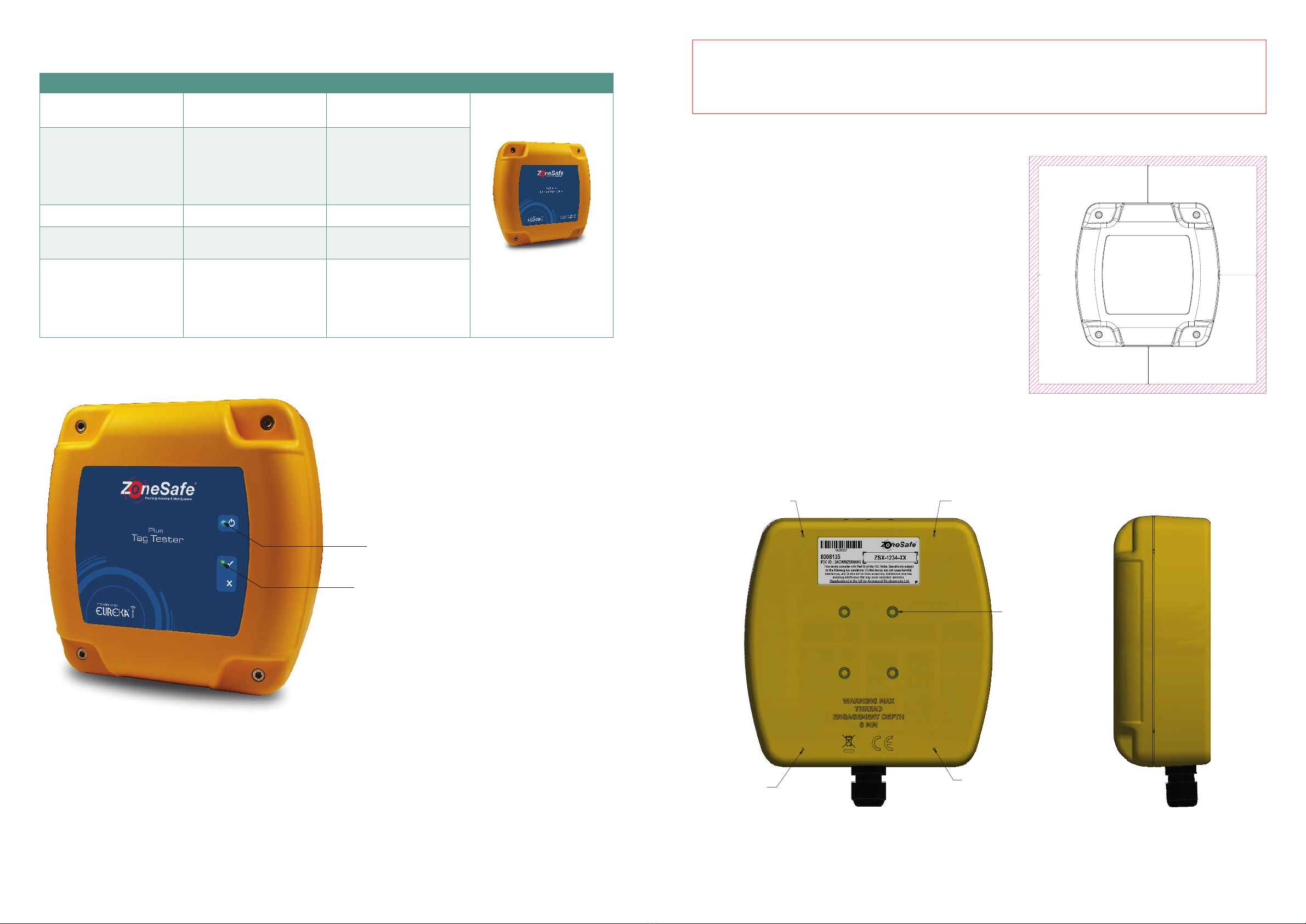
4.5 Cable Entry
• Supply24VDC+/-5%10WorusethePoweroverEthernet(PoEdaughterboardmoduleneeded-seepage12).
Use a suitable Cat5e data cable to connect comms.
• Runpoweranddataintoyourdeviceusingwaterproofcableglands,(Max16mmDiameter)orinternallythreaded
conduit (Max 20mm diameter). Only use the central drill point as indicated above.
• Holes can be made by drilling through one of the marked locations on the box.
• ForanIP67applicationuseratedglandsorenterthroughtheundersidewith suitably sealed conduit. Entry through
the back is possible but if ingress protection is needed then the entry hole must be suitably sealed.
NOTE:
Please make a note of the
serial number located on
the back of the device. You
will need this to set up and
connect to the network.
CENTRAL
DRILL POINT
PivotLoc Bracket Kit - ZSM7154-A Pole Mount Bracket Kit - ZSM7154-BRight Angle Bracket Kit - ZSM7154-C
P/NZSM6908-E
NOTE : Care should be taken when drilling holes through enclosure.
THE MAXIMUM THREAD ENGAGEMENT DEPTH OF 8MM MUST NOT BE EXCEEDED