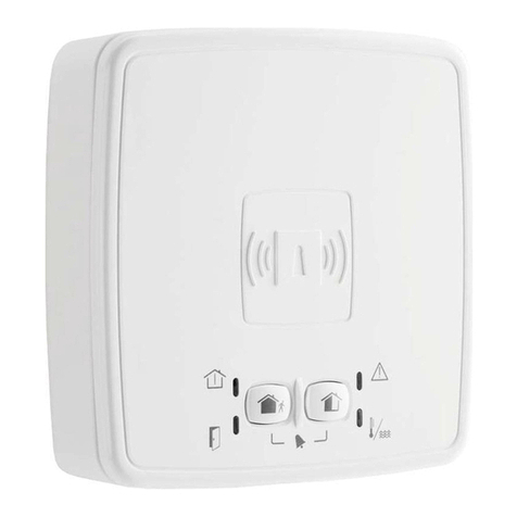
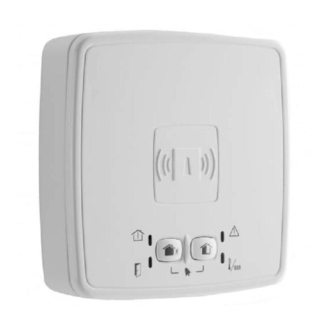
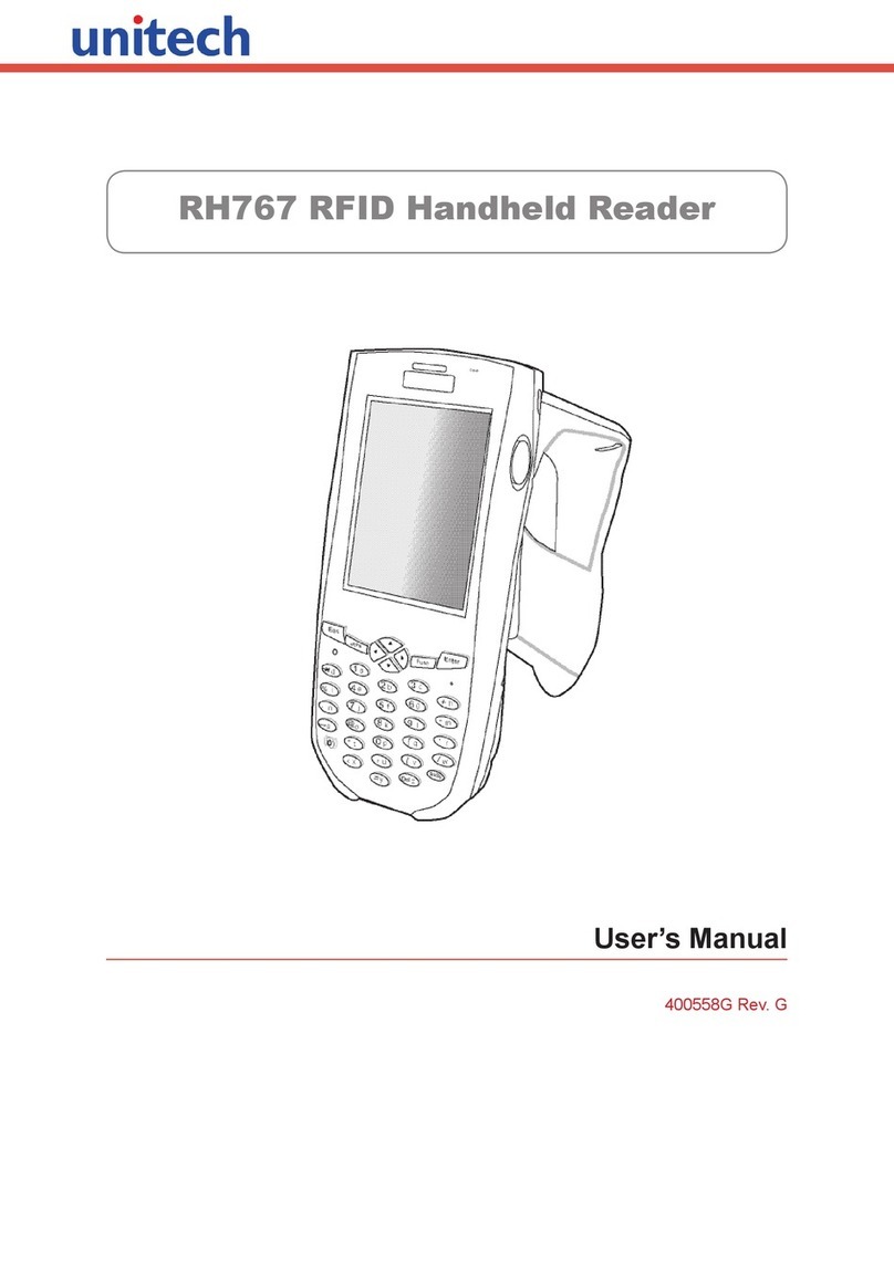
Honeywell 026366.00 User manual

Achtung!
Vor dem Öffnen des Lesers muss das Gerät spannungslos
geschaltet werden. Im gekennzeichneten Instandhaltungs-
bereich liegen gefährliche Spannungen an.
Der Leser darf nur mit einer Spannung von 11 bis 15 V DC
betrieben werden.
Der Leser kann Stromaufnahme erreichen.
Adernquerschnitt beachten (z. B. ACS-8 Installationsanleitung,
Berechnungsbeispiele).
Für den Anschluss des Lesers 026366.10 an die Zentrale muss
ein geschirmtes Kabel verwendet werden. Der Schirm muss am
Leser an der Schirmklemme (KL1) und in der Zentrale an der
dafür vorgesehenen Klemme angeschlossen werden.
Zwischen berührungslosen Lesern muss ein Mindestabstand
von 3m in allen Richtungen eingehalten werden.
bis zu 450 mA
Der Leser darf nicht direkt auf Metall montiert werden. Die
Lesedistanz würde stark vermindert werden.
Direkte Sonneneinstrahlung vermeiden.
Der Leser darf keinen kunststoffzersetzenden Lösungs-
mitteldämpfen ausgesetzt werden.
Montagehinweise
Bei Verwendung von Schlüsselanhängern kann sich die Reichweite
verringern.
**
Technische Daten
Betriebsnennspannung
Betriebsspannungsbereich
Schnittstelle 026366.10
Stromaufnahme
Schutzart
Sendefrequenz
Betriebstemperaturbereich
Umweltklasse gemäß VdS
Lesereichweite
Farbe Gehäuse
Farbe Folie
Schnittstelle 026366.00
12V DC
11V DC bis 15V DC
Clock/Data und RS 485
400mA + 12mA/LED
IP 40
125kHz
-25°C bis +60°C
III*
ca. 25cm**
grauweiß (ähnlich RAL 9002)
lichtgrau (ähnlich RAL 7035)
Clock/Data
Bestückungsplan Art.-Nr. 026366.00
ST16
ST18
Bestückungsplan Art.-Nr. 026366.10
1
Deckelkontakt
8
Montage- und Bedienungsanleitung
Berührungsloser Leser, aP
Art.-Nr.026366.00 / 026366.10
Änderungen
vorbehalten
P30704-45-002-00
2008-10-01 D
* Mit Tropfwasserschutz, sonst Klasse II
ST16
ST18
1
71
4
ST1
Deckelkontakt
Nur bei 026366.10
Abschlusswiderstände
ST3
ST2
KL1 = Schirmklemme
Achtung!
Gefährliche
Spannungen
Achtung!
Gefährliche
Spannungen
GB
Das Gerät entspricht bei bestimmungsgemäßer
Anwendung den grundlegenden Anforderungen
gemäßArtikel 3 der R&TTE-Richtlinie 1999/5/EG.
Die EG-Konformitätserklärung steht auf unserer
Homepage zum Download bereit.
Adressen
019200
9600
Baud
1
6
DIP-Schalter
Baudrate
00 -
Clock/Data
RS 485
-
11
Leserart
0
7
8
DIP-Schalter
01
1
Leserart
Bei Clock/Data-Betrieb
werden die DIP-Schalter
1-6 in Stellung "0" gestellt.
DIP-Schalter-Stellungen 026366.10
1
2
3
4
5
6
7
8
9
31
32
Adresse
DIP-Schalter
0
0
0
0
0
0
0
0
1
5
0
0
0
1
1
0
0
0
0
1
4
0
0
0
1
1
1
0
0
1
1
3
0
1
1
0
0
0
1
1
1
1
1
0
0
1
1
1
0
0
0
000 00
0
1
2
1
** RS485EN darf nur verwendet werden, wenn der Leser über
ein Potentialtrennungsmodul am ACS-8 angeschlossen wird
(siehe Anschlusspläne ACS-8 und Potentialtrennungsmodul).
In allen anderen Fällen darf dieser Draht nicht angeschlossen
werden.Die Garantie erlischt bei falscher Verdrahtung, da das
Gerät dadurch beschädigt oder zerstört werden kann.
Signalname
Clock
GND
+12V DC
LED rot
LED gelb
LED grün
frei
Data
026366.00
ST16
1
2
3
4
5
6
7
8
Signalname
Clock
GND
+12V DC
LED rot
LED gelb
LED grün
Data
Anschlussbelegung
ST16
1
2
3
4
5
6
7
026366.10
1 0V RS485
2 D
3 D*
4 RS48EN**
ST1 Signalname
Gerät bitte nicht mit scharfkantigen Gegenständen bedienen! Vorsicht
mit Fingernägeln, Ringen etc. Zur Bedienung nur leicht berühren.
Zum Reinigen keine ätzenden oder Kunststoff zersetzende Flüssigkei-
ten wie Benzin, Terpentin, Nitro etc. verwenden.
Keine Reinigungsmittel verwenden, die auf mechanischer Basis
wirken, z. B. Scheuermilch, Scheuerschwamm etc.
Reinigung mit weichem, feuchten Tuch. Nur klares Wasser verwen-
den.
Scharfe Reinigungsmittel können die Oberflächen beschädigen oder
verfärben.
Pflegehinweise
Anschlusspläne finden Sie in den Dokumentationen der jeweiligen ZK-
Zentralen.
Bedeutung der LEDs bei ZK-Anwendungen:
LED- Grund- Nach Lesung Bedeutung
farbe zustand einer Karte
gelb an Betrieb / lesebereit
gelb aus Gerät ist spannungslos
PIN-Code- oder Türcode-
eingabe ist aktiv
(nur bei Lesern mit RS-485
Schnittstelle möglich)
grün an Dauerfreigabe
rot an Dauersperrung
grün an Türfreigabe
rot an Ausweis nicht berechtigt
rot blinkend Lesefehler
Es gelten zusätzlich die Tasten- und LED-Funktionen der
Macrosteuerung von IQ MultiAccess (siehe separate Anleitung
"Weiterführende Funktionen zu IQ MultiAccess", P32205-46-000-xx).
Bedeutung der LEDs
Honeywell Security & Data Collection
Novar GmbH
Johannes-Mauthe-Straße 14
D-72458 Albstadt
www.honeywell.com/security/de
146
121
172
200
40
16
13
Abmessungen (in mm)
P30704-45-002-00
2008-10-01
© 2008 Novar GmbH
gelb
grün
rot

Connections
By using the ID keyfob the read distance is reduced.
**
Technical data
Rated operating voltage
Operating voltage range
Interface 026366.10
Current consumption
Protection category
Transmitting frequency
Operation temperature range
environmental class in acc. with VdS
Read distance
Colour case
Colour foil
Interface 026366.00
12V DC
11V DC up to 15V DC
clock/data and RS 485
400mA + 12mA/LED
IP40
125kHz
-25°C up to +60°C
III*
ca. 25cm**
grey-white (similar to RAL 9002)
light-grey (similar to RAL 7035)
clock/data
ST16
1
2
3
4
5
6
7
8
signal name
clock
GND
+12V DC
LED red
LED yellow
LED green
free
data
026366.00
ST16
1
2
3
4
5
6
7
signal name
Clock
GND
+12V DC
LED rot
LED gelb
LED grün
Data
026366.10
ST1 signal name
1 0V RS485
2 D
3 D*
4 RS485EN**
* Drip-proof, otherwise class II
Address
019200
9600
Baud rate
1
6
DIP-switch
Baud rate
00 -
Clock/Data
RS 485
-
11
Reader
mode
0
7
8
DIP-switch
01
1
Reader mode
In clock/data mode the
DIP-switch 1-6 must be
in position "0".
DIP-Switches 026366.10
1
2
3
4
5
6
7
8
9
31
32
Address
DIP-switch
0
0
0
0
0
0
0
0
1
5
0
0
0
1
1
0
0
0
0
1
4
0
0
0
1
1
1
0
0
1
1
3
0
1
1
0
0
0
1
1
1
1
1
0
0
1
1
1
0
0
0
000 00
0
1
2
1
Component diagram item no. 026366.10
Component diagram item no. 026366.00
ST16
ST18
1
cover contact
8
ST16
ST18
1
71
4
ST1
Cover contact
ST3
ST2
only 026366.10
Terminating resistors
Attention!
High Voltage
Attention!
High Voltage
KL1 = shield terminal
DGB Subject to change
without notice
Mounting and Operation Instructions
Contactless reader, s. m.
Item no. 026366.00 / 026366.10
Mounting / Connection Informations
Before opening the reader the device must be de-energized.
The reader is only allowed to be operated with a voltage from 11
to 15 V DC.
The reader can reach a current consumption of up to 450 mA.
The cable cross section (e. g. ACS-8
installation manual, calculation examples).
Use a shielded cable when connecting the reader 026366.10 to
a central unit. Connect the shielding to terminal KL1 of the
reader and to the corresponding terminal of the central unit.
Attention!
must be observed
Between contactless readers must be a minimum distance
of 3 m in all directions.
Do not install the reader directly on metal as this would
considerably reduce the reading distance.
Avoid direct sun rays.
The reader should not be exposed to plastic decomposing
solvent vapours.
The device complies with the essential requirements of
the R&TTE 1999/5/EC Directive, if used for its intended
use. The EC-Declaration of Conformity can be
downloaded from our homepage (Service / Download).
** RS485EN may only be used, if the reader is connected to an
ACS-8 via a potential isolation module (see connection
diagrams of ACS-8 and potential isolation module). In all other
cases this cable must not be connected. The guarantee expires
with wrong wiring, as the device might be damaged or
destroyed.
P30704-45-002-00
2008-10-01

Using the device correctly
Tap the device lightly with fingertips. Never strike or apply strong
pressure to the device.
The use of hard or sharp objects, including fingernails, rings, etc. can
cause scratches and damage the device.
Wipe the device with a dry soft lint-free cloth, or one that has
been lightly dampened with water.
The use of caustic liquids such as benzene, thinners, alcohol, solvents,
or abrasive cleaners of any kind will lead to surface deterioration and
damage.
To clean:
Honeywell Security & Data Collection
Novar GmbH
Johannes-Mauthe-Straße 14
D-72458 Albstadt
www.honeywell.com/security/de
P30704-45-002-00
2008-10-01
© 2008 Novar GmbH
Connection diagrams can be found in the documentations of the
correspondingAC controllers.
LED meaning withAC applications:
LED Basic After reading Meaning
colour condition a card
yellow on Operation / ready to read
off Device is idle
PIN-Code or door code
entry is active
(only possible with readers
with RS-485 interface)
green on Permanently released
red on Permanently blocked
green on Door release
red on ID card not authorized
red blinking Read error
yellow
Additionally, the key and LED functions of the macro control of IQ
MultiAccess are valid (see separate manual "Supplementary functions
of IQ MultiAccess", P32205-46-0G0-xx).
Meaning of LEDs
146
121
172
200
40
16
13
Dimensions (in mm)
yellow
green
red
This manual suits for next models
1
Table of contents
Languages:
Other Honeywell RFID System manuals

Honeywell
Honeywell ARC-X User manual

Honeywell
Honeywell IM11-PRT User manual

Honeywell
Honeywell IF1C User manual

Honeywell
Honeywell IH45 User manual

Honeywell
Honeywell Connected Home SPR-S8EZS User manual

Honeywell
Honeywell Home SPR-S8EZS User manual

Honeywell
Honeywell IH40 User manual

Honeywell
Honeywell IH25 User manual

Honeywell
Honeywell IH25 User manual

Honeywell
Honeywell IH25 User manual