2LenelS2 Readers - 5000 Series
Slimline Economy 13.56 MHz
- Technical specifications
Operating frequency 13.56 MHz.
Reading technologies
MIFARE® CSN 4 byte, MIFARE® CSN 7 byte, MIFARE Classic®, MIFARE Plus,
MIFARE® DESFire® 0.6, MIFARE DESFire EV1, MIFARE DESFire EV2**, MIFARE
DESFire EV3**. Also supports other ISO 14443 A/B* compatible cards.
*Not all ISO14443 B cards have been implemented in the reader, please
contact LenelS2 for more details on current status. MIFARE is a registered
trademark of NXP B.V. and is used under license. **Application coding must be in
accordance with EV1.
Communication protocols Wiegand, RS232
RS485 converter : OSDP 1, OSDP 2 (including secure channel), RS485
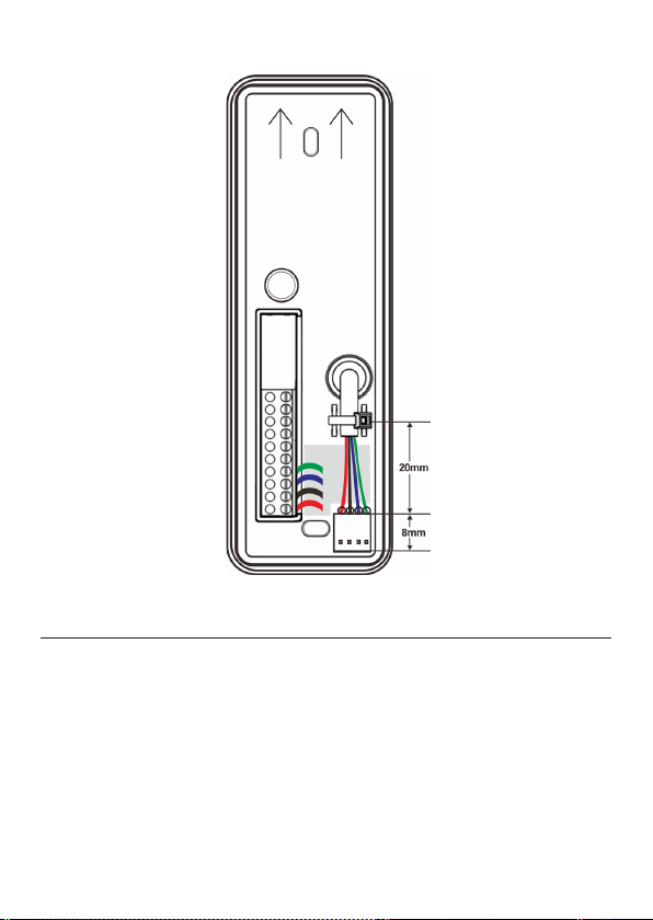
OSDP / RS485 converter
connector Supports a wire diameter from 20 to 24 AWG. Requires twisted pair cable.
Reading output format 24 to 64 (excluding parity bits).
Indicators LED, Green, Red and Yellow (Bi-color). Backlight in blue color. Buzzer.
Power supply 9 to 12 VDC
Current consumption
12 VDC, idle mode 35 mA**
Wiegand: 12 VDC, idle mode 35 mA, peak draw 92 mA (LED Bar setting =low,
Backlight setting = low)**
OSDP: 12 VDC, idle mode 46 mA, peak draw 114 mA (LED Bar setting =low,
Backlight setting = low)**
Operating temperature
-20° to +60°C
When installing readers in environments with extreme heat
(above +50°C) it is recommended to utilize the climate protection
LNL-R50000-WRW which provides additional shading to the reader.
Operating humidity 0 to 95% RHNC
(Relative Humidity No Condensation)
Ingress Protection
Classification IP65 / IK07
Dimension (W x H x D) 79 x 109 x 25
Configuration Methods Configuration card, reader tool software or factory configured readers.
Compliances
**Current draw differs depending on functionality used and can also be
limited in the reader configuration.
Current draw (idle) is defined as reader connected to power, no LED’s lit,
buzzer is not sounding and no reading of credential or key pressing is processed by
the reader. Current draw (peak) is defined as reader powered with both backlight and
LED frame lit (Yellow), buzzer is sounding and reader is reading a credential
while simultaneously a key pressing is processed.