12 13
Electrical Requirements General Information
Electrical Requirements
Check your local codes regarding this unit.
This cooktop is supplied with a 3-wire, A.C.
208V/120 volt or 120V/240 volt, 60 HZ
electrical system. A white (neutral) is not
needed for this unit. See next section for
grounding instructions. It should be fused
separately.
Refer to the specifications chart for kilowatt
rating and recommended amperage. House
wiring and fusing must comply with local
codes. If no local codes are applicable, wire
in accordance with the National Electrical
Code, ANSI/NFPA 70-latest edition.
WARNING
BURN HAZARD
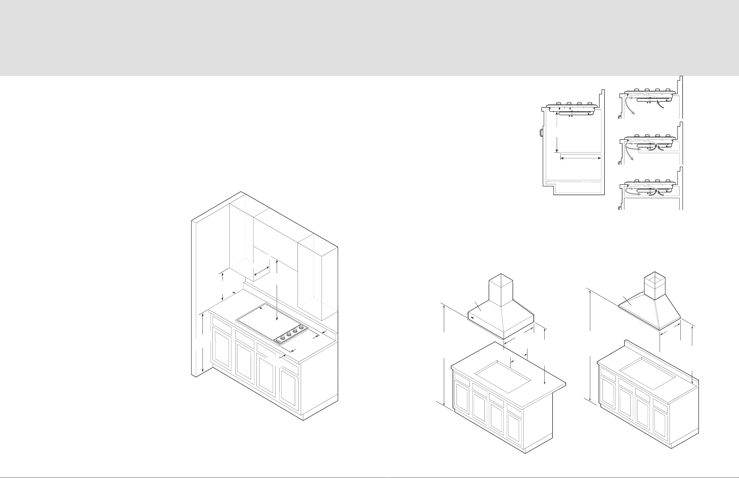
The use of cabinets for storage
above the appliance may result
in potential burn hazard. Combustible
items may ignite, metallic items may
become hot and cause burns. If a cabinet
storage is to provided the risk can be
reduced by installing a range hood that
projects horizontally a minimum of 5" (12.7
cm) beyond the bottom of the cabinets.
Electrical Connection
When making the wire connections, use
the entire length of the conduit provided
(3 feet). The conduit must not be cut.
Connect the red and black leads from the
unit conduit to the corresponding leads in
the junction box. The bare ground wire in the
conduit is connected to the unit frame. When
connecting to a 3-conductor branch circuit,
connect the bare ground connector lead of
the unit to the branch circuit ground (bare
wire or green in color).
WARNING
The electrical power to the
unit must be shut off while line
connections are being made.
Failure to do so could result in serious
injury or death.
WARNING
FIRE AND ELECTRICAL
SHOCK HAZARD
DO NOT use an extension
cord with this appliance. Such
use may result in fire, electrical
shock, or other personal injury.
READ AND FOLLOW ALL WARNING
AND CAUTION INFORMATION WHEN
INSTALLING THIS APPLIANCE.
• Keep appliance area clear and free from
combustible materials, gasoline and other
flammable vapors.
• Disconnect the electrical supply prior to
servicing or cleaning.
• When removing the cooktop for service
and/or cleaning, disconnect AC power
supply.
• Electrical requirements are listed in the
product specifications under the “Electrical
Requirements” section.
12
Ground Green
Black
Red
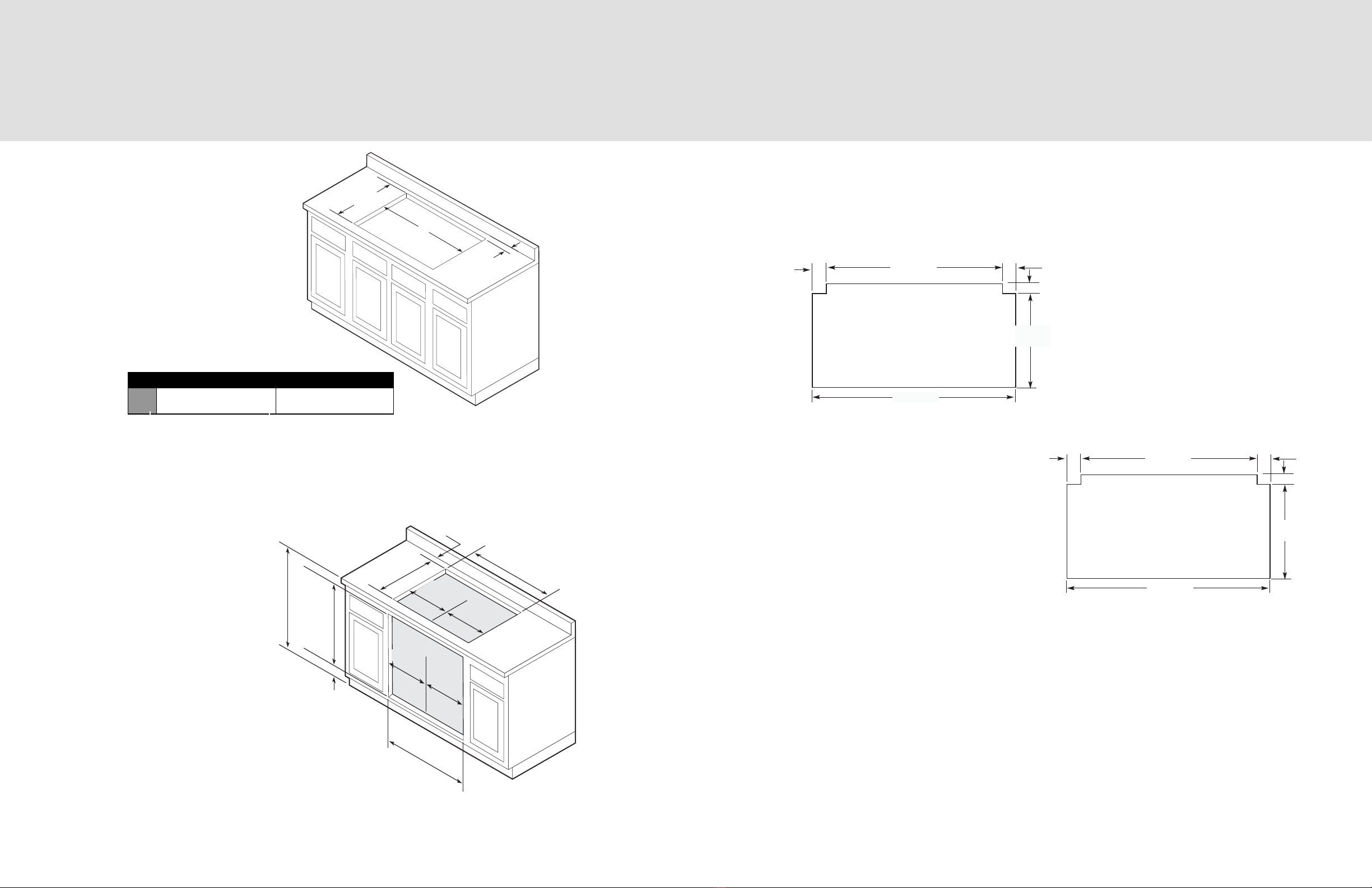
Cooktop
Bracket
Countertop
34
Lower cooktop into cutout. Connect the red and black leads from the unit conduit
to the corresponding leads in the junction box.
Screw brackets to burner box with sheet metal screw.
(Two bracket assemblies included)
Screw sheet metal screws into brackets
and tighten firmly against bottom of countertop.
Note: Be careful not to crack or damage
counter by overtightening.
CAUTION
Be sure the electric power is
off from the breaker box to the
junction box until the cooktop
is installed and ready to operate. The
junction box should be connected to a
suitable ground.
Installation