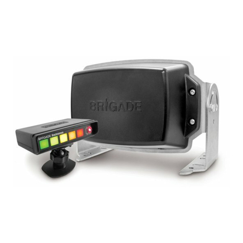
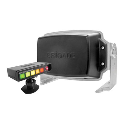
Brigade Backsense BS-9100 Original operating instructions

Installation Guide 7059
BS-9100 / BS-9100T
Backsense®
CAN Radar Object Detection System
Installation & Operation Guide

2
Table of Contents
1Introduction...................................................................................................................... 3
1.1 Detection Range..................................................................................................... 3
1.2 Object Detection Capability..................................................................................... 3
2Contents........................................................................................................................... 6
2.1 Standard System Contents ..................................................................................... 6
2.2 Optional items (not included)................................................................................... 6
3Object Detection............................................................................................................... 7
3.1 Separate Object Detection...................................................................................... 7
3.2 Detected Object Data.............................................................................................. 7
3.3 Detected Object Position Relative to Sensor........................................................... 8
4Hardware Installation........................................................................................................ 9
4.1 Recommended Network Layouts and Limitations.................................................... 9
4.2 Good Network Arrangement.................................................................................... 9
4.3 Bad Network Arrangement.................................................................................... 10
4.4 Test Site ............................................................................................................... 10
4.5 Sensor Mounting and Location.............................................................................. 11
4.6 Sensor Direction ................................................................................................... 12
4.7 Cable.................................................................................................................... 13
4.8 Electrical Connections........................................................................................... 13
4.9 Power Input........................................................................................................... 13
4.10 Recommended Fuse Values................................................................................. 14
5CAN Bus........................................................................................................................ 15
5.1 Network Parameters ............................................................................................. 15
5.2 Keep Alive Message ............................................................................................. 15
5.3 CANbus Base ID................................................................................................... 15
5.4 Base ID Configuration........................................................................................... 16
5.5 Configuration Message Structure and Examples................................................... 17
5.6 Addressing Strategy for Detected Object and Generated Messages..................... 17
5.7 Detection Message ............................................................................................... 18
5.8 Sensor Start-up Messages.................................................................................... 19
6System Host................................................................................................................... 20
6.1 Host Responsibilities............................................................................................. 20
7Brigade Backsense CAN Radar Test Tool...................................................................... 21
7.1 PC Interface for BS-9100 / BS-9100T ................................................................... 21
7.2 PC System Requirements..................................................................................... 21
7.3 CANpro –BS-9100 / BS-9100T Network connection cable ................................... 21
7.4 Software Installation.............................................................................................. 22
7.5 Backsense CAN Radar Test Tool.......................................................................... 25
7.6 Backsense Configuration Tool............................................................................... 27
7.7 Application Errors.................................................................................................. 36
7.8 System Errors....................................................................................................... 36
8Testing and Maintenance............................................................................................... 37
8.1 Operator Instructions............................................................................................. 37
8.2 Maintenance and Testing...................................................................................... 37
9Specifications................................................................................................................. 39
10 Mounting Dimensions..................................................................................................... 42
11 Disclaimer...................................................................................................................... 43
3
1 Introduction
Brigade’s Backsense®uses FMCW (Frequency Modulated Continuous Wave) radar system
technology to detect people and objects in blind spots, significantly reducing collisions.
Backsense®detects both stationary and moving objects, providing the driver with in-cab visual
and audible warnings. Backsense®works effectively in harsh environments with poor visibility
including darkness, smoke, fog, and dust.
The Brigade BS-9100 / BS-9100T radar sensor features an internal CAN interface for network
connectivity, allowing the user to link up to 8 sensors and a network host on a single CAN bus,
enabling monitoring of multiple detection areas around the vehicle.
Each Backsense®BS-9100 / BS-9100T sensor is capable of detecting and reporting data for
up to 16 objects, enabling a fully featured system (consisting of 8 sensors) to detect and report
up to 128 separate objects.
It is imperative that any Brigade Backsense®system is fitted and commissioned by competent
and trained technicians. The installer is responsible for the fitness for purpose of the overall
system and must adhere to relevant regulations and legislation. Operators of the vehicle or
machine to which the Brigade Backsense®System is fitted must be made fully aware of how
to interpret the system so they will not be distracted by or rely completely on it. Distraction can
cause collisions.
The system is intended as an aid only. The operator must still concentrate on operating the
vehicle, obeying traffic and local regulations. Vehicle or machine operators must continue to
use their own training, senses, and other vehicle aids, such as mirrors, as if the system were
not in place. Nothing removes the responsibility of the operator to operate the vehicle in a
proper and lawful manner.
1.1 Detection Range
Model Name
Detection Length
Detection Width
Nominal Tolerance
[m]
[ft]
[m]
[ft]
[m]
[ft]
BS-9100
0 –60
0 –197
0 –16
0 –52
±0.25
±1
BS-9100T
0 –60
0 –197
0 –16
0 –52
±0.25
±1
1.2 Object Detection Capability
Warning
•There is no detection of objects or part of an object closer than approx. 0.3m to
the sensor.
•The Brigade Backsense®radar beam has a 140° horizontal angle out to the maximum
designated width. The vertical angle is 16°. Both angles are symmetrically perpendicular
to the sensor front surface.
•All dimensions for detection of objects are nominal and vary significantly depending on
many parameters. For more details, see section “1.2.2 Factors Influencing the Detection
of Objects”.

4
•The minimum number of packets transmitted by any sensor in each ~50 millisecond
period will be 1. The maximum number of packets will be 16, depending in the number
of objects detected by the sensor.
•After turning on power the system takes around 1 second to be active. There is no
standby mode.
Notes:
•For distances below 1.3m (detection with relative speed only) or below 0.3m (no
detection) the space covered in general by radar systems is very small. In this scenario,
Backsense®may not be the most suitable solution and therefore Brigade recommends
adding an additional or alternative detection system depending on the vehicle’s
application. For example, Brigade Backscan®based on ultrasonic sensing technology,
offers superior detection at close ranges.
•Brigade Backsense®systems remain unaffected even when multiple sensors are
operating in the same area or on the same vehicle. Proximity and overlapping detection
areas cause no adverse effect on Backsense’s detection properties.
Tip: Brigade Backsense®detection is generally better when there is relative speed between
the sensor and the objects and when the direction of approach is perpendicular to the
sensor front face.
1.2.1 Detection Pattern
1.2.1.1 Horizontal Detection Area

5
1.2.1.2 Vertical Detection Area
1.2.2 Factors Influencing the Detection of Objects
Brigade Backsense®shares in principle the advantages and limitations of all radar-based
systems when compared to other sensing technologies. In general, it can reliably detect most
objects in most environmental conditions such as dirt, dust, rain, snow, sun, fog, darkness,
acoustic noise, mechanical vibration, electromagnetic noise, or similar.
However, there are some occasions when an object could stay undetected. Radar works on
the principle of line of sight and relies on some of the electromagnetic energy transmitted by
the sensor being reflected from the object to the sensor. If an object does not reflect enough
electromagnetic energy back to the sensor it will not be detected.
In the case where there are multiple objects in the detection area at various distances and/or
angles, the sensor will detect up to 16 of the closest objects (based on radius), which are the
most important for collision avoidance.
The object properties, location and direction are key influences in determining if an object is
detected or not. The influencing factors are listed below.
•Size: Larger surfaces are detected better than smaller surfaces. If there are small and large
objects in the detection area, the smaller object might only register in Detection Zones closer
to the sensor.
•Material: Metal is detected better than non-metal materials, e.g., wood, plastic.
•Surface: A smooth and solid surface is detected better than rough, uneven, porous,
fragmented, or liquid surfaces, e.g., bushes, brick work, gravel, water.
•Shape: A flat object is better detected than a complex shape. Variation in relative location
and direction can influence detection significantly.
•Angle: An object facing directly towards the sensor (perpendicular, orientation head on to
the sensor) is detected better than an object that is located towards the edges of the
detection area or at an angle.
•Distance: An object closer to the sensor is better detected than one that it is further away.
•Relative speed to sensor: Detection is better if there is a relative speed between object
and sensor.
•Ground condition: Objects on flat, mineral material ground are better detected than on
rough or metal surfaces.
•Environmental conditions: Dense dust or very heavy rain or snowfall will reduce the
detection capability.

6
2 Contents
2.1 Standard System Contents
Sensor
BS-9100-S
or
BS-9100T-S (Terminated Option)
4x
Sensor Fixing Kit
BS-FIX-02
2.2 Optional items (not included)
Extension Cables 2m, (6ft) 5m (16ft), 9m
(29ft) or 25m (82ft)
BS-02DCX BS-05DCX or BS-09DCX
BS-25DCSX
Network Y Cable
BS-00NYC
Network Power Input Cable
BS-02PIC
Adjustable Sensor Bracket
BKT-023
120Ω Network Terminator
BS-00NT

7
3 Object Detection
3.1 Separate Object Detection
Each Backsense®BS-9100 / BS-9100T sensor is capable of detecting and reporting data for
up to 16 objects, within the limitations detailed in section 1.2 if there are more than 16 objects
within the detection area of a particular sensor, only the closest 16 detections will be reported
based on object radius from sensor.
3.2 Detected Object Data
The BS-9100 / BS-9100T will transmit data for each detected object in separate CAN
messages. The following detection data will be reported:
Data Definition
Minimum
Value
Maximum
Value
Description
Polar Radius
0.25m
60m
Line of sight distance between object
and sensor front face.
Polar Angle
-70⁰(Left)
+70⁰(Right)
Angle between object and sensor front
face. Position perpendicular to the
sensor represents 0⁰.
Co-ordinates X
0.25m
+60m
Object distance forward from front face
of sensor.
Co-ordinates Y
-8m (left)
+8m (Right)
Object distance left or right of sensor
position.
Relative Speed
-64KPH
+63.5KPH
Speed difference between sensor and
object. Negative value indicates object
approaching the sensor. Positive value
indicates object leaving the sensor.
Reflected Signal
Level
0dB
127dB
Power of reflected radar signal from
object.
Object ID
0
15
Object identity. 0 represents closest
object to sensor.
Object Appearance
Status
0
1
Logic ‘1’ indicates detection of new
object. Logic ‘0’ indicates detection of
existing object.
Trigger Event
0
4
This parameter identifies the reason
for message transmission. 0 = Keep
Alive, 1 = Object detection, 2 =
Unprogrammed Sensor, 3 = Future
use.
Detection Flag
0
1
Logic ‘0’ indicates object detection.
Logic ‘1’ indicates no object detection.
Sensor Errors
Refer to section 5.7 for details.
Further technical details of detection data are available in section 0.

8
3.3 Detected Object Position Relative to Sensor
The image below illustrates the relative position of detected objects with respect to the
sensor’s front face.

9
4 Hardware Installation
4.1 Recommended Network Layouts and Limitations
Any installation of a Backsense®BS-9100 / BS-9100T System must adhere to a strict network
topology to ensure reliable communications between all sensors and the host.
The network topology must be of a bus configuration featuring 120Ω termination at both ends.
Sensors must be connected to the bus via Network Y-Cables only. The user must not install
any extension cable between the non-terminated sensor and the Y-Cable. Examples for good
and bad network arrangements are show below:
4.2 Good Network Arrangement
The features of a good network topology include:
•120Ω Termination at both ends, either via Network Terminator Cable or Terminated
Radar Sensor
•Bus length limited to 30m between terminations.
•Power input position balanced depending on the sensor’s physical distribution on
the bus. This should be optimised to minimise voltage drop over the cable for each
sensor.
•No extension cables installed between the sensor and the Y-Cable. Only sensor tail
cable to Y-Cable is allowed.
Example 1: Good network topology with host connection at end of bus
Example 2: Good network topology using terminated sensors with host connection at end of
bus

10
Example 3: Good network topology using two terminated sensors with host connection in
middle of bus
4.3 Bad Network Arrangement
The features of a bad network topology, to be avoided, include but are not limited to:
•Long bus length (>30m).
•Non-bus configuration (e.g., star, mesh etc.).
•Power at one end only (resulting in possible voltage drop in cable).
•Termination missing at both ends of network.
•Omission of Network Terminator cable or terminated sensor.
•Extension cables used between non-terminated sensor and Y-Cable.
•Connection to more than 8 sensors on single bus (not shown).
•Connection to other CAN nodes apart from system host (not shown).
Example 4: Bad network topology, with host connection at the end of bus.
4.4 Test Site
The system test site must be larger than the detection range of each sensor in the intended
Backsense®system network and should be relatively flat without excessive deviation. This will
allow for basic setup, configuration, and testing of the Backsense®system.

11
4.5 Sensor Mounting and Location
Brigade Logo Readable,
Normal Orientation
Cable Exit Direction
Pointing to Bottom
Adjustment Angle
(Relative to Horizontal Plane)

12
4.6 Sensor Direction
The sensor should be mounted in an upright position with the cable exit on the sensor pointing
downwards, such that the Brigade logo on the front of the sensor is readable when standing in
the required detection area. The front of the sensor should have line of sight to all areas where
objects should be detected.
4.6.1 Sensor Fixing
Each unit is supplied with four M5x30mm screws and four M5 polymer locknuts for mounting
purposes. The recommended torque is 6Nm or 50 inch/lbs.
4.6.2 Vehicle Overhang into Detection Area
It is recommended that the mounting position on the vehicle should avoid any vehicle furniture
overhanging into the detection area, as such objects will cause false alarms (for exceptions
refer to section “1.2 Object Detection Capability”, paragraph “Warning”).
The detection area of the Brigade Backsense®radar beam has a 140° horizontal angle to the
maximum designated width and a vertical angle of 16°, see section “1.2.1 Detection Pattern”
for details.
If such a scenario is unavoidable, the host system must be configured to ignore these
detections.
4.6.3 Mounting Angle
Brigade recommends mounting the radar on a bracket (available from Brigade, see Section
“2.2 Optional items (not included)”, which can have its angle adjusted relative to the horizontal
plane to optimise performance. The table below suggests adjustment angles depending on the
sensor installation height on the vehicle. Note that the angles stated are dependent on the
vehicle face that the bracket is mounted on being 90° relative to the ground.
Depending on the vehicle, working environment, and typical objects to be detected, an
adjustment of a few degrees around the suggested values can improve the detection
performance or avoid false alarms.
Installation height on vehicle
(to sensor centre point)
Adjustment angle in upward direction
from the horizontal plane
[m]
[in]
[°]
0.3m
12
0.5
0.5m
20
0.5
0.7m
28
0.5
0.9m
35
0.5
1.1m
43
0.5
1.3m
51
0
1.5m
59
0

13
4.7 Cable
Cables should be run in conduit and along suitable cable runs throughout the vehicle. A 24mm
(0.95in) hole is required to pass the connectors through.
Note:●Allow a reasonable bending radius when folding excess cabling or for the routing of
the cable.
•Avoid tight bends close to the connectors.
•Avoid pulling on the connector.
•Ensure all cables are fitted into suitable protective conduit
•Ensure cabling and connectors are fitted away from sources of excess heat, vibration,
movement, water, and dirt.
4.8 Electrical Connections
Refer to the vehicle manufacturer or bodybuilder guidelines for installation procedures and
connectivity in all applications. The sensor pinout is shown in the table below, and the
connector details are provided in Section 9:
Deutsch
Pin
Signal
Name
Brigade
Wire Colour
1
Ground
Brown
2
CAN High
Green
3
Positive (+12V/24V DC)
Yellow
4
CAN Low
Blue
4.9 Power Input
Power must be applied to the BS-9100 / BS-9100T sensor network via a dedicated Brigade
power cable. Only one power input to the system is permitted and must be suitably positioned
within the network to ensure that loading from all sensors is balanced and excessive voltage
drops are avoided.
The network must be adequately powered under all operating conditions. The installer must
verify that any volt drop throughout the network does not cause the supply at the sensor to
drop below the minimum recommended value during operation.
A single fuse must be installed per network. Multiple fuses are not permitted. The table in
section 4.10 provides power consumption data and fusing recommendations for various
network sizes under a range of supply voltages.

14
4.10 Recommended Fuse Values
Supply
Voltage
Network Size
(Number of
Sensors)
Power
Consumption
Steady
State
Current
Inrush
Current
Recommended
Fuse Value
12VDC
1
2.8W
0.23A
<0.85A,
<20mSec
1A
2
5.6W
0.46A
1A
3
8.4W
0.69A
1A
4
10.7W
0.92A
2A
5
13W
1.15A
2A
6
15.3W
1.38A
2A
7
17.6W
1.61A
2A
8
19.9W
1.84A
3A
24VDC
1
2.9W
0.12A
<0.45A,
<20mSec
1A
2
5.8W
0.24A
1A
3
8.7W
0.36A
1A
4
11.6W
0.48A
1A
5
14.5W
0.6A
1A
6
17.4W
0.72A
1A
7
20.3W
0.84A
2A
8
23.2W
0.96A
2A

15
5 CAN Bus
5.1 Network Parameters
The BS-9100 / BS-9100T system must operate on an independent CAN bus with only one
host (available from Brigade or customer-supplied), power, and terminations connected.
CAN communication parameters from the sensor network are detailed below:
•Complies with CAN 2.0A Base Frame Format (11-bit Identifier)
•Programmable ID range per sensor
•Individual CAN ID for each detected object
•500Kbits/second Baud Rate (Non-Configurable)
•Maximum of 8 sensors connected to the bus at any time
•Keep Alive message transmitted by sensors when no objects are detected
•Object detection or Keep Alive message refresh rate of ~50mSec
•Intel Standard message format
5.2 Keep Alive Message
The Keep Alive message function provides a regular CAN message from each sensor when
there are no objects detected by that sensor, or when the sensor has not been re-configured
from the default CAN ID (detailed in section 5.3). The Keep Alive message may be used by
the host system to verify that the radar is operational and working correctly during periods of
no object detection.
5.3 CANbus Base ID
All BS-9100 / BS-9100T sensors are shipped from Brigade with a pre-set Base ID of 0x390.
Messages with this ID value do not contain any detection data but do provide a Keep Alive
message to the host.
The installer must alter the 0x390 Base ID at system configuration and ensure that each BS-
9100 / BS-9100T sensor within a network is configured with a different Base ID. Instructions
for altering sensor Base ID values are detailed in section 5.4.
The range of permissible Base ID values is given in the table below:
Sensor ID:
1
2
3
4
5
6
7
8
Base ID:
0x310
0x320
0x330
0x340
0x350
0x360
0x370
0x380
It is not permitted to connect sensors together that have the same Base ID. Therefore, during
system configuration, the installer must ensure that each sensor’s Base ID is programmed
whilst only that sensor is connected to the host.

16
5.4 Base ID Configuration
System installers may configure sensor base ID values using their own host system, or
through use of the Brigade Test tool detailed in Section 7. Each BS-9100 / BS-9100T sensor
within a network must be configured with an individual Base ID. The method for Base ID
configuration entails sending a single configuration message to each individual sensor in the
CAN network using a specific “Configuration ID” for that sensor. The procedure is as follows:
1. Connect one unconfigured sensor (with default Base ID 0x390, which is the default
sensor number 0x09) to the network. There must be no other sensors connected to
the network during configuration.
2. Apply power to network.
3. Send configuration message (containing the desired sensor number) from host to
connected sensor using the connected sensors configuration ID.
4. Disconnect and reconnect power from sensor or network.
5. Monitor the CAN bus and verify that the Base ID for the sensor under configuration
has now changed from 0x390 to the Base ID configured in step 3.
6. Repeat from step 1 for next sensor to be configured
The tables below detail the various ID values used in the BS-9100 / BS-9100T system.
Current Sensor ID values (Before Configuration)
Base ID and corresponding Configuration ID to be used
Current Base ID
Configuration ID to be used
0x310
0x150
0x320
0x151
0x330
0x152
0x340
0x153
0x350
0x154
0x360
0x155
0x370
0x156
0x380
0x157
0x390
0x158
Resulting Sensor ID values (After Configuration)
Desired Sensor Number and corresponding desired Base ID
Desired (target)Sensor Number
Desired (target) Base ID
0x01
0x310
0x02
0x320
0x03
0x330
0x04
0x340
0x05
0x350
0x06
0x360
0x07
0x370
0x08
0x380
0x09
0x390

17
5.5 Configuration Message Structure and Examples
Configuration Message Structure
11- Bit
CAN ID
Data
Byte 0
Data
Byte 1
Data
Byte 2
Data
Byte 3
Data
Byte 4
Data
Byte 5
Data
Byte 6
Data
Byte 7
Current Sensor
Configuration ID
to be used
Sensor Number for
desired (target)
Base ID
Fixed
value
0x00
Fixed
value
0x00
Fixed
value
0x00
Fixed
value
0x00
Fixed
value
0x00
Fixed
value
0x00
Fixed
value
0xFF
Configuration Message Example, Base ID change from 0x390 to 0x310
11- Bit
CAN ID
Data
Byte 0
Data
Byte 1
Data
Byte 2
Data
Byte 3
Data
Byte 4
Data
Byte 5
Data
Byte 6
Data
Byte 7
0x158
0x01
0x00
0x00
0x00
0x00
0x00
0x00
0xFF
Configuration Message Example, Base ID change from 0x320 to 0x330
11- Bit
CAN ID
Data
Byte 0
Data
Byte 1
Data
Byte 2
Data
Byte 3
Data
Byte 4
Data
Byte 5
Data
Byte 6
Data
Byte 7
0x151
0x03
0x00
0x00
0x00
0x00
0x00
0x00
0xFF
5.6 Addressing Strategy for Detected Object and Generated Messages
Each BS-9100 / BS-9100T sensor can detect and report data for up to 16 objects, selected
based on closest proximity to the sensor. Each detected object has an individual message ID
whose value is dependent on the proximity of the detected object to the sensor.
Sensor ID Number
Object Proximity to Sensor
0x01
0x02
0x03
0x04
0x05
0x06
0x07
0x08
Closest Object
0x310
0x320
0x330
0x340
0x350
0x360
0x370
0x380
2nd Closest Object
0x311
0x321
0x331
0x341
0x351
0x361
0x371
0x381
3rd Closest Object
0x312
0x322
0x332
0x342
0x352
0x362
0x372
0x382
4th Closest Object
0x313
0x323
0x333
0x343
0x353
0x363
0x373
0x383
5th Closest Object
0x314
0x324
0x334
0x344
0x354
0x364
0x374
0x384
6th Closest Object
0x315
0x325
0x335
0x345
0x355
0x365
0x375
0x385
7th Closest Object
0x316
0x326
0x336
0x346
0x356
0x366
0x376
0x386
8th Closest Object
0x317
0x327
0x337
0x347
0x357
0x367
0x377
0x387
9th Closest Object
0x318
0x328
0x338
0x348
0x358
0x368
0x378
0x388
10th Closest Object
0x319
0x329
0x339
0x349
0x359
0x369
0x379
0x389
11th Closest Object
0x31A
0x32A
0x33A
0x34A
0x35A
0x36A
0x37A
0x38A
12th Closest Object
0x31B
0x32B
0x33B
0x34B
0x35B
0x36B
0x37B
0x38B
13th Closest Object
0x31C
0x32C
0x33C
0x34C
0x35C
0x36C
0x37C
0x38C
14th Closest Object
0x31D
0x32D
0x33D
0x34D
0x35D
0x36D
0x37D
0x38D
15th Closest Object
0x31E
0x32E
0x33E
0x34E
0x35E
0x36E
0x37E
0x38E
16th Closest Object
0x31F
0x32F
0x33F
0x34F
0x35F
0x36F
0x37F
0x38F

Installation Guide 7059
5.7 Detection Message
Detection data for each detected object (per sensor) is reported in a single CAN message
from the sensor with a message as detailed in Section 3.2. Detection location data, relative
speed, reflected power level, and various detection flags are contained in individual bytes for
ease of processing. The message structure for the data field is detailed in the following table:
Detection
Data
Data Field
Start
Data
Length
Data
Offset
Message
Resolution
Physical
Value
Byte Value
Byte
Bit
(No.
Bits)
Min
Max
Min
Max
Polar Radius
Line of sight from sensor to object
0
0
8
0
0.25m
0m
60m
0x00
0xF0
Polar Angle
Position perpendicular to front face is 0o
1
0
8
-128
1⁰
-70⁰
+70⁰
0x3A
0xC6
Co-ordinates X
Distance in front of sensor
2
0
8
0
0.25m
0m
+60m
0x00
0xF0
Co-ordinates Y
Distance Left/Right of sensor
3
0
8
-128
0.25m
-8m
+8m
0x60
0xA0
Relative Speed
Difference between object & vehicle speeds
4
0
8
-128
0.5KPH
-64
KPH
+63.5
KPH
0x00
0xFF
Signal Power (dB)
Radar signal power reflected from object
5
0
8
0
1
0dB
127dB
0x00
0x7F
Object ID
Closest object has lowest ID number
6
4
4
0
1
0
15
0x00
0x0F
Object Appearance Status
1 = New detection
0 = Repeated detection
6
3
1
0
N/A
0
1
N/A
N/A
Trigger Event
0 = Keep alive
1 = Object detection
2 = Unprogrammed sensor
3 = Not used
6
1
2
0
1
0
3
N/A
N/A
Not used
6
0
1
N/A
N/A
N/A
N/A
N/A
N/A
Sensor Error 4
0 = No Error
1 = CAN Error
7
7
1
0
1
0
1
N/A
N/A
Sensor Error 3
0 = No Error
1 = Temperature Error
7
6
1
0
1
0
1
N/A
N/A
Sensor Error 2
0 = No Error
1 = MMIC Error
7
5
1
0
1
0
1
N/A
N/A
Sensor Error 1
0 = No Error
1 = Voltage Error (min./ max. limits at 9V
and 32V DC)
7
4
1
0
1
0
1
N/A
N/A
Not used
7
2
2
N/A
N/A
N/A
N/A
N/A
N/A
Identification Flag
0 = BS-9000
1 = 77GHz Radar BS-9100 / BS-9100T
7
1
1
0
1
0
1
N/A
N/A
Detection Flag
0 = Valid detection
1 = No detection
7
0
1
0
1
0
1
N/A
N/A

19
Note: sensor error flag is transmitted on the base ID’s only for example 0x310, 0x320 etc. rather than of
0x311, 0x321.
5.8 Sensor Start-up Messages
Each sensor will transmit various messages to the host upon power up. These messages may
be used by the host to confirm that each sensor in the network has correctly started and is
operational.
The transmission of the start-up messages is sufficient to verify that the sensor is operational.
Start-up time (from power-on to completion of start-up messages) is detailed in section 9. The
content of the start-up message has no functional use for the normal operation of the sensor
and provide no information to the user.
The table below details start-up message vs sensor Base ID
Sensor ID Number
0x01
0x02
0x03
0x04
0x05
0x06
0x07
0x08
0x09
Base ID
0x310
0x320
0x330
0x340
0x350
0x360
0x370
0x380
0x390
Start-up
Message 1
0x700
0x701
0x702
0x703
0x704
0x705
0x706
0x707
0x708

20
6 System Host
6.1 Host Responsibilities
The BS-9100 / BS-9100T system requires connection to a customer-supplied host to receive
and utilise object detection messages from the sensor via CAN bus. The host system is
responsible for interpreting the detection data detailed in section 4 and applying any logic,
conditioning, filtering, activation, or blind zone settings (e.g., ignoring certain detection under
pre-determined conditions) that may be required in the application of the system.
These features are not provided by the BS-9100 / BS-9100T and detection data output from
the sensor is not configurable.
Other manuals for Backsense BS-9100
1
This manual suits for next models
1
Table of contents
Other Brigade Measuring Instrument manuals

Brigade
Brigade MDR 600 Series Operating instructions

Brigade
Brigade Backsense BS-9000-WD Installation guide

Brigade
Brigade Backsense BS-7030 Original operating instructions

Brigade
Brigade Backsense BS-8100 Original operating instructions

Brigade
Brigade MDR 600 Series User manual

Brigade
Brigade MDR-504 Series Operating instructions

Brigade
Brigade LS-60-A Original operating instructions

Brigade
Brigade Backsense BS-9000 Original operating instructions