KUHN EL 100 N User manual

ASSEMBLY / OPERATOR'S MANUAL
EL 100 N - POWER TILLER
N° 95458 A.GB - 12.1999

DEAR OWNER,
In buying a KUHN machine you have chosen wisely. In o i have gone years of hough ,
research and improvemen s. You will find, as have housands of owners all over he world, ha
you have he bes ha engineering skill and ac ual field es ing can produce. You have
purchased a dependable machine, bu only by proper care and opera ion can you expec o
receive he performance and long service buil in o i .
This manual con ains all he necessary informa ion for you o receive full efficiency from your
machine. The performance you ge from his machine is largely dependan upon how well you
read and unders and his manual and apply his knowledge. Please DO NOT ASSUME THAT
YOU KNOW HOW TO OPERATE AND MAINTAIN YOUR MACHINE before reading his
manual carefully. KEEP THIS MANUAL AVAILABLE FOR REFERENCE.
Your KUHN dealer will ins ruc you on he general opera ion of your machine. He is in eres ed
ha you ge he bes performance possible and will be glad o answer any special ques ions
ha may arise regarding he opera ion of he KUHN machine.
Your KUHN dealer can offer a comple e line of genuine KUHN service par s.
These par s are manufac ured and carefully inspec ed in he same fac ory ha builds he
machine o assure high quali y and accura e fi ing of any necessary replacemen s.
When ordering service par s i is impor an ha you indica e he ype of machine concerned
and i s serial number.
For his reason please comple e he model iden ifica ion pla e diagram below wi h he required
informa ion. This will provide you wi h an easy reference for fu ure service par s orders.
ABOUT IMPROVEMENTS
KUHN is con inually s riving o improve i s produc s and, herefore, reserves he righ o make
improvemen s or changes when i becomes prac ical o do so, wi hou incurring any
obliga ions o make changes or addi ions o he equipmen sold previously.

-1-
CONTENTS PAGE
Safety 2
Safety decals 7
Safety guards 9
Specifications 10
Fitting to the tractor 11
PTO drive shaft 11
Slip clutch settings 12
Rotor speed
(rotational frequency)
13
Fitting the blades 14
Use 17
Lubrification 17
Equipments 18
Important recommendations 28
Limited warranty 30
MAXIMUM ALLOWABLE TRACTOR ENGINE RATING
PTO SPEED ADJUSTMENT FROM FACTORY
(ROTATIONAL FREQUENCY)
Copyright 1999 KUHN S.A.

-2-
SAFETY
The symbol above is used throughout this ma ual every time recomme datio s are made co cer i g your safety,
the safety of others, or the good operatio of the machi e.
These recomme datio s must be made k ow to all machi e operators.
DESIGNATED USE OF THE MACHINE
The EL 100 N must o ly be used for the work for which it has bee desig ed :
- Seedbed preparatio o ploughed or u ploughed grou d with or without simulta eous seedi g (machi e ca
be equipped with a i tegrated or a 3-poi t mou ted seeder).
- Stubble ploughi g or reclamatio of grassla d.
The ma ufacturer is ot held liable for a y damage resulti g from machi e applicatio s other tha those specified
by the ma ufacturer.
A y use other tha the desig ated operatio is at the risk a d respo sibility of the operator.
Desig ated use of the machi e also mea s :
- followi g operatio , mai te a ce a d repair recomme datio s give by the ma ufacturer ;
- usi g o ly ge ui e spare parts, equipme t a d accessories as desig ated by the ma ufacturer.
The EL 100 N must o ly be operated, mai tai ed a d repaired by compete t perso s who are familiar with
machi e specificatio s a d operatio a d are aware of a y da ger i volved.
The operator must imperatively respect curre t legislatio co cer i g :
- accide t preve tio ,
- work safety,
- public traffic circulatio .
All safety advice i dicated o the machi e must be strictly observed.
The ma ufacturer is ot held liable for a y damage resulti g from machi e modificatio s carried out by the
operator himself or by a third party without previous writte agreeme t from the ma ufacturer.

-3-
GENERAL SAFETY RECOMMENDATIONS
Before operati g the machi e, always e sure that tractor a d machi e are i accorda ce with work safety a d
road traffic regulatio s.
BASIC PRINCIPLES
1. I additio to the recomme datio s give i this ma ual, legislatio o work safety a d accide t preve tio
must also be respected.
2. Advice is i dicated o the machi e, specifyi g safety recomme datio s i order to preve t accide ts.
3. Before travelli g o public roads, the operator must e sure that the machi e co forms to road traffic
regulatio s.
4. Before starti g work, the operator must be familiar with all machi e co trols, ha dli g devices a d their
fu ctio s. O ce at work, it is too late to do so !
5. Do ot wear loose clothi g which could become caught up i movi g eleme ts.
6. Use a tractor equipped with a safety cab. Keep wi dows a d roof hatch closed for reduced sou d level while
operati g the PTO drive impleme t.
7. Before starti g up the machi e a d begi i g work, check the surrou di g area (beware of childre !). Make
sure there is sufficie t visibility.
Keep all people a d a imals away from the da ger zo e of the machi e (risk of projectio !)
8. Carryi g people or a imals o the machi e whe worki g or i tra sport is strictly forbidde .
9. Machi e must o ly be attached to tractor usi g mea s provided a d i accorda ce with curre t safety
sta dards.
10. Special care should be take whe attachi g or removi g the machi e from the tractor.
11. Before attachi g the machi e, e sure that the fro t tractor axle is sufficie tly ballasted.
Ballast is to be placed o the supports provided i accorda ce with i structio s of the tractor ma ufacturer.
12. Do ot surpass the maximum axle load or the overall tra sport weight as prescribed by the tractor
ma ufacturer.
13. Do ot surpass the maximum tra sport width authorized by road traffic regulatio s.
14. Before tra sporti g the machi e o public roads, e sure that all legally required guards a d i dicators (lights,
reflectors ...) are i place a d i good operatio .
15. All operati g co trols (cords, cables, rods...) must be positio ed so that they ca ot be set off accide tly,
riski g accide t or damage.

-4-
16. Before tra sporti g o public roads, locate the machi e i to its tra sport positio as i structed i this
operators ma ual.
17. Never leave the tractor seat while the machi e is operati g.
18. Drive speed must be adapted to grou d co ditio s as well as roads a d paths.
Always avoid abrupt cha ges of directio .
19. Precisio steeri g, tractor adhere ce, road holdi g a d efficie t braki g are i flue ced by the type of
impleme t, weight, ballast of fro t axle, grou d or road co ditio s. It is therefore of utmost importa ce to be
cautious i every give situatio .
20. Be particularly cautious whe tur i g cor ers, payi g atte tio to machi e overha g, le gth, height a d
weight.
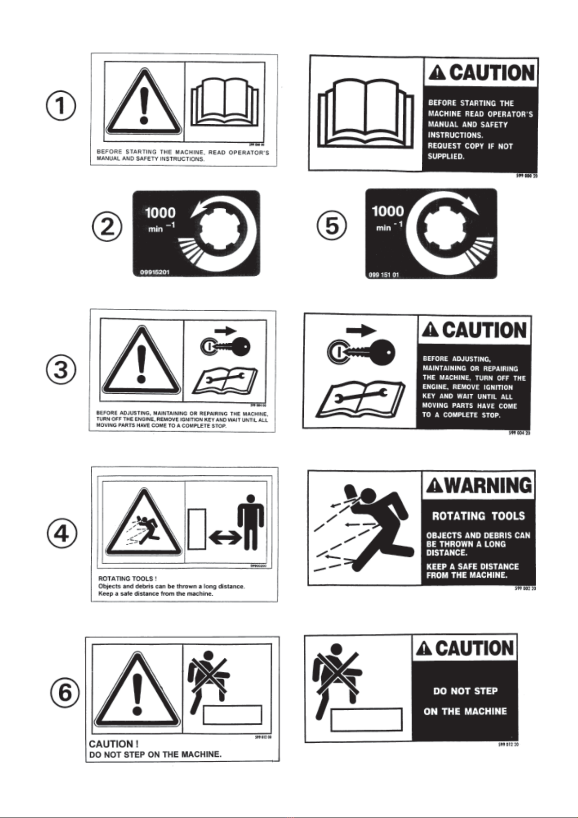
21. Before operati g the machi e, e sure that all safety guards are firmly i place a d i good co ditio . If wor
or damaged, replace immediately.
22. Before operati g the machi e, check tight ess of uts a d bolts, particularly o fixi g eleme ts (blades,
ti es, k ives, spades ...)
23. Keep clear of the machi e operati g area.
24. WARNING ! Da ger of crushi g a d sheari g ca exist whe compo e ts are operated by hydraulic or
p eumatic co trols.
25. Before leavi g the tractor or before adjusti g, mai tai i g or repairi g the machi e, tur off the e gi e,
remove ig itio key a d wait u til all movi g parts have come to a complete stop.
26. Do ot sta d betwee the tractor a d the machi e u less the ha d brake is tight a d/or stops have bee
placed u der the wheels.
27. Before a y adjustme ts, mai te a ce or repairs are carried out, e sure that the machi e ca ot be started
up accide tally.
ATTACHMENT
1. Whe attachi g or removi g the machi e from the tractor, positio hydraulic lift co trol lever i such a way that
it ca ot be set off accide tally.
2. Whe attachi g the machi e to tractor hydraulic li kage, e sure that diameter of li k pi s correspo ds to
diameter of ball joi ts.
3. WARNING ! Da ger of crushi g a d sheari g ca exist i the lifti g zo e of the tractor hydraulic li kage !
4. Do ot sta d betwee the tractor a d the machi e whe operati g the outer co trol lever of the lift mecha ism.
5. I tra sport, the machi e lift mecha ism should be stabilized by tractor tie rods to avoid floatatio a d side
shifti g.
6. Whe tra sporti g machi e e sure that it ca ot be lowered accide tally.

-5-
POWER TAKE-OFF
1. O ly use PTO shaft supplied with the machi e or recomme ded by the ma ufacturer.
2. PTO guards must always be i place a d i good co ditio .
3. Check for correct PTO overlap whe at work a d i tra sport.
4. Before attachi g or removi g the PTO shaft, dise gage PTO shaft, tur off e gi e a d remove ig itio key.
5. If a primary PTO shaft is equipped with a slip clutch or a free wheel, these must be fitted o the machi e PTO.
6. E sure that PTO shaft is always correctly fitted a d locked i to place.
7. Make sure guards are correctly i place a d secured with the safety chai s provided.
8. Before e gagi g PTO, e sure that PTO speed (rotational frequency) a d directio are i accorda ce with
ma ufacturer's recomme datio s.
9. Before e gagi g PTO, keep all people a d a imals clear from the machi e.
10. Never e gage PTO shaft whe tractor e gi e is tur ed off.
11. Never surpass PTO a gle recomme ded by the ma ufacturer.
12. WARNING ! Rotati g eleme ts ca co ti ue tur i g mome tarily after PTO is dise gaged. Keep clear u til
all rotati g eleme ts are at a sta dstill.
13. Whe removi g the machi e, locate PTO shaft o the supports provided.
14. Fit safety cap o tractor PTO.
15. Replace a y wor or damaged PTO guards immediately.
Rotatio speed ... rpm (America Measure) is also expressed i metric measure : Rotational frequency ... min -1.
Both u its are equivale t, for example : Rotatio speed 540 rpm equals Rotational frequency 540 min-1.

-6-
HYDRAULIC SYSTEM
1. WARNING ! Hydraulic system is u der pressure.
2. Whe fitti g hydraulic motors or cyli ders, e sure that co ectio s have bee made correctly, as per
ma ufacturers i structio s.
3. Before co ecti g hoses to the tractor hydraulics, e sure that tractor a d machi e circuits are ot u der
pressure.
4. It is stro gly recomme ded that the operator marks the hydraulic co ectio s betwee tractor a d machi e to
avoid maki g a wro g co ectio . WARNING ! Fu ctio s could be reversed (for example : lift/lower).
5. Check hydraulic hoses regularly ! Wor or damaged hoses must be replaced immediately.
Replaceme t parts must be i accorda ce with ma ufacturers recomme datio s co cer i g specificatio s
a d quality.
6. Should a leak be fou d, take all ecessary precautio s to avoid accide ts.
7. A y liquid u der pressure (particularly oil from hydraulics) ca pe etrate the ski a d cause severe i jury. If
i jured, see a doctor immediately, there could be da ger of i fectio .
8. Before a y adjustme ts, mai te a ce or repairs are carried out, lower the machi e, depressurize the circuit,
tur off the e gi e a d remove ig itio key.
MAINTENANCE
1. Before checki g a y machi e malfu ctio a d before adjusti g, mai tai i g or repairi g the machi e,
dise gage PTO, tur off e gi e a d remove ig itio key.
2. Check tight ess of uts a d bolts regularly. Retighte if ecessary.
3. If the machi e is raised, prop it up i a stable positio before carryi g out a y mai te a ce work.
4. Whe replaci g a worki g part, wear protectio gloves a d o ly use sta dardized tools.
5. It is forbidde to discard a y oil, grease or filters. These must be give to waste disposal orga isatio s to
protect the e viro me t.
6. Disco ect power source before a y work is do e o the electric system.
7. Check safety guards regularly, particularly those that are subject to wear. Replace immediately if damaged.
8. Spare parts used must be i accorda ce with specificatio s a d sta dards as defi ed by the ma ufacturer.
Use o ly ge ui e KUHN parts !
9. Before a y electric weldi g is carried out o tractor or attached machi e, disco ect ge erator a d battery
termi als.
10. Repairs o eleme ts u der pressure or te sio (spri gs, accumulators etc...) must o ly be carried out by
compete t perso s with sta dardized equipme t.

-7- SAFETY DECALS
SAFETY DECALS
THE FOLLOWING SAFETY PICTORIALS HAVE BEEN PLACED ON YOUR MACHINE IN THE AREAS
INDICATED. THEY ARE INTENDED FOR YOUR PERSONAL SAFETY AND FOR THE SAFETY OF
THE PEOPLE WORKING WITH YOU. THE TEXT SHOWN ON THEM GIVES THEIR PRECISE
MEANING. KEEP THE PICTORIALS LEGIBLE. IF THEY ARE NOT, REPLACE THEM.

-8-

-9-
SAFETY GUARDS
The safety guards protect against accidents and therefore ensure maximum machine
safety. EL 100 N for Great Britain are equipped with special guards (see page 23).
Fit the guard extension (1) over the
sheet metal guard (2) of the torque
limiter (see photo opposite).
Bolt both front guards (3) to the front support tube (13) ensuring that their ends
are kept as close as possible to outside of the machine.
Bolt deflectors (2, 10 and 11) respectively to front support tube (13), side gear
casing (14) and side plate (15) as shown on assembly diagram below.
1 = Thrust washer 13 x 24 x 3,2 9 = Hexagon bolt M12x50
4 = Self locking nut M 10 16 = Hexagon bolt M12x65 on housing side (14)
5 = U-bolt Hexagon bolt M12x55 on plate side (15)
6 = Spring washer M 12 17 = Hexagon bolt M12x30
7 = Hexagon nut M 12 18 = Spacer
8 = Hexagon bolt M12x35
Note : When fitting the machine with either a crumbler or a packer roller, first remove
the side guard (2). As position of the roller support arms conforms to safety
regulation, this side guard is no longer necessary and must be removed to avoid
interference.

-10-
The EL 100 N Power Tiller exists in three versions :
- EL 100 N with standard rotor equipped with curved blades.
- EL 100 N with cultiplow rotor which is ideal for preparing seed beds.
- EL 100 N with cultitiller rotor equipped with straight blades.
T E C H N I C A L S P E C I F I C A T I O N S
M O D E L S EL100N-230 EL100N-255 EL100N-305*
Working width (ins/cm) 90/230 100/255 120/305
Overall width with wheels (ins/cm) 100/254 110/279 130/330
Overall width with skids (ins/cm) 100/254 110/279 130/330
Number of blades fitted as std
in 3 pair formation 54 60 72
Number of flanges per std rotor 9 10 12
Number of flanges on cultiplow rotor 19 21 25
Number of blades on cultiplow rotor 76 84 100
Weight with standard rotor & wheels kg 715 756 850
lbs 1573 1663 1870
Weight with cultiplow rotor & wheels kg 780 830 930
lbs 1716 1826 2046
Weight with cultitiller rotor and kg 715 760 850
wheels ............................. lbs 1573 1672 1870
Minimum power requirement (hp/KW) 65 / 48 72 / 53 80 / 59
Number of speeds at 540 rpm
(min-1)
PTO 4 4 4
Number of speeds at 1000 rpm
(min-1)
PTO 4 4 4
Working depth adjustable to : 9" / 22 cm
OPTIONAL
- Crumbler roller : weight without
removable bars (lbs/kg) 388/155 364/165 408/185
- Packer roller : weight 801/320 772/350 860/390
- Rear 3-point linkage : weight 154/ 70
PTO transmission shaft with safety clutch
Linkage : Cat II & III adjustable lower links
Optional (to replace wheels) set of skids
* WHEN TRANSPORTING THE MACHINE ON THE PUBLIC HIGHWAY, IT IS THE RESPONSIBILITY OF
THE OPERATOR TO ENSURE THAT THE MACHINE COMPLIES WITH THE HIGHWAY CODE.

-11-
FITTING TO THE TRACTOR
The EL 100N Power Tiller can be fitted to all tractors with a standard 3-point frame
and Cat. I or II lower link pins.
For tractors with Cat. II linkage, the lower link arms are fitted to the interior
of the attachment bracket (fig. A). For tractors with Cat. III linkage, the lower
link arms are fitted to the interior or exterior of the attachment bracket (fig. B
and C).
Cat. II Diameter 25 - 28mm Figure A L = 870 mm
(1" - 1 1/10") (34 1/4")
Cat. III Diameter 31 - 37mm Figures B and C M and N = 1010mm
(1 - 1 5/11") (39 3/4")
PTO DRIVE SHAFT
Before attaching the PTO shaft to the slip clutch flange, it is essential that both
mating surfaces are thoroughly cleaned.
Bring both components together and fix in place using the self-locking screws
provided. Tighten all the studs to a torque setting of 10 daNm at the same time making
sure that the flange is centrally seated.
AFTER THE FIRST FEW MINUTES OF OPERATION, THE FLANGE STUDS MUST BE CHECKED FOR
TIGHTNESS AND THEREAFTER CHECKED DAILY, TIGHTENING THEM WHEN NECESSARY.

-12-
After mounting the power tiller, stabilize the tractor 3-point linkage with whatever
means are recommended i.e. the bars, chains etc. Couple the PTO shaft to the tractor
(with the gear lever in neutral position).
Adjust the top link (I) length to a position where the tiller input shaft (J) is
parallel to the ground.
In this position :
- The 2 angles (K) between PTO yoke centre line and axes of the PTO sliding tubes
must be equal and not exceed 30°.
- Overlap of sliding tubes (L) must be at least 22 cm (9").
Disengage the tractor PTO shaft and lift the machine using the hydraulics.
In the raised position :
- The 2 PTO sliding tubes must not completely overlap each other ; a safety gap (M)
of 1 cm (3/8") should exist between end of sliding tube and yoke.
- Yoke angles (K) must not exceed 40°.
If above situation does not exist, proceed as follows :
- Shorten both tubes by an equal length.
- Decrease lifting height of the tractor lower link arms but ensure that there is
sufficient ground clearance under the rotor.
Repeat this adjustment each time the machine is mounted to a different tractor.
The working depth (2 to 20 cm - 3/4" to 7 7/8") should be controlled by either the
two wheels or with the two skids or with the roller which is available as optional
extra.
To avoid accidents which could be
serious, make sure that the guards are
always correctly in place and secured
with the safety chains. The safety chain
on the machine side must be attached to
the gearbox guard. All worn or damaged
guards must be replaced immediately.
A safety chain (C) is supplied with the
machine to support the PTO shaft (T) when
disconnected to avoid damage or
deterioration due to contact with the
ground.
Fit the chain (C) to hook (U) as shown
in figure opposite.

-13-
SLIP CLUTCH SETTING
The spring pressures are adjusted before delivery (L = 34 mm) to give a correct load
with a PTO speed
(rotational frequency)
of 1000 rpm
(min-1)
. The theoretical length
(L) of the springs (R) is :
- 540 rpm
(min-1)
:
EL 100N/230 : 33.5 mm (1 5/16")
EL 100N/255 : 32.8 mm (1 9/32")
EL 100N/305 : 32 mm (1 1/4")
- 1000 rpm
(min-1)
:
EL 100N/230 : 35.8 mm (1 13/32")
EL 100N/255 : 35.4 mm (1 25/64")
EL 100N/305 : 34.8 mm (1 3/8")
These figures are average settings and slight deviations can be made according to
working conditions and tractor engine rating. The springs of the slip clutch must
all be equally adjusted to a setting where the implement can operate under normal
conditions without the plates sliping. However, when extreme ground conditions are
encountered as well as obstructions, the friction plates must slip.
IMPORTANT : * When starting operation, check immediately that the slip clutch is
correctly set for the prevalent ground conditions.
* Check that working temperature remains between 30° and 40° (86° and
104°F).
Setting too light = over heating and rapid wear of the friction plates.
Setting too heavy = risk of damage to machine elements.
The setting of the safety clutch should be checked regularly. To do this, slacken
the six springs (R) and allow the friction plates to revolve for a few moments, then
retighten to the correct settings given above.
NEVER COMPLETELY COMPRESS THE SPRINGS.
Note : For easier access when wishing to adjust the slip clutch, we strongly recommend
that you firstly remove the clutch guard. Do not forget to replace the guard
after adjustment is made.
ROTOR SPEED
(ROTATIONAL FREQUENCY)
The EL 100 N Power Tiller can be operated with a tractor PTO speed
(rotational
frequency)
of 540 or 1000 rpm
(min-1)
. With the gear lever, eight different rotor speeds
and a neutral position can be selected (see table page 14).
The change gear ratios, the machine must first be tilted forward to prevent any oil
loss when the rear cover is opened.

-14-
21 24 19 26
POSITION OF
GEARS
1st 2nd 1st 2nd 1st 2nd 1st 2nd
24 21 26 19
Standard gear set
* Recommended speeds
(rotational frequencies)
Works setting
PTO
SPEED
(ROTATIONAL
FREQUENCY)
1000 rpm
(min-1)
224 270 292 352 187* 225* 350 422
540 rpm
(min-1)
- - - 190 - - 189* 228*
Optional (21/24 teeth)
(Set No. 120 7710)
The gearbox is fitted with a rear PTO
shaft which turns at the same speed
(rotational frequency)
as the tractor
drive shaft. This rear drive shaft
should not be used to drive a secondary
machine while the gearbox is in its
neutral position (due to the risk of
gearbox damage resulting from inefficient
oil circulation).
The rear PTO shaft (1 3/8" 6 spline
profil) should not be used to transmit
more than 37 kW (50 hp).
If the rear PTO shaft is not used, always put cover (E) in place.
FITTING THE BLADES
1. STANDARD ROTOR
According to the type of work being carried out, the blades can be fitted in 2 ways:
- 3 pair formation (3 right D and 3 left G) as fitted at the factory.
- 2 pair formation (2 right D and 2 left G).
To recognise the difference between left-hand side and right-hand side blades, notice
that the cutting edge follows the direction (f) of rotation.
F = Forward direction
To fit blades helicordally, proceed as
follows :
- Always start the fitting on each flange
with the same type of blade and the same
place (opposite mark R page 12 which is
either a hollow or a chamfer).
- All blades are fitted on the left-hand
side of the flanges viewed from the rear.

-15-
2. CULTIPLOW ROTOR
On EL 100N equipped with
cultiplow rotor, blades (L)
must be fitted alternatively
to the left and right-hand
side of the flanges.
- All bolts go on the blade side and the nuts and lock washers on the flange side.
3. CULTITILLER ROTOR
The cultitiller rotor is equipped with
angled blades bolted onto supports
individually welded on the rotor central
tubing. When fitting blades, start on
the left hand side support (i.e. gearbox
side) by facing the blade cutting edge
towards the left-hand side of the
machine (viewed in the forward direction
F).
Next fit the diametrically opposite
blade by facing the cutting edge towards
the right-hand side of the machine. Keep
fitting left-hand and right-hand blades
alternatively, moving towards the right-
hand side support, ensuring that all
cutting edges always follow the direc-
tion of rotation (f).
CAREFULLY TIGHTEN UP ALL BOLTS : - 16 daNm (118 ft/lbs) for the standard rotor with
angled blades
- 22 daNm (162 ft/lbs) for the cultiplow rotor and
for the cultitiller rotor.
When the blades or spades are worn, change the complete set to avoid throwing the
rotor out of balance.
Diagram : clod sizes
This diagram shows theoretically achieved clod sizes with variable parameters such
as number of pair of blades fitted, forward speed and selected rotor speed
(rotational
frequency)
.

-16-

-17-
LUBRICATION
*PTO transmission shaft (item 8) : Grease the telescopic tubes and universal knuckle
joints daily (2 grease nipples) with Shell Multi-purpose grease NLGI grade 2.
*Depth wheels (item 12) : Greased for life with Shell Multi-purpose grease NLGI grade
2.
*Rotor : Periodically grease (approx. every 20 hours) with Multi-purpose grease NLGI
grade 2, the grease nipple (item 14) situated at the non-drive end of the rotor.
OPERATION
The tilth depends on the type of work to be carried out. The degree of tilth is governed
by combining the following factors :
- 2 or 3 pair formation
- Position of rear shield
- Rotor speed
(rotational frequency)
- Forward speed
- Working depth FINE TILTH COARSE TILTH
- Rotor speed
(rotational frequency)
2nd 1st
- Rear shield Down Up
- Forward speed Slow Fast
- Blade formation 3 pairs 2 pairs
Proposed combinations Rotor speed Rear shield Tractor Blade
rpm
(min-1)
position speed formation
Work required 2nd 1st 1,6 to 3 3 to 6 3 2
238 182 Down Up km/hr km/hr pairs
(1 to 2 (2 to 4
mph) mph)
Seedbed preparation spring * * * *
Seedbed preparation autumn * * * * *
Turning in green crop * * * *
Turning in crop residues * * * *
Turning manure * * * *
Reclamation of grassland * * * * *
Vineyard cultivation * * * *
Orchard cultivation * * * *
Weeding * * * *
Land clearance * * * * *
Brushwood clearance * * * * *
Turning in stubble * * * * *
Market gardening * * * * *
Forest maintenance * * * *
The EL 100 N fitted with cultiplow rotor or with cultitiller rotor is designed for
following types of work :
- Soil cultivation in ploughed land.
- Market gardening.
- Reclamation of grassland.
- Turning in stubble.
- Surface and indepth soil loosening.

-18-
* Roller greasing : Periodically grease (every 20 hours) the housings (2 grease
nipples) at each end of the roller (item 2) with Shell Retinax EP.
Regularly lubricate the turn buckle threads (item 13).
*Central and side gearboxes : Change oil after the first 20 hours of operation and
thereafter every 100 hours.
Central gearbox Side gearbox
Filler plug Item 11 Item 7
Drain plug Item 9 Item 3
Fill just to level plug Item 10 Item 5
Quantity oil SHELL SPIRAX SAE 90 EP 4,5 l (8 Imp. pts) 1,75 l(2.9 Imp.pts)
Check the oil levels weekly.
Lubricate all other exposed pivot joints and hinges with Shell X 100 oil or SAE 90
EP oil.
FOR TROUBLE FREE OPERATION OF YOUR
MACHINE WE RECOMMEND THE USE OF SHELL
PRODUCTS.
EQUIPMENTS
I. ROLLER
The EL 100 N can be equipped with 2 types of rollers :
- Crumbler roller made up of fixed tubes and removable bars.
- Packer roller, made up of a cylinder fitted with several rows of studs.
Table of contents
Other KUHN Tiller manuals