BRIGHT BLUE COLIBRI User manual

“COLIBRI / PLUMA CC”
SALT CHLORINATOR


Index
1Safety Instructions.................................................................................................................................................3
1.1 Warnings ..........................................................................................................................................................3
2EC Conformity.........................................................................................................................................................3
3System Contents....................................................................................................................................................4
4Installation................................................................................................................................................................4
4.1 Hydraulic Installation...................................................................................................................................4
4.1.1 Electrolysis Cell........................................................................................................................................4
4.1.2 Temperature probe installation........................................................................................................5
4.2 Electrical Installation....................................................................................................................................5
4.2.1 Installation of Electrolysis Cell...........................................................................................................5
4.2.2 Installation of Temperature Probe ..................................................................................................5
4.2.3 External Controller Installation (Optional)....................................................................................5
4.2.4 Automatic Coverage Detector Installation (optional)..............................................................6
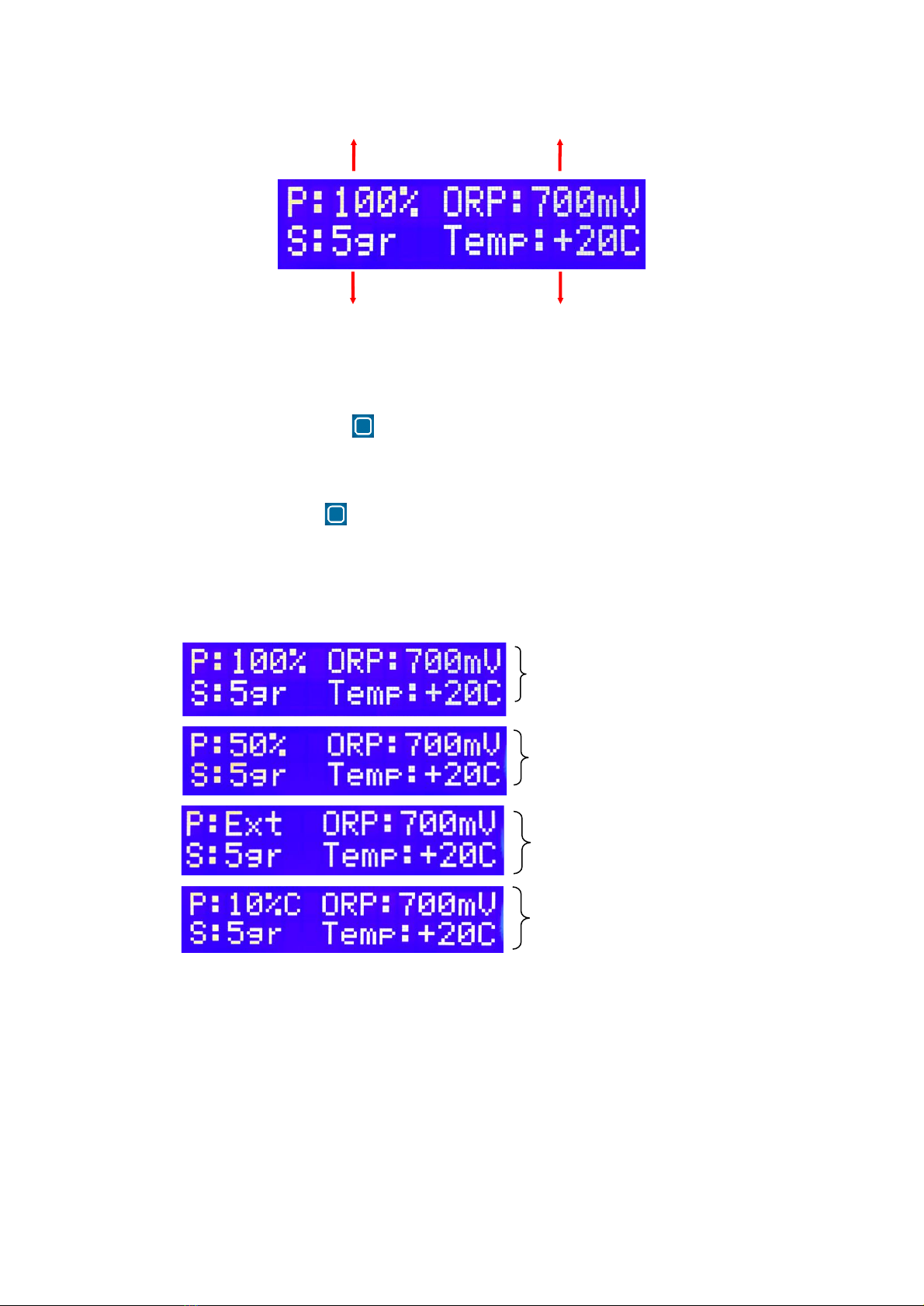
5Operation .................................................................................................................................................................6
5.1 Control of Chlorine Production...............................................................................................................7
5.2 Operation with Temperature Probe ......................................................................................................7
5.3 Operation with Chlorine Probe (ORP) ..................................................................................................8
5.4 Operation with External Probe ................................................................................................................8
5.5 Operation with Pool Coverage................................................................................................................8
5.6 Low Salt Indication.......................................................................................................................................8
5.7 Disinfection Recommendations..............................................................................................................9
6Configuration and Calibration..........................................................................................................................9
6.1 ORP Calibration .......................................................................................................................................... 10
6.2 Setting ORP Limits..................................................................................................................................... 10
6.3 Polarity Inversion Setting........................................................................................................................ 11
6.4 Swimming pool volume configuration.............................................................................................. 12
6.5 Cell type setup ............................................................................................................................................ 12
7Alarms..................................................................................................................................................................... 12
7.1 Alarm 1 - Low Flow ................................................................................................................................... 12
7.2 Alarm 2A - High Salt................................................................................................................................. 12
7.3 Alarm 4 –Relay........................................................................................................................................... 13
7.4 Alarm 5 –Source........................................................................................................................................ 13
8Electrolysis Hour Totalizer............................................................................................................................... 13
9Terms and Conditions ...................................................................................................................................... 14
9.1 Copyright ...................................................................................................................................................... 14
9.2 Warranty........................................................................................................................................................ 14
9.3 Warranty Exclusions.................................................................................................................................. 14
IMPORTANT WARNING
Do not use chloridric / muriatic acid to lower the pH. The
ventilation system sucks air into the equipment, so it is
important to keep the pH solution tank as far away from the
equipment as possible, to prevent corrosion inside the machine.

©Copyright EN-V2020
The information in this document is subject to change without notice 3
1Safety Instructions
This product is a combination of an electronic controller and the respective accessories. It
has been assembled and tested according to the safety measures applied to electronic devices in
the EC. It has been cleared by the quality department within the factory. To preserve status and
guarantee operation safety, the following instructions must be observed.
Only licensed personnel must execute product installation.
Electrical installation must be done according to local electrical safety regulations.
Product connection to the power line must allow for total isolation (phase, neutral and
earth) to ensure safe repair and maintenance operations. A differential switch with a maximal earth
fault current of 30mA should shield all circuitry.
Before turning on the controller it is recommended to verify its physical conditions as well
as the circuitries. In case of installation in a warmer place than origin leave the controller’s door
open to stabilize temperature and avoid condensation of the electronic components.
When the controller is turned on remember to let the capacitors discharge before handling
them to avoid electric shock.
1.1 Warnings
Risk of Electrocution
The controller’s components carrying electrical tension, which might lead to
electrocution, are signalled with the following symbol:
The performance of any electrical operation by unauthorized personnel is entirely
forbidden. The equipment must be turned off before any maintenance operation.
Risk of human failure
Product operation should follow adequate training to all personnel handling the
equipment. Special attention must be paid to electrical and chemical safety
measures before using the equipment.
2EC Conformity
The manufacturer declares that the electronic equipment for pool water treatment of its
production are in compliance with the technical requirements:
•EN 50274:2002
•IEC 60335-1:2006
•IEC 60947-1:2007
•IEC 62026-1:2007
and the EC directives:
•Low Voltage Equipment Directive 2006/95/CE
•Electromagnetic Compatibility Directive 2004/108/CE.

©Copyright EN-V2020
The information in this document is subject to change without notice 4
3System Contents
This equipment is supplied in a box containing the electronic controller, the electrolysis cell, 2
reductions 63/50mm, 1 cover for the cell cables, 1 fixing bracket and its screws, a clamp saddle
and a temperature probe.
Before any installation, make sure that all components are in the original box.
4Installation
This controller includes a front display, a main control button and two side switches.
The controller must be set up vertically, on a plane surface, keeping at least 15cm from the wall
and from other components to ensure proper ventilation.
Before beginning installation of the electrolyses cell make sure that hydraulic circuits are shut and
before beginning installation the equipment make sure that the power supply is isolated.
4.1 Hydraulic Installation
Fig 1- Hydraulic System Scheme
4.1.1 Electrolysis Cell
The electrolysis cell can be installed horizontally or vertically. In the vertical installation
the electrical wires must be faced upwards, to allow for the build-up of gases originated from the
electrolysis process on the top of the cell if there is a water circulation failure (Fig.3).
Fig 2 - Electrolysis Cell Fig 3- Electrolysis Cell Position

©Copyright EN-V2020
The information in this document is subject to change without notice 5
The cell entry must be connected after the sand filter as shown in Fig 1. When possible, it is
recommended to screw the cell tubing to a wall or a strong panel to prevent it from disruption
due to the mechanical effort caused by the cell’s body.
4.1.2 Temperature probe installation
The installation of the temperature probe should be performed with a clamp saddle with
½" output, always between the sand filter and the electrolysis cell.
Fig 4 –Clamp Saddle
4.2 Electrical Installation
4.2.1 Installation of Electrolysis Cell
The connection to the electrolysis cell is done through two conductors of 2.5 to 6mm2
(depending on the cell power) and two conductors of 0.75mm2, both supplied with the system.
One of the 0.75mm2 conductors has one tined terminal, the remaining conductors have M6
terminals which must be connected to the corresponding terminals in the cell (see Figure 5).
Fig 5 –Electrolysis Cell Connection Terminals
4.2.2 Installation of Temperature Probe
The temperature probe comes from factory connected to the equipment as shown in
figure 6.
4.2.3 External Controller Installation (Optional)
If you choose to connect an external controller, it must emit a potential-free signal which
must be transmitted to the equipment via specific cable (consult the manufacturer). That cable i
connected inside the equipment (view Fig. 6), removing the cables cover, with help of a phillips
screwdriver, existent on the lower left part of the equipment
Gas detector
Electrolysis
Cell Power

©Copyright EN-V2020
The information in this document is subject to change without notice 6
4.2.4 Automatic Coverage Detector Installation (optional)
If the pool has an automatic cover system, it can be connected to the equipment, so it detects
if the cover is open or closed. The automatic Cover must emit a potential-free signal that must be
transmitted to the equipment via specific cable (consult the manufacturer), which is connected to
the inside the equipment (view Fig. 6), removing the cables cover, with help of a phillips
screwdriver, existent on the lower left part of the equipment
Figure 6 –Internal Connections
5Operation
Figure 7 –Command Buttons
This device only has tree buttons: Main Control Button , the Side Cover Switch and the
Side Power Switch (see figure 7).
IMPORTANT NOTICE: The equipment should only be connected in conjunction with the
circulation pump or when the circulation pump is already switched on.
ORP Probe
Temperature Probe
Contacts 1 and 2
Automatic Coverage
Detector
Contacts 5 and 6
Gas Detector
Contacts 7 and 8
External Chlorine Controller
Contacts 3 and 4
Plug-In ORP
Pool Cover:
Coverage Closed (button on top)
Open Cover (button on bottom)
Main Control Button
Power Switch:
0 –OFF
I –ON

©Copyright EN-V2020
The information in this document is subject to change without notice 7
The display allows you to view the system status and obtain information about the active alarms.
Figure 8 –Display Information
5.1 Control of Chlorine Production
Pressing the control button selects the period of electrolysis (as a percentage of filtering
time) in order to increase or decrease production, and always choose the best reality of the
swimming pool in which the equipment is installed.
Pressing the control button the percentage ("P: __%") is changed and can be set to between
0% and 100% in intervals of 5%. or "EXT" mode, when the equipment is to be controlled by an
external control unit.
You should use the cover mode when the pool is closed, and choose the % required between 0%
and 50%, with intervals of 5% (see chapter 5.4).
Figure 9 –Menus Indicating Chlorine Production
5.2 Operation with Temperature Probe
The variation of the water temperature has a direct influence on the need to increase or
decrease the electrolysis production time. When the temperature probe is installed, the
production cycles are automatically increased when the temperature rises, or decreases when it
goes down, in order to ensure a more accurate and more effective treatment.
When the water temperature is below 12 ° C, the production has to be turned off to not affect the
operation and durability of the electrolysis cell. When a temperature bellow 12ºC is detected the
Chlorine Production
Chlorine Concentration
Salt Concentration
Water Temperature
Production at 100%
Salt Concentration: 5gr/l
Production at 50%
Salt Concentration: 5gr/l
Production with closed coverage
Salt Concentration: 5gr/l
Production with external probe
Salt Concentration: 5gr/l

©Copyright EN-V2020
The information in this document is subject to change without notice 8
temperature indication and STBY starts to flash on the equipment screen. The manufacturer shall
not be liable for any equipment or cell that proves that this protection procedure has been
breached.
5.3 Operation with Chlorine Probe (ORP)
The ORP probe allows you to measure the concentration of chlorine in the pool in order
to avoid excesses or deficiencies of disinfectant in the water. When the ORP module (optional)
and ORP probe (optional) are connected, the real time chlorine readout (ORP: _____ mV) is
displayed on the machine's display.
In this mode, chlorine production should be set to (P100%) and ORP limits for the range that
best fits the pool reality where the equipment is installed (see Chapter 6 for setting ORP limits).
When the real time chlorine value is greater than the memorized maximum setpoint, the ORP
indication (ORP:____mV) and the STBY indication starts to flash, informing the user that
equipment is in standby because the chlorine production as reached the desired setpoint.
5.4 Operation with External Probe
The equipment has a potential-free input for the connection of an external controller (see
section 4.2.3) which will act on the system by switching the electrolysis on or off depending on
the concentrations that are programmed in the system. In this case, the device must be set to
"EXT" mode.
It is recommended that electrolysis is not frequently activated and deactivated because it reduces
cell life. Bright Blue is not responsible for errors or faults of the external equipment that have a
direct effect on the quality and disinfection of the pool water.
5.5 Operation with Pool Coverage
The production of chlorine when the pool is covered must be lower than that of the
uncovered pool. When the cover mode is activated, production is automatically reduced (see
chapter 5.1).
In electrical coverings the process can be automatic if the cover is connected to the equipment
(see chapter 4.2.4).
In case the cover is manual, the user must set in the equipment the cover side switch to the closed
position whenever the pool is covered.
5.6 Low Salt Indication
This indication shows that the salt concentration is below the minimum recommended.
The system will keep running but the electrolyses production is reduced and cannot be enough
for a good water disinfection. On screen (figure 10) shows the quantity of Salt (in kgs) that should
be added to the swimming pool for the concentration to reach the recommended value of 5gr/l.
Before adding Salt to the swimming pool, should be checked:
•The salt in the water is completely diluted
•All valves are correctly positioned
•Cell is in good condition and inside its lifespan
•If cell electrodes have a “whitish” colour, i.e., if have mineral deposits*
•The equipment is correctly regulated

©Copyright EN-V2020
The information in this document is subject to change without notice 9
(*) - In this case a cell cleaning may be needed. To clean it, insert the electrodes into a 10%
hydrochloric acid solution until it stops reacting, typically no more than 10 minutes. This operation
reduces the life expectancy of the electrolyses cell, it should only be performed if it has visible
mineral accumulation.
Once the problem has been corrected this indication will automatically disappear and the
swimming pool salt concentration will be showed.
Figure 10 –Indication of quantity of salt to add
5.7 Disinfection Recommendations
It is advisable to disinfect it overnight. In fact, ultraviolet radiation acts on the chlorine
produced by the electrolysis cell, catalysing salt regeneration (which is why salt consumption is
insignificant). If disinfection is carried out overnight, the chlorine concentration rises rapidly, and
the disinfecting effect is much more effective.
For good disinfection practice it is also advisable to maintain a concentration of chlorine stabilizer
(isocyanuric acid) of 35 ppm, i.e., 35 g/m3of water. This concentration, although reduced, allows
to diminish the diurnal losses of chlorine by the effect of ultraviolet radiation.
6Configuration and Calibration
All equipment’s are supplied properly configured and calibrated at the factory so that it is
not necessary to use these operations at the time of installation.
If you wish to change the factory settings or need to calibrate the ORP probe, change ORP limits
or change the polarity inversion time, proceed as described in the following chapters.
To enter the Setup/Calibration menu, move the cover side switch to pool covered and press the
Command Button for 5 seconds until the display shows:
Figure 11 –Calibration/Configuration Menu
Select what you want to configure/calibrate by briefly pressing the Command Button until
the desired option appears on the bottom line: CAL. ORP. - for ORP calibration; LIM. ORP –for
setting the ORP limits; INV.POL - for setting the polarity reversal time; VOL –for setting the
pool volume; CEL –for setting the electrolyses cell type installed on the equipment; BACK –
back to the main screen.
Once the desired option has been selected press the Command for 5 seconds to enter the

©Copyright EN-V2020
The information in this document is subject to change without notice 10
6.1 ORP Calibration
The calibration of the ORP probe is done with 2 buffers (240mV and 470mV). Before
proceeding, confirm that you have all the necessary material including a glass of water and
absorbent paper in order to clean the probe before introducing the buffers.
To enter the ORP calibration, select the CAL.ORP option in the Calibration / Configuration menu
(see chapter 6).
When entering calibration, the following information will appear on the screen:
Figure 12 - Inserting the ORP probe into the standard 240mV
Insert the probe into the 240mV buffer, wait 10 seconds, and briefly press the Command
Button . The first line of the display indicates the default value, and the second line shows
the actual reading and a dashed line indicating that the system is calibrating (Fig. 13).
Figure 13 - Standard ORP Calibration 240mV
When the calibration is completed at 240mV, "OK" appears on the display and the buffer
470mV is requested. Repeat the entire process with the 470mV buffer until the calibration is
complete.
6.2 Setting ORP Limits
This menu allows you to configure the ORP (HIGH) and minimum (LOW) limits to
determine the correct concentration of chlorine in the water. The value of ORP is not the same
from pool to pool being dependent on factors external to the equipment, so the correct limits
should be checked case by case in the pool where the equipment is installed.
To set the ORP limits, choose LIM.ORP in the Calibration / Configuration menu (see Chapter 6).
When you enter the menu, the following screen appears:
Figure 14 - Change in ORP Limits
To set the limits, briefly press the Command Button and appears:
Figure 15 - Definition of Upper Limits

©Copyright EN-V2020
The information in this document is subject to change without notice 11
To change the saved ORP limit, first, check if the digit you want to change is flashing. When the
digit to change is flashing, briefly press the Main Command Button and the digit will be
increased till 9 and going back to 0 for every brief press on the Main Control Button
To move to the next digit, do not press any buttons and wait for 5 seconds, next digit will start
flashing. Repeat these steps until the correct value is written on the screen.
To save the new ORP limit press the Main Command Button for 5 seconds.
To save the desired value, press the Command Button for 5 seconds and move to the lower
limit setting.
Figure 16 - Definition of Lower Limits
Repeat the previous steps and record. After the operation is completed, the following screen
appears:
Figure 17 - New Limits of ORP
6.3 Polarity Inversion Setting
The polarity inversion process is responsible for the self-cleaning of the electrolysis cell in
order to ensure that it does not accumulate limestone, consequently losing its production
capacity.
The correct time interval between each inversion of polarity depends on the chemical
characteristics of the water, namely its calcium hardness. The higher the water hardness, the lower
the defined range should be, to ensure that no encrustation occurs on the titanium plates.
The equipment is factory set at 6H and can be changed to a range between 3H and 8H.
IMPORTANT: the shorter the inversion time the shorter the lifetime of the electrolysis cell.
To change the polarity inversion, select the INV option in the Calibration / Configuration menu
(see chapter 6).
When you enter the menu, the following screen appears:
Figure 18 - Polarity Inversion Time

©Copyright EN-V2020
The information in this document is subject to change without notice 12
To change the value, briefly press the Command Button to set the desired time. To record
press the Command Button for 5 seconds.
The "Test Inv" option is used to run a diagnostic test to verify that both polarities work. When
you choose this option, the system will start one of the polarities for a few seconds, then stop to
reverse and starts again on the other polarity.
6.4 Swimming pool volume configuration
This menu allows to save the swimming pool volume (in m3). This volume is used to calculate the
quantity of salt to add into the swimming pool, in case of a low salt concentration is detected.
To change the saved volume value, first, check if the digit you want to change is flashing. When
the digit to change is flashing, briefly press the Main Command Button and the digit will be
increased till 9 and going back to 0 for every brief press on the Main Control Button
To move to the next digit, do not press any buttons and wait for 5 seconds, next digit will start
flashing. Repeat these steps until the correct value is written on the screen.
To save the new volume value press the Main Command Button for 5 seconds.
Figure 19 - Define pool volume
If you do not wish to save the new swimming pool Volume, restart the equipment, using the side
power switch. The equipment will keep the last saved swimming pool Volume value.
6.5 Cell type setup
IMPORTANT NOTICE: This function should only be carried out by trained and qualified personnel.
This function allows the configuration of the cell connected to the equipment.
7Alarms
7.1 Alarm 1 - Low Flow
This alarm (ALARM 1) is released if there is not sufficient water flow in the electrolysis cell.
When the alarm is triggered, the system goes into standby to safeguard the integrity of the
equipment. It should be verified that:
•All valves are correctly positioned
•There are no hydraulic leaks
•The filter is in the filtering position
Once the problem has been corrected the alarm will be automatically deactivated.
7.2 Alarm 2A - High Salt
This alarm (ALARM 2A) indicates that the salt concentration on the swimming pool is to high
(* to use sea water, please contact manufacturer).
It should be verified that:
•The salt concentration in the water is below 9g/l
•The salt in the water is completely diluted

©Copyright EN-V2020
The information in this document is subject to change without notice 13
•The equipment is correctly regulated
Once the problem has been corrected, you must restart the machine to disable the alarm.
7.3 Alarm 4 – Relay
This alarm (ALARM 4) turns on when the mainboard fails.
Contact technical service.
7.4 Alarm 5 – Source
This alarm (ALARM 5) turns on when the power supply fails.
Contact technical service.
8Electrolysis Hour Totalizer
This equipment has an electrolysis hour counter to monitor the use and the life of the
electrolysis cell. The device counts the time when it is actually in production, not considering the
when it is connected, but in standby mode. To view the total number of hours already used, with
the side cover switch to Open press the control key for 5 sec. until the information appears
on the screen.

©Copyright EN-V2020
The information in this document is subject to change without notice 14
9Terms and Conditions
9.1 Copyright
This User Manual contains information secured by copyright. All rights are reserved to
Bright Blue, Lda.
This User Manual has been written for personal use. The copy, reproduction or translation of the
present document, as a whole or partially, requires prior written consent from Bright Blue, Lda.
9.2 Warranty
This product, composed by the electronic controller and accessories, was constructed and
tested in accordance with the security measures applicable to electronic devices and has
undergone the most rigorous quality controls, leaving the factory in perfect condition.
This warranty applies to products manufactured by Bright Blue Ltd, in accordance with the
terms and conditions of the company.
The Bright Blue Ltd guarantees the product manufactured in accordance with the
conditions and responsibilities of these terms for a period of:
•COLIBRI: 4 years or 12.500h of operation for the electrolysis cell; 5 years for the electronic
equipment; Twelve months for temperature probes, except ware out.
•PLUMA: 2 years or 10.500h of operation for the electrolysis cell; 2 years for the electronic
equipment; Twelve months for temperature probes, except ware out.
The Bright Blue Ltd reserves the right to change the terms and conditions of this warranty,
without notice, even after the invoice date of purchase, applying the terms and conditions in force.
9.3 Warranty Exclusions
Warranty and Responsibility does not apply to:
•accessories, consumables and peripherals that are not included in the original product
package and/or that have been purchased to other companies;
•original identification marks that have been torn, changed or removed from the
equipment or product;
•S/N that have been torn, changed or removed from the equipment and/or from its
components;
•flaws and defects due to accidents, negligence or improper use of the equipment and its
components; flaws and defects from improper electrical installation; unusual physical or
electrical stress; disrespect for environmental rules, abnormal conditions of temperature,
moisture, corrosive matters or other climate conditions that spread beyond the
predefined limits;
•operation beyond capacity, failure to report to Bright Blue within the warranty period,
substitution of parts not approved by Bright Blue, failure or damage due to
misapplication, lack of proper maintenance, abuse or improper installation;
•use and operation of the equipment, or product, in contradiction to the system’s
documentation written by Bright Blue;
•system failure that according to Bright Blue is not due to raw material defect or fabrication
deficiency;
•system failure caused by inadequate supervision of the components that are subject to
wear down or breakdown;
•product alteration and/or repair by unauthorized personnel and/or unapproved by Bright
Blue;
•customers that did not follow the procedures described in this specified warranty;

©Copyright EN-V2020
The information in this document is subject to change without notice 15
This warranty substitutes all others, explicit or implicit, including, but not limiting itself to
implicit commercial warranties and adequacy to a predetermined objective of the equipment and
corresponding documentation.
Bright Blue’s responsibility is limited to repair and/or substitution of product components as
long as none of the warranty exclusion conditions is met.
Under any circumstance is Bright Blue responsible for any cost, tax, expense, loss or damage
of any kind, directly or indirectly, consequential or accidental, including, but not limited to ceasing
profits.
The present limited responsibility represents the overall responsibility assumed by Bright Blue
concerning its products, articles, goods, and provided services. Bright Blue will not have an further
obligation or responsibility, moral or otherwise. Nevertheless, its responsibility limitation does not
affect or limit the customer’s legal rights in any way in regard to the sale of consumer goods and
investment in its country.
Bright Blue does not take responsibility for any delay or fault caused by circumstances outside
its control. Possible situation include, but are not limited to, interrupted communications services,
carrier delays, errors or interruptions that impede the delivery of goods, unexpected situations,
climatic conditions, strikes, inability to establish contact the customer or any responsible entity to
report and/or confirm the situation.
Any technical assistance necessary will be provided within Bright Blue’s factory and never on
site of installation. The freight cost from the site to the factory will is the responsibility of the client.
If Bright Blue, or its representative, determines that the equipment repair is covered by the
warranty period and conditions, the costs of analysis, repair and transportation back to the site
will be the responsibility of Bright Blue, or its representative.
If Bright Blue, or its representative, determines that the repair is not covered by the warranty
clauses, for the reasons explained above, it will not be concluded until integral payment of the
invoice issued. In this case, Bright Blue or its representative will send the customer an estimate of
the diagnosis, repair and transportation costs. The customer can order the return of the goods,
without repair, in which case Bright Blue will issue an invoice of the diagnosis fee and dispatch
costs. If the customer requires the repair, Bright Blue will charge the repair and transportation
costs. The goods will be returned after full payment.
This manual suits for next models
1
Table of contents
Popular Water Filtration System manuals by other brands

WilTec
WilTec NW-RO50-C1 Operation manual

Pentair
Pentair CLEARPRO TECHNOLOGY TR100 Installation and user guide

Shure
Shure UAPF-X1 quick start guide

Culligan
Culligan 9" Installation, operation and service instructions

Environmental Water Systems
Environmental Water Systems EWS-1354-1.5 quick start guide

A.O. Smith
A.O. Smith AO-US-200 owner's manual