INSTALLATION GUIDE
Actual product characteristics may vary. Bright Light reserves the right to improve, modify or update the product designs without prior notice.
ENCAPSULATED LED RIBBON | LITE
COLOUR CODE LUMENS
WARM WHITE
3000K BL-LS-4300-30 ≥180lm/m
NATURAL WHITE
4000K BL-LS-4300-40 ≥250lm/m
BLUE
455–460nm BL-LS-4300-B ≥35lm/m
LED WATTS 7.2W/m
INPUT VOLTS 24V DC constant voltage
OPERATING TEMP. -25°C ~ +60°C
MAX. RUN PER
POWER FEED
15m using one feed
30m using two feeds
DIMENSIONS W6 × H12mm
(W8mm for connectors)
CUTTING LENGTH 50mm
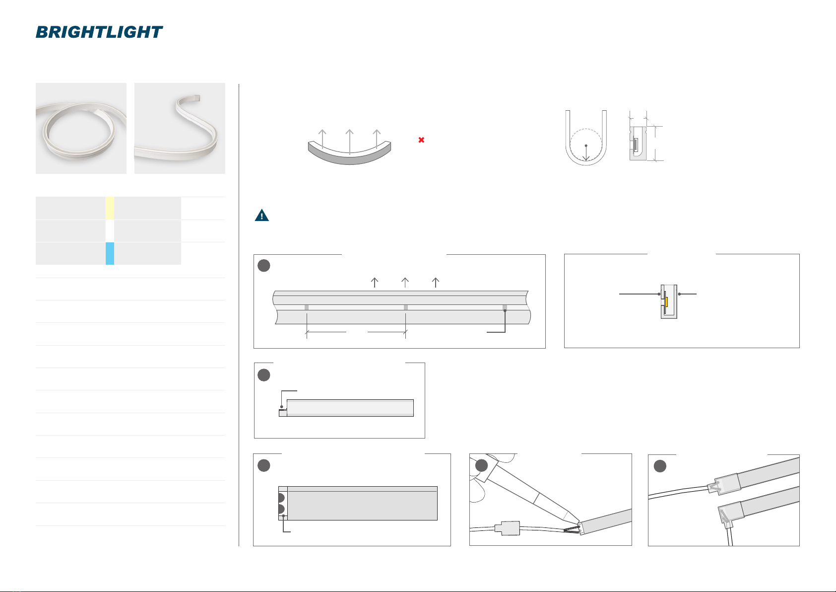
MINIMUM BEND
RADIUS
10mm
BEND DIRECTION Horizontal bending
SOURCE LIFE 50,000 hours
WARRANTY 3 years
INGRESS
PROTECTION
Protection established by use of
IP66 connections
CONTROL Dimmable by PWM signal
1. Cut Encapsulated LED Ribbon only
at the cut lines shown on Side A of
product.
2. To t a connector: cut out a notch
(approx 3 × 3mm) from Side B to
expose the PCB solder pads. Take
care not to cut or damage the PCB
and LEDs in this step.
SIDE A
Cut mark are
visible on this side
SIDE B
When connecting cable,
notch out from this side
CUT OUT NOTCH TO EXPOSE SOLDER PADS
TOP VIEW - EXPOSE SOLDER PADS
CUT MARK
TOP / LIGHT DIRECTION
50
SIDE A VIEW - CUT MARKS CROSS SECTION
SIDE B VIEW - EXPOSE SOLDER PADS
1
2A
2B
3. Cut and trim the cable to the appropriate length and feed
through connector. Solder the wires onto the solder pads of the
Encapsulated LED Ribbon PCB ensuring the correct +/- polarity.
4. Insert silicone into connector before tting over connection. The
silicone is required to complete the IP66 rating. Failure to do this
will result in warranty becoming void.
5. Shortening ribbon / tting new end cap: Cut Encapsulated
LED Ribbon to length then t end cap and silicone in place.
SAFETY NOTES
–Before making any cuts, installation,
maintenance, or connection, be sure
the mains power is disconnected.
–All connector joints must be connected
correctly to achieve connector IP rating.
–Check the polarity of the connector
before inserting the front connector and
switching on the mains power.
–Cut and connect Encapsulated
LED Ribbon correctly. Any incorrect
operation can cause damage.
–Use a certied Bright Light 24V DC
power supply.
ENCAPSULATED LED RIBBON | LITE CAN BE CURVED AS SHOWN BELOW:
CUT OUT NOTCH TO EXPOSE
SOLDER PADS
DO NOT TWIST THE LIGHT
OR BEND AGAINST THE
LIGHT SURFACE
0800 952 000 | www.brightlight.co.nz | BRIGHTLIGHT
12
6
CUTTING RIBBON & CONNECTING BOOT CONNECTORS
ADD SILICONE
INTO CONNECTOR
BEFORE FITTING
SOLDER WIRES SILICONE CONNECTOR
34
BRIGHT LIGHT RECOMMENDS CONNECTIONS ARE MADE IN-HOUSE
MINIMUMBENDRADIUS
10MM
LIGHT DIRECTION
HORIZONTAL BENDING


