Brightline BL.16 User manual

BL.16
Operating Instructions
580 Mayer Street, Building #7, Bridgeville, PA 15017 phone 412.206.0106 fax 412.206.0146 www.brightlines.com
2018 Brightline, L.P.
1

The Brightline BL.16 is a 42-watt, energy-efficient light fixture. This fixture combines
high-frequency electronics with a state-of-the-art optical system to produce a soft, full-spectrum,
flicker-free light source.
Owner’s Record
Product Description
Safety
Warning: Do not dim a non-dim fixture.
Do not service fixture until the appropriate service
manual has been read and the unit has been
completely de-energized.
All fixtures are fuse protected.
To prevent fire or shock hazard, do not expose
the unit to water or moisture.
Do not operate fixture without LED’s installed.
Operating the fixture without the lamps installed
may result in damage to the driver.
Service on the unit should be performed only by
a qualified technician.
In case of LED failure:
1. Turn fixture “OFF”.
2. Wait 30 seconds for driver to reset.
3. Turn fixture “ON”.
Model No.________________________
Serial No.________________________
Date of Purchase__________________
The serial number of this product can be found on the side of the main housing. You should note
the model number and the serial number in the space provided and retain this book for future
reference as a permanent record of your purchase.
2

Installing the Yoke
1. Assemble palm handle, yoke, and washers
as shown (Fig. 1).
Figure 2
2. Screw palm handle into place (Fig. 2).
3. Repeat Steps #1 and #2 for remaining
palm handle.
1. While firmly grasping fixture, loosen palm
handles (Fig. 3).
2. Adjust tilt of fixture, as desired.
3. Retighten palm handles.
Figure 3
Adjusting the Yoke
Figure 1
Palm
Handles
3

Exploded Assembly
- BaffleNekoY-A
hctaLyrosseccA-OrehsaWkroC-B
PrehsaWnolyN-C - Display
D - Yoke Palm Handle Q - Power Bracket
RelcatpeceR-E - Lens?
F - Power Inlet Module with Fuse S - Reflector
Light Engine-ThctiwSrekcoR
-G
H - Male 5 Pin XLR Receptacle U - 6-32 Nut
I - Female 5 Pin XLR Receptacle V - Nylon Spacer
-WgnisuoHtsallaB-J 4-40 x .31, Phil, Flat
-X- Power SupplyK 6-32 x .25 Lg. Screw
Keps Nut23-6-YrotrevnoClangiS-L
wercSedixOkcalB52.x23-6-Zgn
isuoHniaM-M
BL.16X1
BL.16X1
F
E
W
G
HI
J
V
N
U
P
L
Q
D
A
C
B
K
O
M
Z
R
T
S
4

Notes
Figure 7
Installing Adapters (C-Clamp/Spud)
Figure 6
1. Thread mounting screw through yoke and
into adapter (Fig. 6).
2. Tightly fasten mounting screw in place (Fig. 7).
C-Clamp
1/2” Lock
Washer 1/2-13 UNC
Hex Bolt
5

DMX Cable Layout
DMX Networking Guidelines
If you are connecting more than one DMX fixture, it is imperative to properly configure the DMX network. Following
the guidelines below should reduce the possibility of networking errors.
1. Fixtures and other devices in a DMX network need to be configured in a daisy-chain fashion. The use of DMX "Y"
devices or "twofers" is not appropriate.
2. You can use up to 32 Brightline DMX fixtures on a single DMX data line. If there are more than 32 units, the use
of a DMX repeater amplifier or splitter amplifier is required. A repeater amplifier is an electronic device that
boosts the DMX signal. A splitter amplifier is an electronic device that boosts the DMX signal and provides
for multiple DMX outputs from a single DMX input (since using multiple DMX devices may cause signal
degradation).
3. With most DMX devices, there is a "DMX Thru/DMX Terminate" switch that is set to "Terminate" for the last
device on the data line and set to "Through" for all other devices. Brightline DMX fixtures are self-terminating, and
thus this switch is not provided.
4. Brightline fixtures, like the majority of DMX devices, use 5-pin, XLR-type plugs wired according to Table 1.
Pins 4 & 5 are not used, and so, on Brightline fixtures, are not connected. Pin 1 (shield) should be connected to
earth ground only at the control console.
5. Only cables intended for DMX operation should be used. Avoid DMX runs parallel to power cables, particularly
those from dimmer racks.
Note: These guidelines will help the user configure most DMX networks. For more information, contact the
manufacturer of the control console, or a DMX manual. A useful DMX guide is "Recommended Practice for
DMX-512" by Adam Bennette, co-published by PLASA in the United Kingdom and USITT in North America.
Table 1
MTX Cable
To Next Fixture
Lighting Control
Console
XLR Pin Num- DMX Wire
1
2
3
Common
DMX -
DMX +
4
5
Not Used
Not Used
6

1. Swing latch open (Fig.8).
Figure 8
2. Insert accessory into the track and
slide it forward until it stops (Fig. 9).
3. Swing latch closed and fasten in place (Fig. 10).
Figure 10
Installing Accessories
Figure 9
Latch
7

Disconnecting Cables
1. Turn power “OFF” on all devices.
Note: If the fixture power is not turned “OFF” before
connecting or disconnecting the DMX cable to the
fixture, damage to the ballast may result.
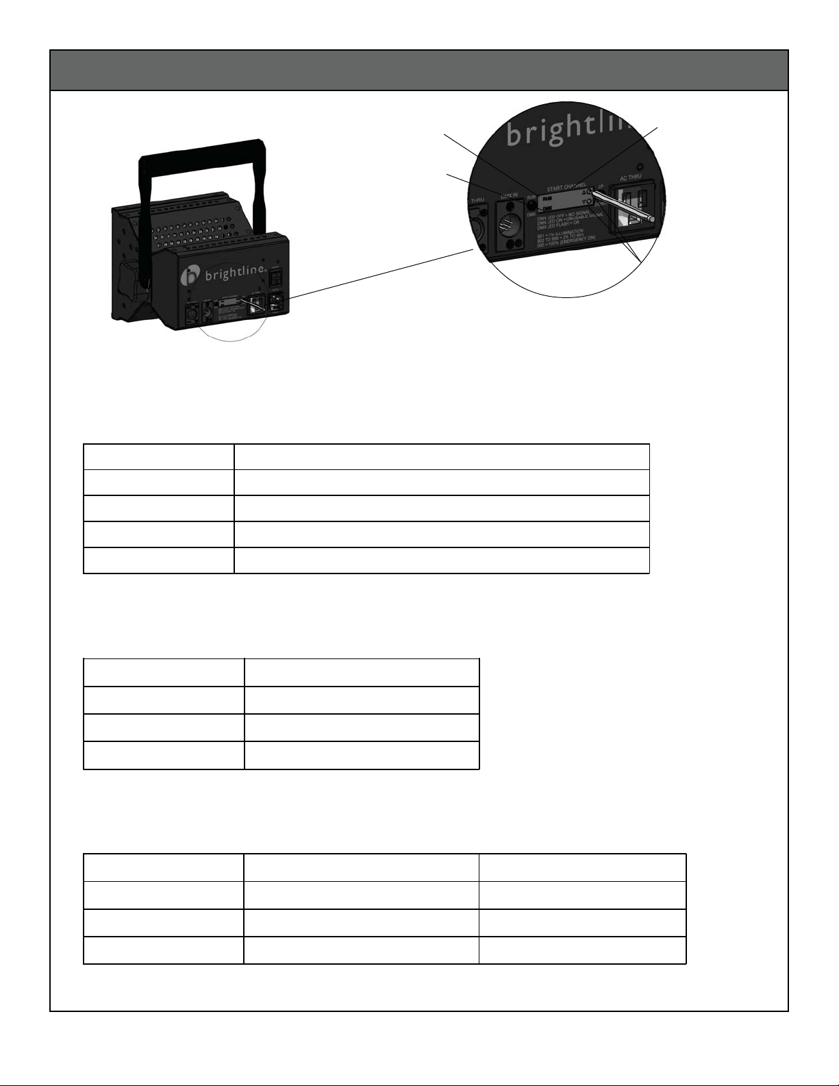
2. Insert the male plug end (Figure 1) into the appropriate
female receptacle on the lighting control console.
3. Line up the locking key on the female plug end (Figure 2)
with the male receptacle on the first fixture labeled
“DMX IN.” Insert the plug into the receptacle until it
locks into place.
4. To add additional fixtures, line up the locking key on the
male plug end of the jumper cable (Figure 1) with the
female receptacle labeled “DMX THRU” on the first
fixture. Insert the plug into the receptacle until it locks
into place.
5. Route the jumper cable to the next fixture.
6. Line up the locking key on the female plug end of the
jumper cable (Figure 2) with the male receptacle
labeled “DMX IN” on the next fixture. Insert the plug
into the receptacle until it locks into place.
7. Repeat Steps 4-6 for remaining fixtures.
8. Turn power “ON” on all devices.
Installing DMX Control Cables
Figure 5 Figure 6
3. To disconnect the male end of cable, press in the
release button on the female receptacle (Figure 5) and
pull the plug out of the receptacle (Figure 6). Pressure
should be applied to the plug, not the cables.
Figure 1 Figure 2
Locking Key
1. Turn power “OFF” on all devices.
2. To disconnect the female end of cable, press down the
release button on the plug (Figure 3) and pull the plug
out of the receptacle (Figure 4). Pressure should be
applied to the plug, not the cables.
Figure 3 Figure 4
8

1. The IEC320 connector mates with the
power inlet module (Fig. 13).
Note: The ON/OFF switch should always be
in “OFF” position when installing or
removing the power cord.
Installing Power Cord
Replacing Fuse
1. Pull fuse holder out of power inlet module.
2. Remove fuse holder and check for wear (Fig. 11).
If fuse is blown, replace with a new fuse or the
on-board spare (Fig. 12).
3. Return fuse holder to a closed position.
Figure 11
Figure 13
Note: Replace fuse only with 8-amp, time-delay,
250-volt, 5 x 20-mm fuses.
On-board Spare
Active Fuse
Figure 12
9

Reading the LED Display
Figure 7
Fixture Status Indicator
DMX Signal Indicator
Channel Indicator
Adjustment
Buttons
Note: Fixtures are supplied with onboard memory capabilities that retain the fixture’s last setting.
1. The channel indicator is used to determine the setting of the fixture in the following modes:
a) Emergency On Mode: Fixture is manually operating at 100% b) Manual Dimming Mode: Fixture is
manually dimmed at LED display without the use of a lighting control console. c) Console Dimming Mode:
Fixture is set to a DMX address for dimming by the use of a lighting control console. Use Table 2 to evaluate
the readout of the channel indicator on the LED display (Figure 7).
2. The DMX signal indicator is used to determine whether the fixture is receiving a DMX signal while in the
Console Dimming Mode. The lighting control console and all necessary DMX cabling must be installed. Use
Table 3 to evaluate the readout of the DMX signal indicator on the LED display (Figure 7).
3. The fixture status indicator is used to determine whether the changes being made to the settings at the LED
display are completely processed. Use (Table 4) to evaluate the readout of the fixture status indicator on the
LED display (Figure 7). Any changes made to the settings will require a few seconds to be processed.
Table 2
Table 3
Table 4
DMX Signal Indicator DMX Signal Status
DMX LED Off No Signal
DMX LED On Unuseable Signal
DMX LED Flashing Signal OK
Channel Indicator Description
000 Emergency ON/Fixture at 100%
001-512 DMX Address for Lighting Control Console
513-899 Not Available
900-999 Manual Dimming (1% Increments, 900 = OFF, 925 = 25%, etc.)
Fixture Status Indicator DMX Signal Present Emergency On/Manual Dimming
Run LED Off Processing Changes to Settings Processing Changes to Settings
Run LED On Settings completely processed Not Available
dessecorpyletelpmocsgnitteSelbaliavAtoNgnihsalFDELnuR
10

Clean reflector with a dry, non-abrasive cloth.
Troubleshooting Guide
Maintenance
Replace fuse only with 8-amp, time-delay,
250-volt, 5 x 20-mm fuses.
noituloSesuaCelbissoPmelborP
LED’s are flashing or
strobing.
Wrong voltage for driver
installed.
Verify that the driver's voltage is
correct.
Driver buzzes or hums. Defective driver. Identify location of buzz and replace
driver if necessary.
Light fixture does not turn
"on."
Defective or missing fuse. Install fuse into power entry module.
11

Setting the DMX Address
DMX Troubleshooting Guide
Figure 8
1. Program DMX addresses by gently pressing in the adjustment buttons with
a pointed object such as a pen (Figure 8).
2. Use Channels 001 thru 512 to program the DMX addresses for the lighting
control console. Program the DMX address on the fixture to match the
desired channel at the lighting control console.
(Example: 001 = channel 1, 002 = channel 2, etc.)
3. A fixture can be programmed for individual control by setting the DMX
address exclusively to a single fixture. Multiple fixtures can be set to the
same DMX address to control a group of fixtures on a single channel at
the lighting control console.
noituloSesuaCelbissoPmelborP
No DMX signal on all
fixtures in DMX system.
1. Lighting control console power is
turned "OFF."
2. Cabling or connection problem
between lighting control console and first
fixture in DMX system.
1. Turn lighting control console power "ON."
2. Check connections at first fixture and lighting
control console or try another DMX cable.
No DMX signal on a single
fixture or group of fixtures
in the DMX system.
Cabling or connection problem with
jumper cable.
Check connection of jumper cable between
fixture with no signal and previous fixture in DMX
system or try another DMX jumper cable.
Fixture is turned "ON" and
cannot be dimmed at
lighting control console.
1. Fixture is set to "Emergency ON"
mode or "Manual Dimming" mode.
2. Cabling or connection problem and
fixture is remembering last setting.
1. Set DMX address at fixture to match desired
channel at the lighting control console.
2. Check cabling and connections in DMX
system.
Unusable DMX signal.
1. Cabling problem.
2. Start channel is set higher than number
of channels transmitted by lighting control
console.
1. Check the wiring in DMX cable plug ends.
The DMX + and DMX - wires may be crossed.
2. Set start channel lower to accommodate the
number of channels transmitted by the lighting
control console.
Fixture Status Indicator
DMX Signal Indicator
Channel Indicator
Adjustment
Buttons
12

Specifications
LED : 16 CREE XP.E 3200°K or 5600
50,000-hour-rated lamp life.
Housing: 14-gauge (.060) formed,
aluminum sheet-metal construction.
See finish note.
Mounting: 10-gauge (.125) extruded-aluminum
yoke, welded construction (standard).
2” O.D. pipe clamp or TVMP adapter provided.
Power Entry Module: 8-amp fuse
(with on-board spare) and IEC connector
incorporated within housing.
Finish: Low glare, polyester powder coat.
Switch: Rocker ON/OFF power switch.
Optional Accessories: Fixture screens,
snoot, and gel frame.
Power Cord: 12’ length, 3/18 gauge SOW cable
10 amp/250 V. IEC320 connector to grounded
Edison (3) prong plug - NEMA 5-15P standard.
(Optional connectors available upon request.)
Black finish.
A - Palm Handle
B - Ballast Housing
C - Driver
D - Zip tie
E - #6-32 Nut
F - Housing
H - Baffle
I - Reflector
J - Nylon Spacer
K - #6-32 x .31 lg. Screw
L - #6-32 Nut
M - #4-40 X .38 lg. Screw
N - Latch
O - #6-32 screw
P - Nylon Washer
Q - Cork Washer
R - Rocker Switch Power
S - Power Inlet Module
T - Receptacle
U - Yoke
V - Wire Guard Bracket
Exploded Assembly
°K
R
B
J
H
O
I
N
K
L
QA
T
C
FZ
E
D
U
S
P
BL.16P
13

Patent Pending
Brightline guarantees all its products to be free from defects in materials and
workmanship for a period of three (3) yearsfrom the date of shipment.
If any product is found to be unsatisfactory under this warranty, the buyer must notify
Brightline immediately. Once a course of action has been determined, if it is
necessary to return the product to Brightline a Return Authorization (RA) will be
issued. Ship the product directly to Brightline , 580 Mayer Street, Building #7,
Bridgeville, PA 15017. The RA number should be marked on the shipping carton. The
unit will be replaced or put into proper operating condition, free of all charges. The
correction of any defects through repair or replacement by Brightline shall
constitute fulfillment of all obligations and liability of Brightline to the buyer under
this warranty and the contract of sale.
Brightline is not responsible for damage to its products caused by improper
installation, maintenance, or use; by improper electrical hookups; or by unauthorized
repairs.
Failure to notify Brightline of unsatisfactory operation or any improper or
unauthorized installation, maintenance, use, repairs, or adjustments shall terminate the
warranty and Brightline shall have no further responsibility under the warranty.
Brightline shall not be liable for special or consequential damages in any claim,
action, suit, or proceeding arising under this warranty or contract of sale, nor shall
Brightline be liable for claims for labor, loss of profits or goodwill, repairs, or other
expenses incidental to replacement. Brightline makes no other warranty of any
kind whatsoever, expressed or implied, and all implied warranties of merchantability and
fitness for a particular purpose that exceed the obligation specifically described in this
warranty are hereby disclaimed by Brightline and excluded from this agreement.
All shipments, unless otherwise noted, are F.O.B. factory.
The customer is advised to inspect for shipping damage, apparent and/or hidden.
If detected, notify the transportation company and file your claim.
WARRANTY
PROCEDURES
DISCLAIMERS
580 Mayer Street, Building #7, Bridgeville, PA 15017 phone 412.206.0106 fax 412.206.0146
www.brightlines.com
14

Notes
15
This manual suits for next models
1
Table of contents
Other Brightline Floodlight manuals
Popular Floodlight manuals by other brands

Stairville
Stairville MH-575 S MKII Pro-Spot user manual

Regent
Regent CSMV80W instruction manual

PEWA
PEWA Steinel HS 5140 operating instructions

Equinox Systems
Equinox Systems Revolution EQLED80 user manual

NORDRIDE
NORDRIDE 4310-10 operating instructions

Triangle Lights
Triangle Lights LED PAR64 18W 6CH LCD Sound user manual