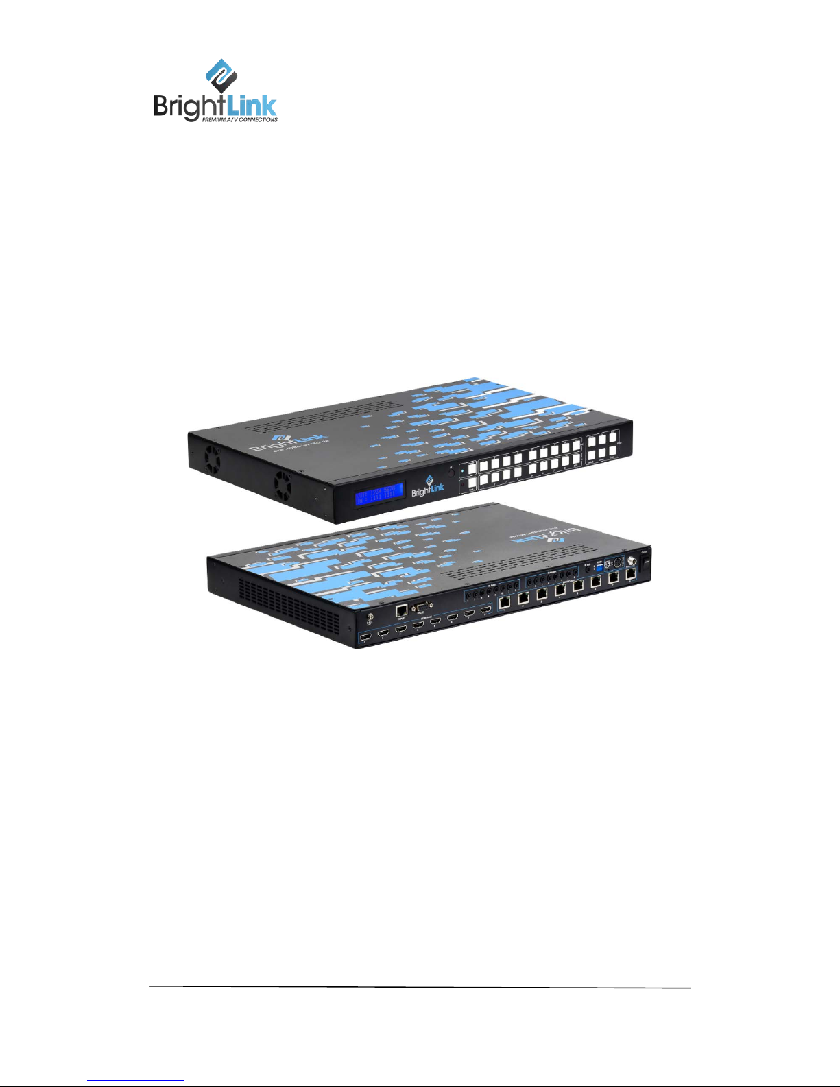
BL0808-HDBT-1 User manual
Brightlink Cables LLC Contact: support@brightlinkcables.com 2
Thank you for purchasing this product. For optimum performance and safety, please read these
instructions carefully before connecting, operating or adjusting this product. Please keep this
manual for future reference.
SURGE PROTECTION DEVICE RECOMMENDED
This product contains sensitive electrical components that may be damaged by electrical
spikes, surges, electric shock, lightning strikes, etc. Use of surge protection systems is highly
recommended in order to protect and extend the life of your equipment.
***SAFTY AND NOTICE - MUST READ***
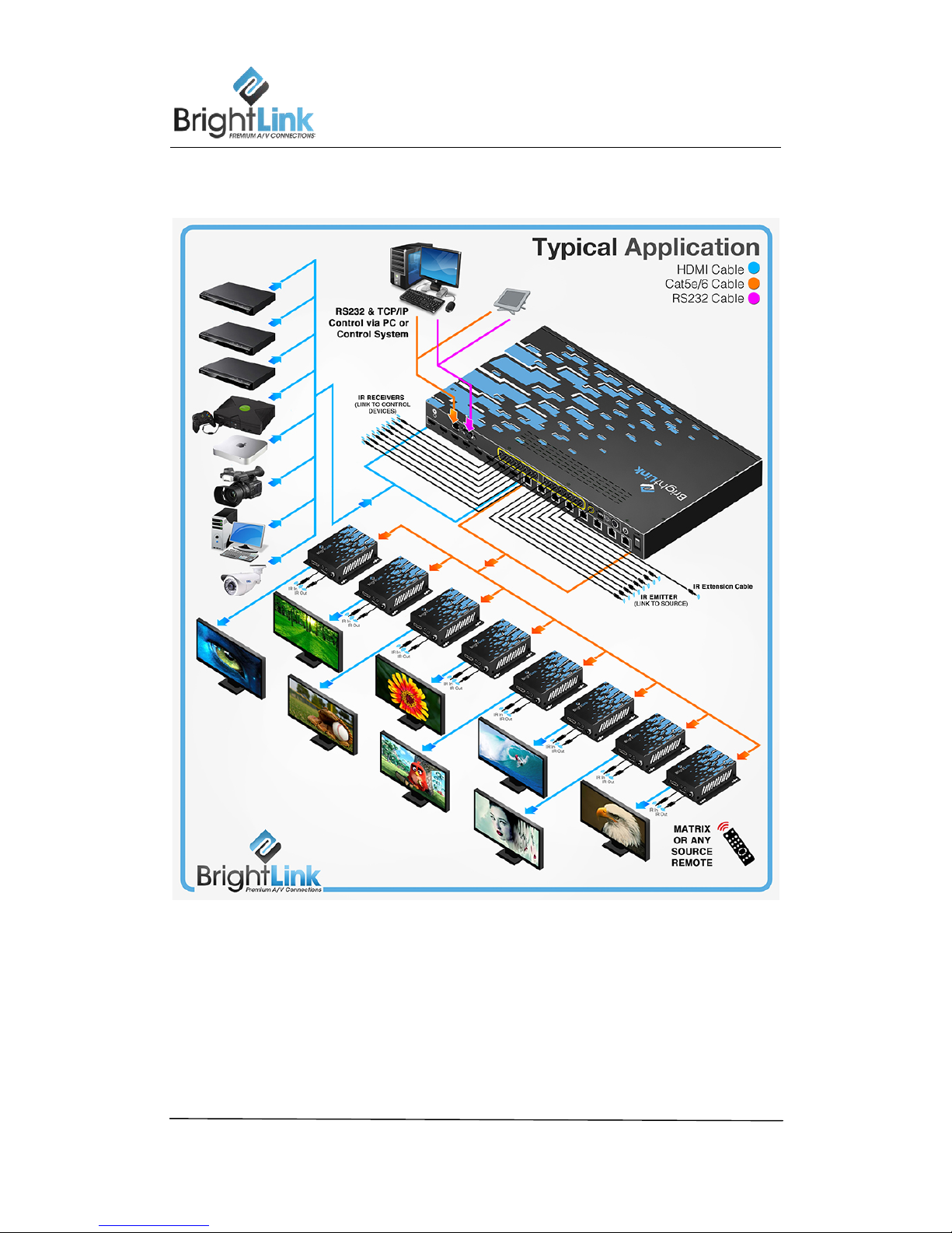
1. The transmission distances of HDMI over UTP cables are measured using TE
CONNECTIVITY 1427071-6
2. EIA/TIA-568-B termination (T568B) for CAT cables is recommended for better
performance.
3. DO NOT use 568A/568B standard mixed CAT cable (cross-over cable) because there are
2 pairs swapped, this will make POE OVER-CURRENT and damage POE components.
Please use straight-through CAT cable (both RJ45 headers are 568A or 568B standard).
4. It is recommended to power up the devices after connecting the sources, sinks and CAT
cable.
5. To reduce the interference among the unshielded twisted pairs of wires in the CAT cable,
do not run HDBaseT / Zone Cat5e/6/6a cabling with or in close parallel proximity to mains
power cables. Shielded CAT cables can be used to improve EMI problems, which is worsen
in long transmission.
6. Because the quality of the CAT cables has a major effect on how long until the
transmission limit is reached and how good the received picture quality is, the
actual transmission range is subject to one’s choice of CAT cables.
7. Do not substitute or use any other Power Supply other than the enclosed unit, or a
Brightlink approved Replacement Part. Doing so will void the warranty and potentially
expose the user to dangerous voltages resulting in an electrical shock.
8. Do not disassemble the device for any reason. Doing so will void the manufacturer’s
warranty. Also, our unique case is an integral part of the design of this unit and is
responsible for cooling and circuitry shielding. Any modifications to this case will potentially
cause malfunction and product failure.
9. Do not expose the device to water, moisture, or liquids. Possible electric shock may result
as well as failure of the unit to operate.