Brightlink PRO-MIX BL-8X8-HDBT User manual

BRIGHTLINK PRO-MIX 70m 8x8 / 8x16 HDBaseT
Matrix Set c/w 8 receivers. Support POC/POE, IP
Control, RS232 Control and 8 mirrored HDMI
output.
Model: BL-8X8-HDBT
Operating Instructions
BRIGHTLINKAV.COM
1

Operating Instruction
Thank you for purchasing this product. For optimum performance and
safety, please read these instructions carefully before connecting,
operating or adjusting this product. Please keep this manual for future
reference.
SURGE PROTECTION DEVICE RECOMMENDED
This product contains sensitive electrical components that may be
damaged by electrical spikes, surges, electric shock, lightning strikes,
etc. Use of surge protection systems is highly recommended in order to
protect and extend the life of your equipment.
2

Operating Instruction
Table of Contents
1. Features.....................................................................................4
2. Package Contents.....................................................................4
3. Specifications............................................................................4
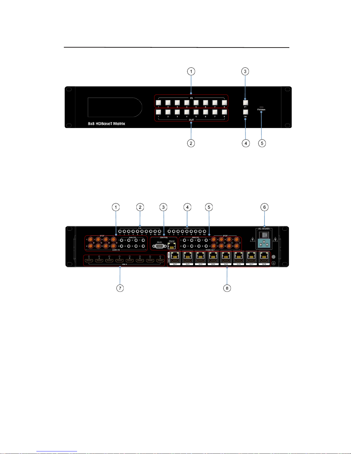
4. Panel Descriptions....................................................................5
4.1 Input / output channel key operation...........................................6
4.2 Video switching operation .........................................................6
4.3 COPY EDID of HDMI Display.......................................................6
4.4 COPY EDID of HDBaseT output..................................................7
4.5 Inlay(built-in) A selection...........................................................7
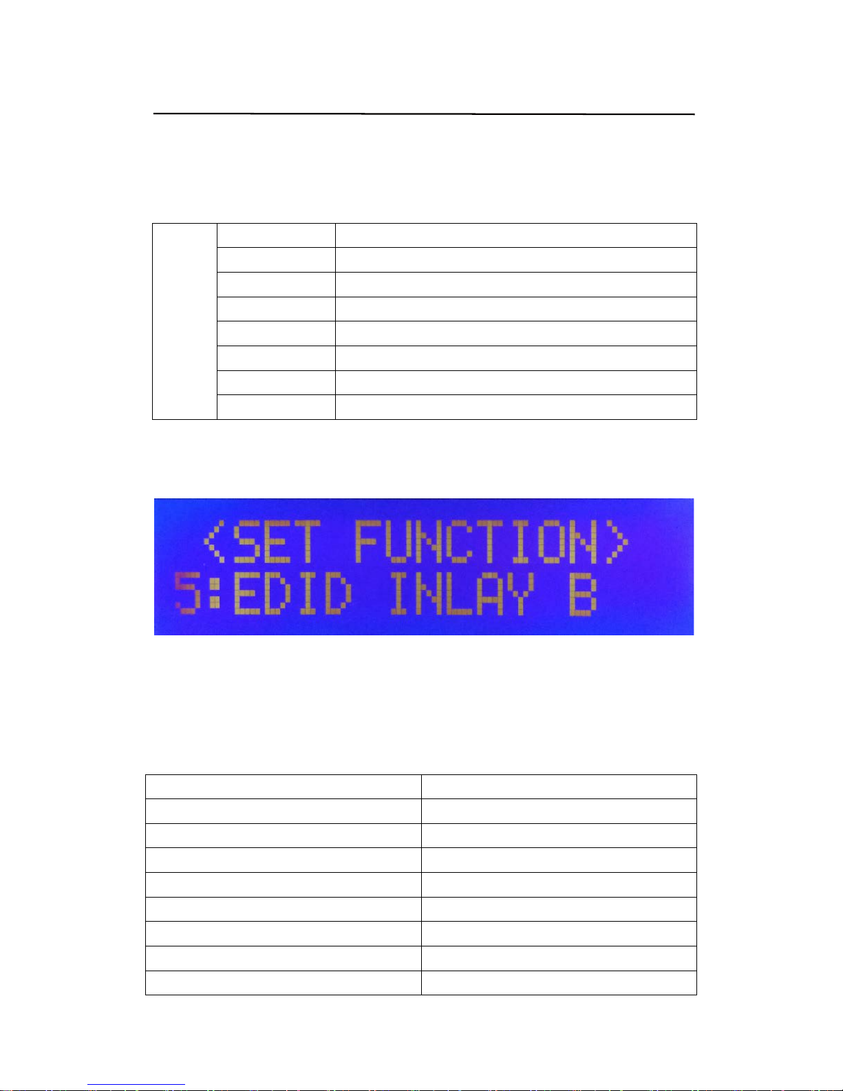
4.6 Inlay(built-in) B selection...........................................................8
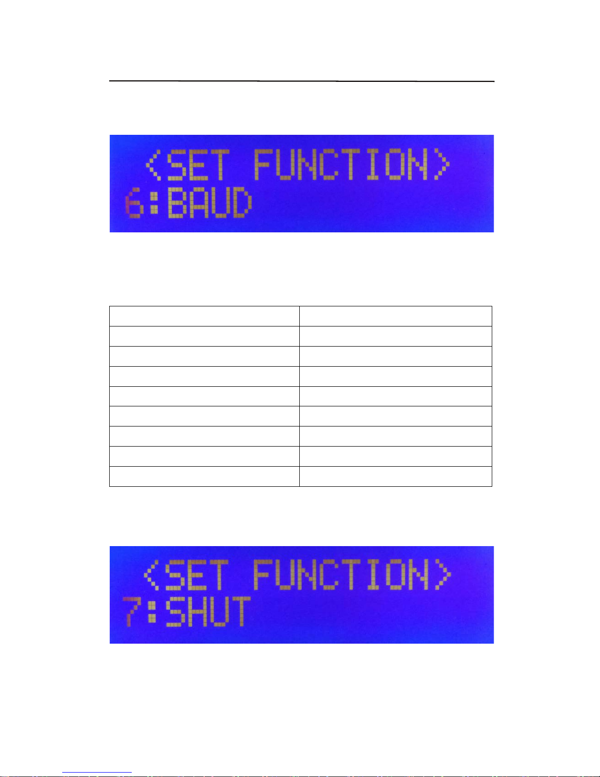
4.7 Baud Rate Settings ...................................................................8
4.8 Timing shutdown Function ........................................................9
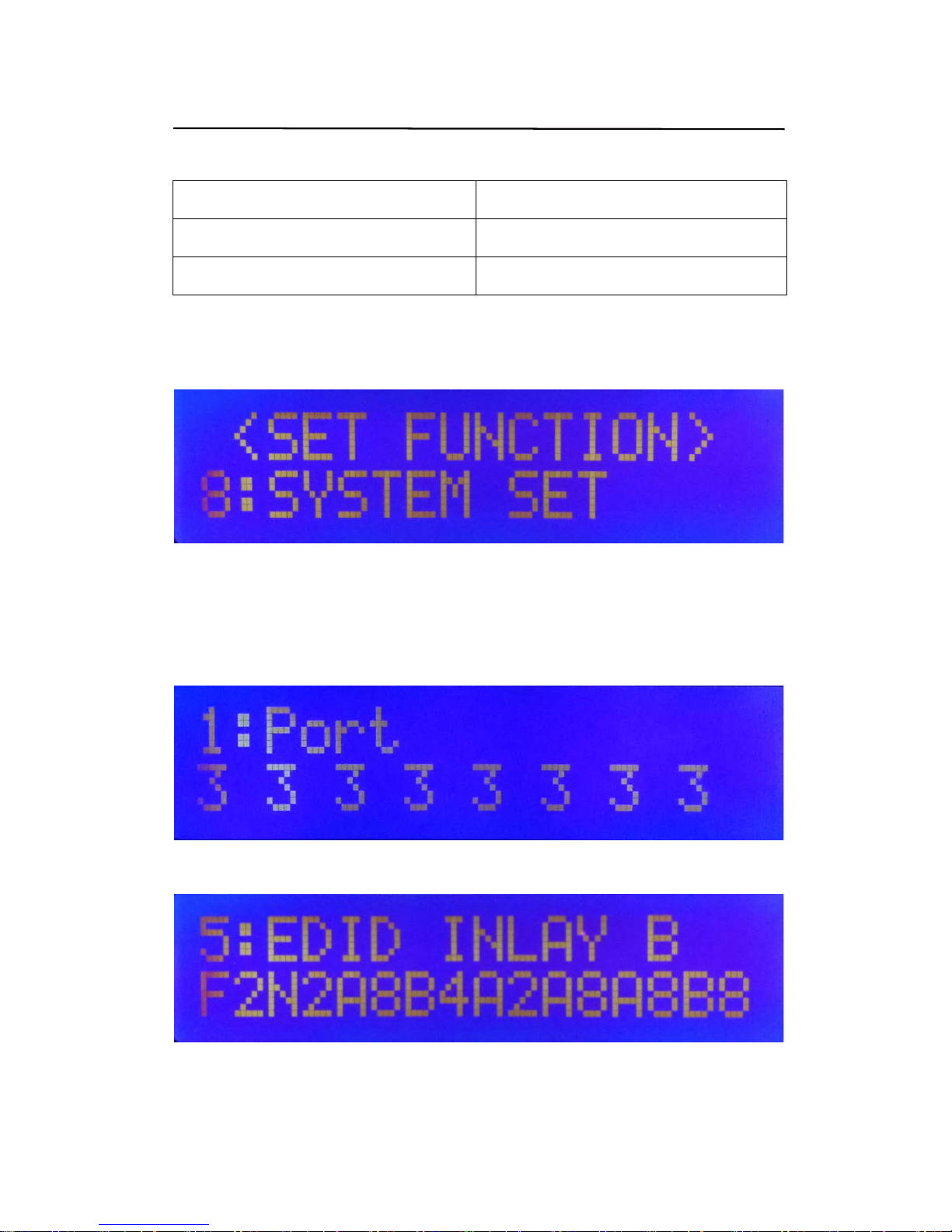
4.9 System Settings......................................................................10
4.10 Check information for Output.................................................10
4.11 Boot/Standby interface...........................................................11
5. Connecting and Operating......................................................11
6.Application Diagrams..............................................................12
7. Remote Control Description...................................................12
8. IR system.................................................................................13
9. RS232 Control..........................................................................14
9.1 Software Control.....................................................................14
9.2 Command Control...................................................................16
10. Web Control...........................................................................17
10.1 Change the IP address of your PC............................................17
10.2 Enter Web and Control...........................................................18
11. Audio Introduction................................................................20
12. RS232 Pass through.............................................................20
13. USB Online upgrading Firmware.........................................20
Warranty Policy............................................................................21
3

Operating Instruction
Dear Customer
Thank you for purchasing this product. For optimum performance and safety, please read
these instructions carefully before connecting, operating or adjusting this product. Please
keep this manual for future reference.
1. Features
Incorporates HDBaseT technology
Send any one of the 8 HDMI Sources to any one of the 8 HDMI Displays
Each of the 8 outputs includes one HDMI output and one UTP output simultaneously
HDMI 1.4 version (Support HDMI1.4 4K@60Hz YUV4:2:0).
Transmit up to 70m under 1080p,40m under 4K@60Hz.
HDCP 2.2/1.4 compliant.
Uses wide-band Bi-Direction IR routed control(38~56KHz)
Support RS232 pass through
Support 8x Analog Audio and 8x SPDIF Audio embedded,
Support 8x Analog Audio and 8x SPDIF Audio extraction.
Support Panel Button, IR Routing, RS232 Control, IP Control
Support POC (Receiver powered by HDBaseT Matrix).
2U rack design with mounting ears
2. Package Contents
1). 1x Main Unit (HDBaseT Matrix)
2). 1x Power Cable (AC100-240V)
3). 1x Remote control
4). 1xIR Extension cable, 10x Wide-Band "IR in " Cables, 9x "IR out" Cables
5). 1x mounting kit
6). 1x CD for control software & user manual
3. Specifications
Operating Temperature Range
-5 to +40°C(23 to +104 °F)
Storage Temperature Range -10 to +60°C(-14 to +140 °F)
Operating Humidity Range
5 to 90 % RH (no condensation)
Input Video Signal
0.5-1.0 volts p-p
Input DDC Signal 5 volts p-p (TTL)
Signaling Rate 10.2Gbit/s
Video Format Supported 4K@60Hz,YUV420
4k@30Hz/1080P/1080i/720P/576P/480P/576i/480i
HDCP Compliant
HDCP2.2 and HDCP1.4
Output Video
HDMI2.0 and HDMI 1.4 (over HDBaseT)
Audio Format Supported PCM, Dolby5.1/7.1, DTS5.1/7.1 digital audio
Maximum Transmission Distance 1080P 70m, 4K 40m
Power Consumption 48wtts (Max.)
Dimensions L482.6 x W397.2 x H88 mm
Mass (Main Unit)
7.5KG
4

Operating Instruction
4. Panel Descriptions
①Input button IN1~8: choose the desired input port from ports 1~8 in video mode.
②Output button OUT1~8: choose the desired output port from ports 1~8 in video mode.
③F1 button: Function button (please refer to 4.1).
④OK button: Confirm or Clear
⑤USB Port for Firmware upgrade.
①Audio IN port (SPDIF & ANALOG)
②IR IN port.
③RS232 & Ethernet for control.
④IR OUT port.
⑤Audio OUT port (SPDIF & ANALOG)
⑥Power ON/OFF
⑦HDMI Input ports (1~8).
⑧HDMI/HDBT Output ports (1~8).
5

Operating Instruction
4.1 Input / output channel key operation
Channel Button method
Any Key The first operation of the button can wake up the screen
Input8 In EDID mode, long press means select all the channels
Output8 In Video mode, long press means select all the output channels
F1
Long press: enter the function selection mode
short press: check the status of mode
OK Short press: confirm
Long press: clear the number selection key
F1+OK Lock the panel operation , press again to unlock
4.2 Video switching operation
Specific operations are as follows
①Long press the F1 key and select input 1 (video switch), press the "OK" key, enter the
video switching mode
Video switching mode (picture 1)
②Switch the input to the output
Operation format: "input channel" + "output channel" + "OK"
4.3 COPY EDID of HDMI Display
Specific operations are as follows
①Long press the F1 key, select input 2 (HDMI EDID copy), press the "OK" key, enter the
copy EDID mode.
②Select the corresponding output EDID and copy to the input, the selected channel will
automatically read EDID of the HDMI Display (such as TV).
HDMI EDID copy mode (picture 2)
6

Operating Instruction
③Copy output EDID to the input
Operation format: "input channel" + "output channel" + "OK".
4.4 COPY EDID of HDBaseT output
Specific operations are as follows
①Long press the F1 key, select input 3 (HDBT EDID copy), press the "OK" key, enter the
copy EDID mode.
②Select the corresponding output EDID copy to the input, the selected channel will
automatically read EDID of the HDMI Display (such as TV).
HDBT EDID replication mode (picture 3)
③Copy output EDID to the input
Operation format: "input channel" + "output channel" + "OK""
4.5 Inlay(built-in) A selection
The built-in EDID A
The built-in EDID A includes 8 options as follows:
INLAY A
OUT1 4K60-420-2D-2.0(Default EDID)
OUT2 4K60-420-2D-5.1
OUT3 4K60-420-2D-7.1
OUT4 4K60-2D-420
OUT5 4k30-2D-2.0
OUT6 4k30-2D-5.1
OUT7 4k30-2D-7.1
OUT8 LENOVO 4K30
Specific operations are as follows
①Long press the F1 key, select input 4 (Inlay A), press the "OK" key, enter the built-in
EDID mode
Built in EDID mode (picture 4)
7

Operating Instruction
②Select built-in EDID to the input
Operation format: "input channel" + "output channel" + "OK".
4.6 Inlay(built-in) B selection
The built-in EDID B includes 8 options as follows:
INLAY B
OUT1 1080P-2D-2.0
OUT2 1080P-2D-5.1
OUT3 1080P-2D-7.1
OUT4 1080P-3D-2.0
OUT5 1080P-3D-5.1
OUT6 1080P-3D-7.1
OUT7 1080P-2D-LPCM2.0
OUT8 720P-2D-2.0
The specific operation is as follows:
①Long press the F1 key, select input 5 (Inlay B), press the "OK" key, enter the built-in
EDID mode
Built in EDID mode (picture5)
②Select built-in EDID to the input
Operation format: "input channel" + "output channel" + "OK"
4.7 Baud Rate Settings
Baud rate setting includes following eight options:
Corresponding output port Baud rate parameter
OUT-1 115200(Default)
OUT-2 2400
OUT-3 4800
OUT-4 9600
OUT-5 19200
OUT-6 38400
OUT-7 57600
OUT-8 115200
8

Operating Instruction
Specific operations are as follows
①Long press the F1 key, select input 6 (baud rate settings), press the "OK" key, enter the
baud rate setting mode.
Baud rate setting (picture 6)
②Select baud rate to the corresponding output channel and press “OK” to confirm.
4.8 Timing shutdown Function
Timing shutdown setting includes eight options as follows:
Corresponding output port Shutdown time (hours / min)
OUT-1 NONE
OUT-2 00H05M
OUT-3 00H10M
OUT-4 00H30M
OUT-5 01H00M
OUT-6 03H00M
OUT-7 12H00M
OUT-8 24H00M
Specific operations are as follows
①Long press the F1 key, select input 7 (timing shutdown settings), press the "OK" button,
enter the timing shutdown mode
Timing shutdown settings (picture 7)
②Select the shutdown time to the corresponding output channel, and press “OK” to
confirm.
9

Operating Instruction
4.9 System Settings
System setting includes two options as follows:
Corresponding outlet Setting details
OUT-1 Reboot
OUT-2 Factory reset
The specific operations are as follows:
①Long press button “F1 ”and select input 8 (system Settings) ,press "OK" ,enter the
system settings mode .
System Settings (picture 8)
②Press Output from 1-2, select set reboot or factory reset for the corresponding output
channel, press "OK" to confirm.
4.10 Check information for Output
Long press button “F1 ”to check information for the output .(such as video switch/EDID)
Check Output channel (picture 9)
Check EDID channel (picture 10)
10

Operating Instruction
EDID channel nouns explanation :
A Inlay A User (built-in EDID A)
B Inlay B User (built-in EDID B)
F Far-end Far end (HDBT)
N Ring-out Loop out (HDMI)
The specific operations are as follows:
①In video switch mode, input/output EDID mode , short press “F1 ” to check the current
output status.
②After the checking, press the button "OK" to exit the mode.
4.11 Boot/Standby interface
The key time interval is no more than 60 seconds. If over 60 seconds, the LCD screen will
automatically enter the backlight mode and return to the video channel main interface.(the
default time is 60 /LCD backlight brightness is100, this can be set by the commands)
Boot/standby main interface (picture 11)
5. Connecting and Operating
1). Connect the HDMI input sources (such as HD-DVD, PS3, STB etc) into HDBaseT
Matrix.
2). Connect Cat5e/6 cable to HDBaseT output port of HDBaseT Matrix and HDBaseT
input of Receiver.
3). Connect HDMI sink devices (such as HD-LCD, HD-DLP) to the Receiver.
4). Power on the input source you want to show.
5). Connect the power cable into HDBaseT Matrix and turn on the display you want to
watch.
6). Use remote or push the button to choose input source.
*Note: Do not dispart the machine when power on because there is 220V AC power
inside the machine!
11

Operating Instruction
6. Application Diagram
Remote Control Description
①Standby Mode.
②Lock or Unlock the Panel Button.
③Choose output from 1-8.
④PTP button: Mirror all inputs and outputs
(Ex. Input 1 to output 1, input 2 to output 2, etc)
⑤Choose all the outputs.
⑥Choose input from 1-8.
⑦X: Close input port which you select
⑧Left arrow button to backward the input port,
right arrow to forward input port.
⑨Long Press "F1".
⑩Long press "OK".
⑪Short Press" F1".
⑪Short Press "OK".
Note: please refer to 4.1.
12

Operating Instruction
8. IR system
The matrix can pass the IR signal through the IR system to the HDMI source or pass the
IR signal from the HDMI source to the HDMI sink
1) Control the sources at the sinks side
Step1: Connect 8pcs “IR Out” cables to “IR Out” ports 1-8 on the matrix, connect 8pcs “IR
In” cables to the “IR In” ports 1-8 on the receivers.
Step2: Affix the 8xIR emitter of “IR out” cables to the IR window of the 8xHDMI source
Step3: Aim the remote control of HDMI source which you choose to the “IR In” cable
which is connected to the receiver.
For example:
If you choose HDMI source1, then just aim the remote control of HDMI source1 to the “IR
In” cable which connected to the receiver.
2) Control the sinks at the sources side
Step1: Connect 8pcs “IR Out” cables to “IR Out” ports 1-8 on the receivers, connect 8pcs
“IR In” cables to the “IR In” ports 1-8 on the matrix.
Step2: Affix the 8xIR emitter of “IR out” cables to the IR window of the 8xHDMI Sink.
Step3: Aim the remote of HDMI sink to related IR receiver of HDMI Matrix.
For example:
If you need control HDMI Sink1, then just aim the remote of HDMI Sink1 to the “IR In1”
port of HDMI Matrix.
3) Control the HDBaseT Matrix at the sinks side
Aim the remote of the HDBaseT Matrix to the “IR In” cable which connected to the
receiver.
4) Control the HDBaseT Matrix from “IR Ext” port
Aim the remote of the HDBaseT Matrix to the “IR In” cable which connected to the “IR Ext”
Port.
5) IR In----“All” : for any one of the IR in from 1 to 8
6) IR out----“All” : for any one of the IR out from 1 to 8
13

Operating Instruction
9. RS232 Control
9.1 Software Control (PC tool)
Connect the 8X8 HDBaseT Matrix to PC with a RS232 cable, open the software included
in the CD Manual. Select the correct port which is connected with PC, set the COM port as below,
click Connect to get connected.
Baud Rate:
115200 bps
Parity:
None
Data Bits:
8 bit
Stop Bits:
1 bit
Introduction of the main interface of the PC tool(picture 12)
Switch video interface(picture 13)
14

Operating Instruction
EDID config Inferface(picture 14)
Audio Switch interface(picture 15)
IP config interface(picture 16)
15

Operating Instruction
9.2 Command Control
Open the Control Software.
We usd “SSCOM32” as an example.
Step1: Double click the software to install the RS232 control software in the PC.
Setup Icon
Step2: Enter the interface as below:
Picture-PC port control interface(picture 17)
Then we can send commands to control the matrix.
The command list is included in the CD Manual .
16

Operating Instruction
10. Web Control
The default IP Address of the Matrix 192.168.1.88, Mask: 255.255.255.0,
GW: 192.168.1.1, DNS: 114.114.114.114.
10.1 Change the IP address of your PC.
1). Connect the Ethernet port of matrix to the Ethernet port on PC by a crossover cable
with RJ45 connectors.
2). Configure your PC as follows:
①Click Start > Control Panel > Network and Sharing Center.
②Click Change Adapter Settings.
③Highlight the network adapter you want to use to connect to the device and click
Change settings of this connection.
3). The local Area commotion properties window for Network selection appears as below::
Picture 18
17

Operating Instruction
4). Click the Highlight Internet Protocol Version 4 (TCP/IPv4).
5). Click Properties.
6). Select Use the following IP Address for static IP addressing and fill in the details.
For TCP/IPv4 you can use any IP address in the range 192.168.1.1 to 192.168.1.255
(excluding 192.168.1.88).
Picture 19
7). Click OK.
8). Click Close.
10.2 Enter Web and Control.
1) Enter the default IP address of the matrix: 192.168.1.88.
2) You will see following picture and control:
Video Switch(picture 20)
18

Operating Instruction
EDID Setting(picture 21)
IP Setting(picture 22)
EDID Switch(picture 23)
Note:
Click mouse once, green, mean HDMI EDID copy
Click muse twice, black, mean HDBaseT EDID copy
SET1-8-----Green: Inlay A, Black: Inlay B
19

Operating Instruction
11. Audio Introduction
The HDBaseT Matrix supports HDMI Audio , Analog and SPDIF Audio Embedded, Analog
and SPDIF Audio Extraction .
1) HDMI Audio: Support PCM 7.1, Dolby , DTS Audio
2) Analog Audio embedded (under 4K@60HZ 4:2:0)
3) SPDIF Audio embedded ( under 1080P@60HZ)
Choose the Audio by PC Tool or sending commands.
12.RS232 Pass through
By RS232 Command , the matrix can send RS232 data to control the receivers ,also the
receiver can send RS232 data to control the Matrix.
Please refer to the command list which included in the manual.
13. USB Online upgrading Firmware
Step1: Copy the software “Virtual COM Port Driver(V1.3.1) ” from the CD Manual.
Double click the software to install it on the PC.
Step2: Connect the Matrix with PC by USB Micro Cable.
Step3: Open the Upgrade Software to upgrade firmware (Including in the Manual )
Step4:Click “Connect”
Step5: Click to upload the firmware
Step6: Click “Update”to start Upgrade.
Step7: When finished the upgrading , it will show”Upgrade success”.
Note: When it stops during the upgrading, you’ll need reboot the matrix and
re-upgrade it.
20
Table of contents
Other Brightlink Matrix Switcher manuals