Brighton E-bikes C965 User manual

C965 LCD Display User Manual
Supplier Brighton E-bikes Ltd.
Stanford Gate,
South Road
Brighton,
East Sussex
BN1 6SB
TEL: 01273 930700
Email: brightonebikes@gmail.com
www.brightonebikes.co.uk

1. Product Name
C965 intelligent LCD Display
2. Electrical Parameters
24V/36V battery supply (48V optional)
Rated operating current: 10mA
Max operating current: 30mA
Off leakage current < 1uA
Max output current to controller: 50mA
Operating temperature: -20~70℃
Storage temperature: -30~80℃
3. Material and Dimensions
Product shell is ABS; transparent window is made with high strength Acrylic,
which has stiffness equal to tempered glass.
Dimensions: L90mm X W54mm X H13.3mm

4. Features
Ergonomic easy to operate external button.
Speed display: AVG SPEED, MAX SPEED and SPEED (Real-time).
Kilometre / Mile: Can be set according to customers’ preference.
Battery indicator
The brightness of the backlight adjustable: 5-sections.
9-level Assist (default): 3 or 5-level can be selected.
Mileage indicator: Odometer/Trip distance/ Riding time/Power.
Error code indicator
Parameter settings: Multiple parameters can be set through computer USB
port, including assist level numbers/ Wheel diameter / Speed limit…
Requires optional BBS01/02/HD programme cable

5. LCD Display Symbols
6. Functional Description
6.1 Power On/Off
Press and hold the ‘Power button for 1 second to turn the display on or off.
The display will automatically shut down when there is no operation or riding
for a set number of minutes. This can be set from 0~9 minutes via the basic
menu.
6.2 Assist level operation
A short press of the + (UP) or –(DOWN) button changes the assist level, 0 is
neutral and the power up default is 1. The range of levels can be adjusted
according to user preference (default is 0~9). See section 8.4.

Assist operation
6.3 Speed and Mileage display modes
A short press of the ‘POWER’ button will change the display mode in the
following order: Trip->Time->ODO->Power-> AVG Speed->MAX Speed.
Speed and Mileage display modes
*If there is no operation for 5 seconds, display will return to the Speed (Real-
Time) display automatically.

6.4 Backlight On/Off
Press and hold the UP button for 1 second to turn the backlight on or off
(indicated by the headlight symbol).
6.5 Walking mode
Walking mode will assist you in pushing your bike at around 6km/h.
Press and hold the DOWN button to start walking mode and release button to
stop.
6.6 Battery indicator
Shows level of charge in the battery.

7. Basic Parameter settings
To enter the basic menu press and hold the ‘UP’ and ‘DOWN’ buttons together for 1
second, the ‘n’ symbol will flash to indicate you are in the basic menu.
The display will automatically exit the basic menu if there is no activity for 10
seconds.
The Basic menu parameters are as follows:
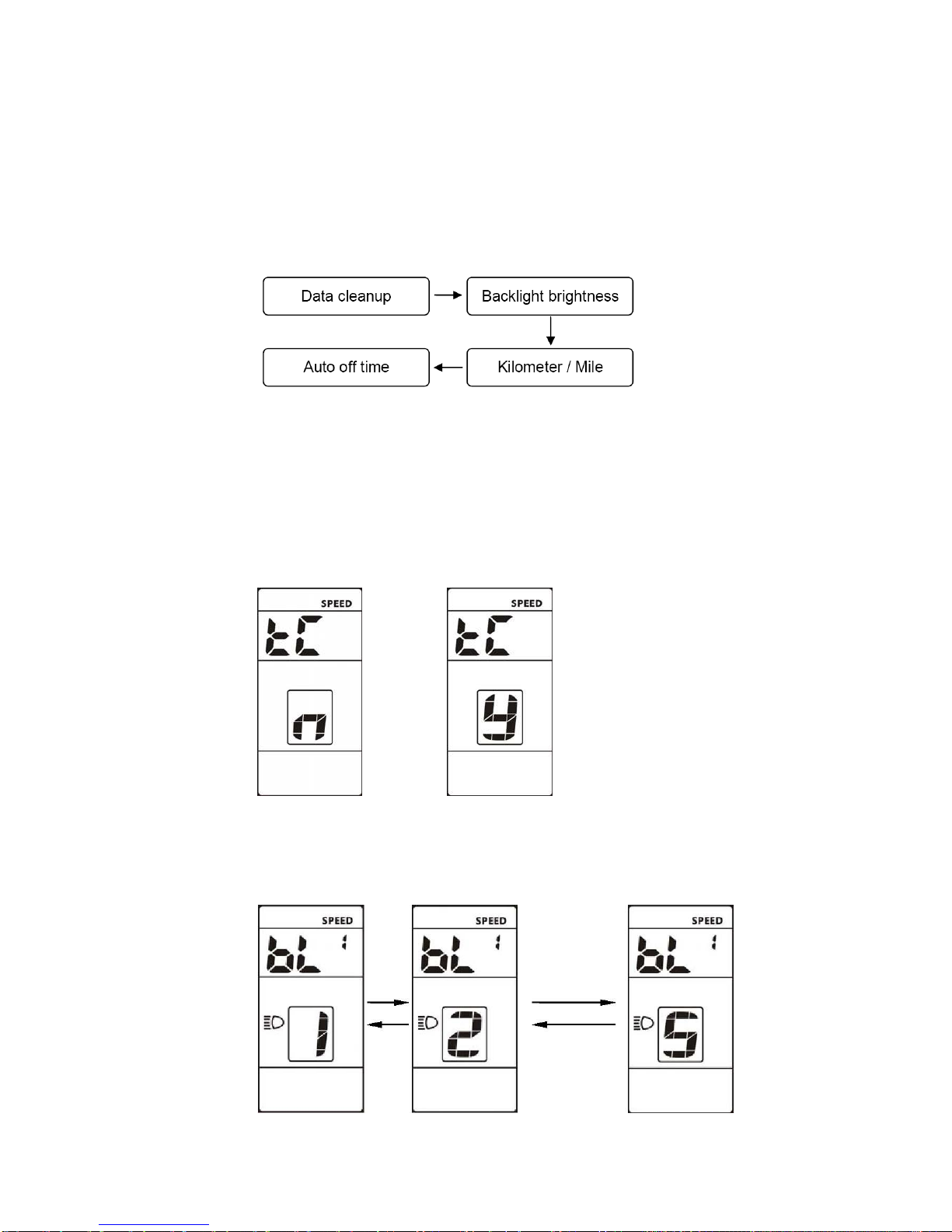
7.1 Data clean-up
Data Clean-up resets: AVG Speed, MAX Speed, Trip and Time data.
The symbol ‘tC’ is displayed. The ‘n’ and ‘y’ symbols represent ‘No’ and ‘Yes’.
To perform a ‘Data clean-up’change to ‘y’ using the UP or DOWN button and
press the POWER button. To move to the next parameter press the ‘POWER’
button while ‘n’ is displayed.
7.2 Backlight brightness
Symbol ‘bL 1’ is displayed. Press the UP or DOWN button to change the
brightness value, the range is 1 to 5. The default value is 3.

7.3 Kilometres / Miles
The symbol ‘S7’ is displayed. Press the UP or DOWN button to change
between Km (Km/h) and Mile (MPH), then press the POWER button to
confirm.
7.4 Auto off time
The symbol ‘OFF’ is displayed. Press the UP or DOWN button to change the
value, the range is 1 to 9, the number represents the delay time in minutes,
before the display shuts down automatically. The default value is 5 minutes.

8. Password Protected Menu
To get to the password protected menu you must first enter the basic menu by
pressing the ‘UP’ and ‘DOWN’ buttons simultaneously. Now repeat this to enter the
password protected menu. To use the menu you must enter a 4 digit password. The
default password is “0512”. Use the UP or DOWN buttons to change the number
and the ‘POWER’ button to confirm and move to the next number. When the last
number is entered and the password is correct, you will move to the first menu item
(Wheel diameter).
Note about the following display functions:
The display functions detailed in sections 8.5 to 8.17 may not be enabled, so
although they may appear, they will have zero values.
8.1 Password
The symbol ‘PSd’ is displayed together with “0000”. Enter the password as
described above.

8.2 Wheel diameter
The symbol ‘Wd’ is displayed. Use the UP or DOWN button to select your
wheel diameter in inches.
The range is: 8/10/12/14/16/18/20/22/24/26/27/28/29
Selecting the wrong value will cause speed and distance errors.
8.3 Speed limit
The current speed limit value is displayed; the default value is 27Km/h. Use
the UP or DOWN buttons to modify the value from 10 to 99Km/h, although the
upper speeds would probably not be achieved due to restrictions within the
motor and controller.
8.4 Range of assist level settings
The ‘PAS’ symbol is displayed. You can choose the range of power assist
levels, the default is UBE. Press the UP or DOWN buttons to change the
value to 0-3, 0-5, 0-9 or UBE. See table in section 11.

8.5 The Current temperature:
The ‘b01’ symbol is displayed together with the current temperature value.
8.6 The Maximum temperature:
The ‘b02’ symbol is displayed together with the maximum temperature value.
8.7 The lowest temperature:
The ‘b03’ symbol is displayed together with the lowest temperature value.
8.8 The total voltage:
The ‘b04’ symbol is displayed together with the total value.

8.9 Current:
The ‘b05’ symbol is displayed together with the current value.
8.10 Average current:
The ‘b06’ symbol is displayed together with the average current value.
8.11 The remaining capacity:
The ‘b07’ symbol is displayed together with the remaining capacity value.
8.12 Full charge capacity:
The ‘b08’ symbol is displayed together with the full charge capacity value.

8.13 The relative state of charge:
The ‘b09’ symbol is displayed together with the relative state of charge value.
8.14 The absolute state of charge:
The ‘b10’ symbol is displayed together with the absolute state of charge
value.
8.15 Cycle:
The ‘b11’ symbol is displayed together with the cycle value.
8.16 The maximum no charging time:
The ‘b12’ symbol is displayed together with the maximum no charge time.

8.17 No recent charging time:
The ‘b12’ symbol is displayed together with the no recent charging time.

9. Error Codes
If there is a problem with your E-bike an error code will be displayed. The engine
icon will appear with an error code ranging from 01H~FFH.
See table below for error code descriptions.
Error Code
Error description
Error display
0x01
Normal
No error
0x03
Brake signal
Display 03 on speed position
0x06
Low voltage
protection
Display 06 on speed position
0x07
High voltage
protection
Display 07 on speed position
0x08
Hall line of motor
error
Display 08 on speed position
0x09
Phase line of the
motor error
Display 09 on speed position
0x10
High temperature of
controller
Display 10 on speed position
0x11
Controller’s
temperature sensor
error
Display 11 on speed position
0x12
Current sensor error
Display 12 on speed position
0x13
Battery’s
temperature sensor
error
Display 13 on speed position
0x14
Motor‘s temperature
sensor error
Display 14 on speed position
0x21
Motor‘s speed
sensor error
Display 21 on speed position
0x22
BMS
communication
error
Display 22 on speed position
0x23
Head light error
Display 23 on speed position
0x30
Communication
error
Display 30 on speed position


10. Assembly instructions
Please pay attention to the screw’s torque value; damage caused by excessive
torque is not within the scope of the warranty.
There are 2 directions for the clamp installation, forward or backward.
Different assembly methods will need different cable length.

Clamps are suitable for 3 sizes of handlebar, 31.8mm, 25.4mm, and 22.2mm, there
are transfer rings for 25.4mm and 22.2mm. Transfer rings must be assembled in the
correct direction as illustrated by the green arrow below.
11. Assist level instructions
The range of assist levels can be selected (see section 8.4), the highest
number of levels is 9, see the table below to see how 3 and 5 levels correlate
to 9:
3 levels
5 levels
9 levels
0
0
1
1
2
1
2
3
4
3
5
2
6
4
7
8
3
5
9
12. Certification
CE / IP65 (water proof) / ROHS.
Table of contents