manuals.online logo
Brands
  1. Home
  2. •
  3. Brands
  4. •
  5. Brigit Systems
  6. •
  7. Smoke Alarm
  8. •
  9. Brigit Systems BRS-SC User manual

Brigit Systems BRS-SC User manual

BRS-SC
Non-addressable Smoke Detector, Installation Instructions
32-0033_106W
PAGE 1
While every precaution has been taken during the preparation of this document to ensure the accuracy of its content, Brigit Group
assumes no responsibility for errors or omissions. Brigit Group reserves the right to make changes to the product or this document without notice.
JHB tel: +27 11 794 2217 / CT tel: +27 21 300 1452 / DBN tel: +27 67 412 8349 / Email: sales@brigit.co.za
www.brigit.co.za
BRS-SC
Non-addressable Smoke Detector,
Installation Instructions
32-0033_106W
MANUAL
www.brigit.co.za
BRS-SC
Non-addressable Smoke Detector, Installation Instructions
32-0033_106W
PAGE 2
While every precaution has been taken during the preparation of this document to ensure the accuracy of its content, Brigit Group
assumes no responsibility for errors or omissions. Brigit Group reserves the right to make changes to the product or this document without notice.
JHB tel: +27 11 794 2217 / CT tel: +27 21 300 1452 / DBN tel: +27 67 412 8349 / Email: [email protected].za
www.brigit.co.za
Cautions
ELECTRICAL HAZARD: Disconnect power from
equipment prior to making any internal
adjustments. Service should only be performed
by qualified personnel.
FRAGILE: Inspect the equipment prior to
installation. Do not install the equipment if
damage is apparent. Do not attempt to
disassemble this equipment. If damaged, return
to the supplier.
ELECTROSTATIC HAZARD: This is sensitive
electronic equipment. Apply safe ant-static
practices when handling this equipment.
CIRCUIT LIMITATIONS: The maximum number of
detectors connected to a single detection zone is
limited by the control and indicating equipment,
and may be limited by local regulations.
Preparation
Before commencing installation, ensure all equipment
(base and detector) and tools to mount and connect the
equipment are available, such as drills, mounting screws,
cables and ladders.
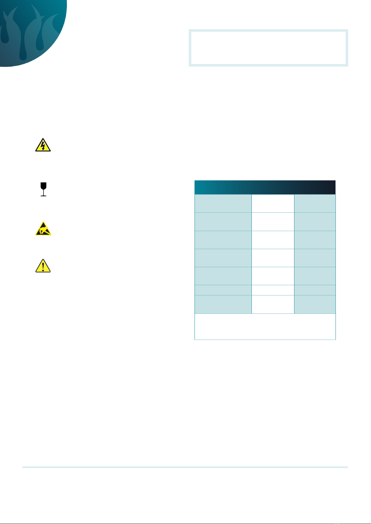
BRS-SC smoke detectors can be installed with the
following bases and accessories.
Installation
Base
The base can be mounted directly onto an electrical
junction box such as an octagonal (75 mm, 90 mm or 100
mm), a round (75 mm), or a square (100 mm) box without
using any type of mechanical adapter.
1. Feed the conductors through the middle of the base
for termination to the base contacts.
2. Mount the base on the junction box or directly onto a
flat surface.
3. Mount the base to the surface using fixing screws that
are suitable to securely fix the base to the surface.
Introduction
BRS-SC non-addressable photoelectric smoke detectors
are state-of-the-art detectors suitable for connection to
2-wire or 4-wire non-addressable fire detection control
and indicating equipment, or to addressable fire detection
control and indicating equipment that can accept non-
addressable type detectors.
These instructions provide trained installation personnel
with details to install and commission BRS-SC smoke
detectors for optimum performance.
DESCRIPTION PART NUMBER DATASHEET
5-terminal 102 mm
low profile base BRS-BC-2 31-0035
5-terminal 102 mm
low profile base aBRS-BC-2-9 31-0035
9-terminal 102 mm
low profile base BRS-BC-L 31-0037
9-terminal 102 mm
low profile base aBRS-BC-L-9 31-0037
Detector monitor
module BRS-DMM 31-0027
Remote indicator bBRS-REM 31-0034
484 relay output
base c
BRS-ROB-01
BRS-ROB-02 31-0083
aUL-approved
bRequires 9-terminal base.
cCompatible with SNC-300-SRR
 May be used with the BRS-DMM detector monitor module.
BRS-SC
Non-addressable Smoke Detector, Installation Instructions
32-0033_106W
PAGE 3
While every precaution has been taken during the preparation of this document to ensure the accuracy of its content, Brigit Group
assumes no responsibility for errors or omissions. Brigit Group reserves the right to make changes to the product or this document without notice.
JHB tel: +27 11 794 2217 / CT tel: +27 21 300 1452 / DBN tel: +27 67 412 8349 / Email: [email protected].za
www.brigit.co.za
Wiring
Base terminals accept (0.4 ~ 2.5) mm2 conductors.
1. Strip the conductor insulation to expose 5 mm of
the conductor.
2. Connect the conductors to the base terminals.
a. See Fig. 1 for detectors using 2-wire bases.
b. See Fig. 2 for detectors using 4-wire bases.
WARNING: Take care to ensure the insulation does
not get clamped by the terminal contact.
Fig. 1: 2-wire base wiring connections
Note 1: 9-terminal base required if a remote indicator is
installed.
Note 2: If a remote indicator is not installed, the polarity of
the zone circuit wiring may be reversed.
WARNING: Do not short-circuit terminals 2 and 5.
Fig. 2: 4-wire base wiring connections
3. After all the bases are installed and wired, fit the end-
of-line resistor.
Note: The value of the end-of-line resistor depends on the
control and indicating equipment to which the detectors
are installed.
4. Check the wiring for continuity, short circuits and
earth faults.
Detector
WARNING: Do not install the detector head until
the area is thoroughly cleaned of construction
debris, dust, etc.
1. Align the detector alignment mark with the short
alignment mark in the base, as shown in Fig. 3.
2. Mate the detector head onto the base and rotate it
clockwise to secure it. The long alignment marks
should be aligned.
Fig. 3: Fitting the detector to the base
Commissioning
Smoke Detector
1. Ensure all the alarm signal services, releasing devices
and extinguisher systems are disabled during the
commissioning period.
2. Connect power to the detector for approximately 1
min and check that the red alarm LED indicators flash
once every 3 s. If the LED fails to flash, it indicates
the detector is not operating. Check the wiring for
the correct voltage and earth leakage. Replace the
detector if necessary.
3. Allow smoke from a cotton wick or a test smoke
aerosol to enter the detector-sensing chamber for
at least 10 s. When sufficient smoke has entered
the chamber, the detector will signal an alarm, by
continuous illumination of the LED.
Output Relay (where fitted)
The output relay is factory-adjusted with normally-open
contacts that close on alarm. No setting adjustment is
required.
BRS-SC
Non-addressable Smoke Detector, Installation Instructions
32-0033_106W
PAGE 4
While every precaution has been taken during the preparation of this document to ensure the accuracy of its content, Brigit Group
assumes no responsibility for errors or omissions. Brigit Group reserves the right to make changes to the product or this document without notice.
JHB tel: +27 11 794 2217 / CT tel: +27 21 300 1452 / DBN tel: +27 67 412 8349 / Email: [email protected].za
www.brigit.co.za
4. Upon alarm, immediately remove the smoke source.
5. Check that the detector LEDs are off and the control
and indicating returns to the quiescent condition.
References
Document : 31-0045
Description : BRS-SC non-addressable smoke detector
datasheet
View the complete range of products at
www.brigit.co.za
Remote Indicator (where fitted)
Check that the indicator illuminates at the same time as
the detector LEDs.
Output Relay (where fitted)
1. Follow Smoke Detector procedure steps 3 ~ 4.
2. Monitor the output relay for activation.
3. Reset the detector from the control and indicating
equipment.
4. Monitor the output relay for reset to its quiescent
setting.
Auto-Reset (where fitted)
1. Follow Smoke Detector procedure steps 3 ~ 4.
2. Monitor that the detector automatically resets.
The auto-reset will typically reset the detector within 30 s
of the removal of the smoke source.
Final Conditions
Ensure all the alarm signal services, releasing devices and
extinguisher systems disabled for the commissioning are
returned to their previous condition.

Popular Smoke Alarm manuals by other brands

First Alert SA300 user manual

First Alert

First Alert SA300 user manual

American Sensor SA308 manual 

American Sensor

American Sensor SA308 manual 

Quell Q307 manual

Quell

Quell Q307 manual

Xtralis VESDA VLC Product guide

Xtralis

Xtralis VESDA VLC Product guide

Alecto SA-200 manual

Alecto

Alecto SA-200 manual

H+H RM 04 operating instructions

H+H

H+H RM 04 operating instructions

Smoke hollow SH36GW Assembly & operation

Smoke hollow

Smoke hollow SH36GW Assembly & operation

Notifier NFX-OPT Installation and maintenance instructions

Notifier

Notifier NFX-OPT Installation and maintenance instructions

Metasys 2551J manual

Metasys

Metasys 2551J manual

System Sensor OSI-RE-SS Installation and maintenance instructions

System Sensor

System Sensor OSI-RE-SS Installation and maintenance instructions

Bosch RFSM-A installation guide

Bosch

Bosch RFSM-A installation guide

Siterwell GS511-B-H01 user manual

Siterwell

Siterwell GS511-B-H01 user manual

Aico Ei169RF Specification sheet

Aico

Aico Ei169RF Specification sheet

detectomat HDv 300 OS Series Operation and installation manual

detectomat

detectomat HDv 300 OS Series Operation and installation manual

Fire-Lite Alarms 1400 quick start guide

Fire-Lite Alarms

Fire-Lite Alarms 1400 quick start guide

SPECAVTOMATIKA DOKA Instruction

SPECAVTOMATIKA

SPECAVTOMATIKA DOKA Instruction

Kidde KN-COSM-BA user manual

Kidde

Kidde KN-COSM-BA user manual

Bosch FAS-420-TM Quick installation guide

Bosch

Bosch FAS-420-TM Quick installation guide

manuals.online logo
manuals.online logoBrands
  • About & Mission
  • Contact us
  • Privacy Policy
  • Terms and Conditions

Copyright 2025 Manuals.Online. All Rights Reserved.