Brink Air 70 User manual

Air 70 (Plus)
WWW.BRINKAIRFORLIFE.NL 614397-D
INSTALLATION INSTRUCTIONS (English)


Heat recovery appliance
Air 70 (Plus)
STORE NEAR THE APPLIANCE
Installation instructions
This appliance may be used by children aged 8 and above, persons with reduced mental capacity, physical limita-
tions or lack of experience and knowledge, provided they are under supervision or have received instructions on
how to use the appliance safely and are aware of the potential hazards.
Children are not allowed to play with the appliance.
Without supervision, cleaning and user maintenance must not be performed by children, persons with reduced
mental capacity, physical limitations or lack of experience and knowledge.
GB

Air 70 Rev. D
Table of contents
1
1.1
1.2
2
3
3.1
3.2
3.3
4
4.1
4.2
4.3
4.4
5
5.1
5.2
5.3
5.4
5.5
5.5.1
5.5.2
5.5.3
5.5.4
5.5.5
6
6.1
6.2
6.3
6.4
6.5
7
7.1
8
8.1
8.2
9
9.1
9.2
10
10.1
10.2
10.3
10.3.1
10.3.2
10.4
10.5
10.6
10.7
10.8
11
11.1
12
12.1
13
13.1
Delivery......................................................................................................................................................................
Scope of delivery........................................................................................................................................................
Accessories Air 70......................................................................................................................................................
Application................................................................................................................................................................
Version.......................................................................................................................................................................
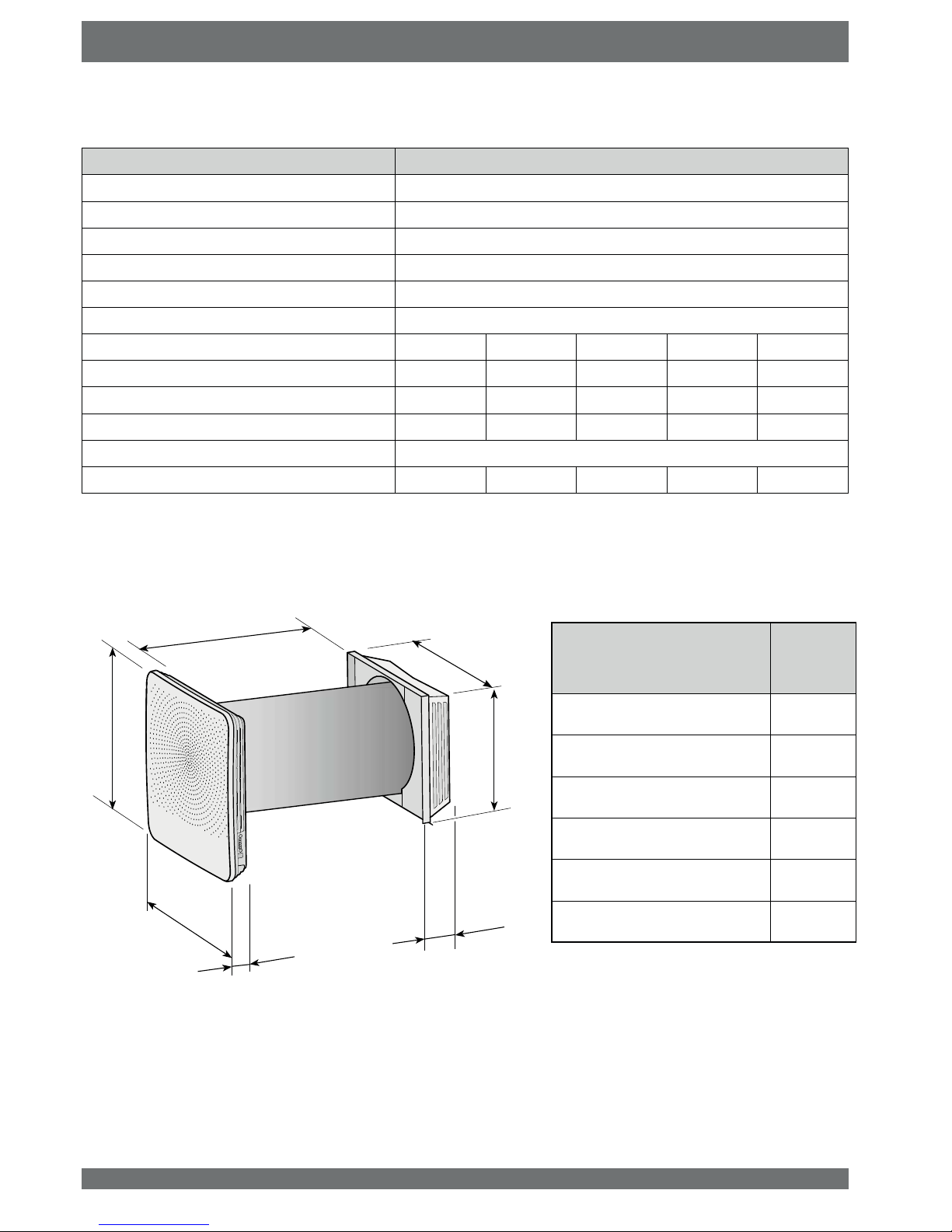
Technical information..................................................................................................................................................
Dimensions.................................................................................................................................................................
Exploded view appliance............................................................................................................................................
Operation...................................................................................................................................................................
Description..................................................................................................................................................................
Bypass conditions.......................................................................................................................................................
Frost safety.................................................................................................................................................................
Air 70 Plus version......................................................................................................................................................
Installation.................................................................................................................................................................
Installation general .....................................................................................................................................................
Placing the appliance .................................................................................................................................................
Painting output grill front cover...................................................................................................................................
Installation sequence..................................................................................................................................................
Electric connections....................................................................................................................................................
Connecting the power plug.........................................................................................................................................
Connecting the optional multiple switch (only for Plus version)..................................................................................
Connection eBus connector (only for Plus version)....................................................................................................
Connection optional On/Off switch.............................................................................................................................
Connection MODBUS connector (only for Plus version)............................................................................................
Putting into operation..............................................................................................................................................
Powering the or taking the voltage from the appliance...............................................................................................
Switching the appliance on and off.............................................................................................................................
6HWWLQJWKHDLUÀRZUDWH................................................................................................................................................
Reset factory settings.................................................................................................................................................
Other settings installer................................................................................................................................................
Fault...........................................................................................................................................................................
Trouble shooting.........................................................................................................................................................
Maintenance..............................................................................................................................................................
&OHDQLQJ¿OWHUV............................................................................................................................................................
Installer maintenance .................................................................................................................................................
Electric circuit...........................................................................................................................................................
Wiring diagram Basic pcb...........................................................................................................................................
Wiring diagram Plus pcb.............................................................................................................................................
Electric connections accessories...........................................................................................................................
Mounting Plus pcb......................................................................................................................................................
Connecting RH (humidity) sensor (only possible for Plus pcb) ..................................................................................
Connection examples multiple switch.........................................................................................................................
0XOWLSOHVZLWFKZLWK¿OWHULQGLFDWLRQ.............................................................................................................................
:LUHOHVVUHPRWHFRQWUROZLWKRXW¿OWHULQGLFDWLRQ.......................................................................................................
Connecting CO
2
sensor (only possible for Plus pcb)..................................................................................................
Connecting external switch (only possible for Plus pcb) ............................................................................................
Connecting Brink Home i module (only possible for Plus pcb)...................................................................................
Connecting Air 70 on MODBUS (only possible for Plus pcb).....................................................................................
Linking appliances through eBus (only possible for Plus pcb) ...................................................................................
Incident setting.........................................................................................................................................................
Shutting off air supply an exhaust in case of incidents...............................................................................................
Service ......................................................................................................................................................................
Exploded view ............................................................................................................................................................
Setting values...........................................................................................................................................................
Setting values when using the Brink service tool .......................................................................................................
Declaration of conformity........................................................................................................................................
ErP-values.................................................................................................................................................................
1
1
2
3
4
4
4
5
6
6
6
6
6
7
7
7
7
8
13
13
13
13
14
14
15
15
15
16
16
16
17
17
19
19
20
25
25
25
26
26
26
26
27
27
28
28
29
29
30
31
310
32
32
33
33
34
35

Air 70 Rev. D 1
Chapter 1 Delivery
1.1 Scope of delivery
Before starting installation of the heat recovery appliance, check that it has been supplied in complete and undamaged condition.
The scope of delivery of the decentral heat recovery appliance typeAir 70 comprises two assemblies ( 1 - 6) ; the version of assembly
7a - 7f depends on the wall thickness.
The two assemblies consist of the following components:
1 Front cover
2 Interior section Air 70
3 Exchanger/fan combination Air 70
4 Wall sleeve
5 Calamities cap (folded, stowed in appliance)
6 Concise manual + mounting hardware
D ([WHULRUVHFWLRQ$LUIRUZDOOWKLFNQHVVPP¿QLVK66RUZKLWH
or
7b ([WHULRUVHFWLRQ$LUZLWKH[WHQVLRQNLWIRUZDOOWKLFNQHVVPP¿QLVK66RUZKLWH
or
7c ([WHULRUVHFWLRQ$LUZLWKH[WHQVLRQNLWIRUZDOOWKLFNQHVVPP¿QLVK66RUZKLWH
or
7d Exterior section Air 70 with extension kit for wall thickness 350-400 mm;
¿QLVK66RUZKLWH
or
7e Exterior section Air 70 with extension kit for wall thickness 300-350 mm;
¿QLVK66RUZKLWH
or
7f Exterior section Air 70 with extension kit for wall thickness 270-300 mm;
¿QLVK66RUZKLWH
4
6
3
2
1
5
7a
7b
7c
7d
7e
7f
218
168
118
68
85
248

2 Air 70 Rev. D
Chapter 1 Delivery
1.2 Accessories
Article description Article code
Plus-pcb 450104
CO2sensor 450101
RH (humidity) sensor 450102
Brink home i module 450103
On/Off switch (internal) 450105
Filter kit F7 (2x G4/ 1 x F7) 450109
ZD\VZLWFKZLWK¿OWHULQGLFDWLRQ 540262
Transmitter wireless remote control 2 positions (with battery) 532170
Transmitter wireless remote control 4 positions (with battery) 532171
Receiver wireless remote control (for battery version) 532172
Kit wireless remote control 2 positions (1 transmitter & 1 receiver) 52173
Kit wireless remote control 4 positions (1 transmitter & 1 receiver) 532174
Brink service tool 531961

Air 70 Rev. D 3
The BrinkAir 70 is a decentral heat recovery ventilation unit for
application in an exterior wall. The maximum ventilation capac-
ity of the appliance is 70 m
3
/h.
Features Air 70:
DLUTXDQWLW\DGMXVWDEOHXVLQJFRQWUROEXWWRQV
¿OWHULQGLFDWLRQRQWKHDSSOLDQFH
DIURVWSURWHFWLRQV\VWHPWKDWDOVRDWORZRXWGRRUWHPSHUD-
tures ensures that the appliance's performance remains op-
timal and, if necessary, activates the standard preheater
ORZVRXQGOHYHO
FRPHVDVVWDQGDUGZLWKDXWRPDWLFE\SDVVYDOYH
ORZHQHUJ\FRQVXPSWLRQ
KLJKHI¿FLHQF\
The performance and the energy consumption of the Air 70
GHSHQGRQWKHDLUTXDQWLW\VHWWLQJDVZHOODVRQWKH¿OWHUIRXOLQJ
The Air 70 is available in two types:
³$LU´
³$LU´
Compared to the standard Air 70, the Air 70 Plus has a more
advanced control pcb with additional connection options for,
among others, RH (humidity) sensor, CO
2
-sensor, multiple
switch or Brink Home i module.
These installation instructions describe both the standard Air
70 and the Air 70 Plus.
Please state the correct type when ordering an appliance.
For dimensions, see §3.2.
TheAir 70 comes ready to plug in with a 230 V mains plug and
a connection for the Brink service tool on the outside of the
appliance.
The appliance comes with an emergency cap. In the event of
an emergency for which the air supply and exhaust to the at-
mosphere must be shut off, the emergency cap must be placed.
7KLVFDSLVVWRUHGLQWKHDSSOLDQFH%HIRUHSODFLQJWKHFDS¿UVW
the appliance must be switched off (pull the mains plug or, if
installed, put the On/Off switch to 0).
See §11.1 for more detailed information.
Always remove this calamity cap before switching the
appliance back on!
Chapter 2 Application
Warning
The preheater and the Control pcb carry 230 V. Always take the voltage from the appliance
by pulling the mains plug when working on the appliance.

4 Air 70 Rev. D
Chapter 3 Version
3.1 Technical information
Air 70
Supply voltage [V/Hz] 230/50
Protection degree Interior section IP20/ Exterior cover IPX4
Dimensions (w x h x d) [mm] See 3.2
Duct diameter through the wall [mm] Ø250
Weight [kg] 12 (13.5 with exterior cover)
Filter class 2 x G4 (exhaust) & 1x G4 (supply)
Fan setting (factory setting) 1 2 3 4 5
Ventilation capacity [m
3
/h] 1525405570
Rated power [W] 4.2 5.3 8.0 14.0 23.5
Rated current [A] 0.05 0.07 0,10 0.15 0.23
Max. rated current [A] 1,3
&RVij 0.34 0.34 0.36 0.40 0.45
3.2 Dimensions
65
398
398
355
315
Extension kit 7a - 7f
(for explanation kits see § 1.1) Size Q
[mm]
7a (Wall thickness 500-600 mm) 85
7b (Wall thickness 450-500 mm) 135
7c (Wall thickness 400-450 mm) 185
7d (Wall thickness 350-400 mm) 235
7e (Wall thickness 300-350 mm) 285
7f (Wall thickness 270-300 mm) 315
600 mm
Q

Air 70 Rev. D 5
Chapter 3 Version
1 Front cover
2([KDXVWDLU¿OWHU*XQLWV
3,QGRRUWHPSHUDWXUHVHQVRU
46XSSO\DLU¿OWHU*XQLW
5 Bypass motor
6 Bypass with mounted bypass slide
7 Heat exchanger
8 EPP housing (2 parts)
9 Outdoor temperature sensor
10 PVC Wall sleeve Ø250 mm
11 Mounting plate exterior cover
12 Exterior cover
3.3 Exploded view appliance
13 Maximum safety preheater
14 Preheater
15 Fan
16 Internal condensate discharge
17 &RQWURO EXWWRQV USP FRQWURO ¿OWHUUHVHW VZLWFKLQJ WKH
appliance on and off
18 Service connector
19 LEDs (5x)
20 &RQWUROSFE
21 Mains plug 230 V.
22 3OXVSFERSWLRQ
23 2SWLRQDO2Q2IIVZLWFK
* These parts are not visible in the picture
23
156 7 810 11 12 13
14
15
17
18
4
23 19 16
20
21
22
9

6 Air 70 Rev. D
The Air 70 is also available as "Plus" version. This version
features a second control pcb with additional connectors (X8
- X19) with more connection options for several applications.
See § 9.2 for more information about the connection options of
the Plus pcb connectors X8 - X15.
The “Plus” print connector is "clicked" directly on the control
pcb.
7KHDSSOLDQFHZLWKRQO\DEDVLFSFEFDQDOVREHDGMXVWHGDIWHU-
wards in a simple manner to a Plus version
Just like the Control pcb connectors, the Plus connectors are
accessible after the front cover has been removed (see §8.1
item 2); then the cover that protects the electronics can be un-
screwed (see §5.4 item 6).
One breakout tab is available at the rear for connecting the plus
pcb with components outside the appliance.
The Plus pcb must always be "signed on" to the Con-
trol pcb, DIP switch 1 must be ON (see §10.1)
Chapter 4 Operation
4.3 Frost safety
To prevent freezing of the heat exchanger at extremely low
outdoor temperatures, the Air 70 features intelligent frost con-
trol. The built-in preheater is activated when the outdoor tem-
perature drops below -1.5°C. That guarantees proper balanced
ventilation at all times.
Only when the outdoor temperature drops so low that the pre-
KHDWHU FDSDFLW\ LV LQVXI¿FLHQW WKH YHQWLODWLRQ FDSDFLW\ LV UH-
duced to protect the exchanger from freezing over.
4.4 Air 70 Plus version.
4.1 Description
The appliance comes plug and play and operates fully auto-
matically. The exhaust air from indoors heats up the fresh,
clean outdoor air. That saves energy while fresh air is supplied
to the dwelling.
7KHFRQWUROV\VWHPKDV¿YHSUHSURJUDPPHGYHQWLODWLRQPRGHV
4.2 Bypass conditions
The appliance features a bypass function. The bypass is in-
tended to lead the cooler outdoor air around the exchanger
during the night after a hot summer's day. That way the cooler
outdoor air directly enters the dwelling. The bypass motor ac-
tivates the bypass slide when the bypass conditions are satis-
¿HG7KHQWKHUHLVRQO\DPHFKDQLFDOH[KDXVWDLUÀRZWKURXJK
the heat exchanger, so that under these conditions -undesired-
heat recovery does not occur.
Bypass conditions
Bypass open - The outdoor temperature is higher than 16°C and
- the outdoor temperature is lower than the indoor temperature in the dwelling and
- the temperature in the dwelling is higher than the bypass temperature (standard setting 22°C)
Bypass closed - The outdoor temperature is lower than 160°C or
- the outdoor temperature is higher than de indoor temperature in the dwelling or
- the temperature from the dwelling is lower than the bypass temperature minus the set hysteresis
temperature; the factory setting for this temperature is 20°C (22.0°C minus 2.0°C).

Air 70 Rev. D 7
Chapter 5 Installation
5.1 Installation general
Installing the appliance
1. Setting up the appliance (§5.2 and §5.4)
2. Electric connection (§5.5)
Connecting the mains power and, if necessary, the eBus
connection
Installation must take place in compliance with:
4XDOLW\UHTXLUHPHQWVYHQWLODWLRQV\VWHPVGZHOOLQJV
4XDOLW\UHTXLUHPHQWVEDODQFHYHQWLODWLRQGZHOOLQJV
5HJXODWLRQVIRUYHQWLODWLRQRIGZHOOLQJVDQGUHVLGHQWLDO EXLOG-
ings
6DIHW\SURYLVLRQVIRUORZYROWDJHLQVWDOODWLRQV
$Q\DGGLWLRQDOUHJXODWLRQVRIWKHORFDOSRZHUFRPSDQLHV
7KH$LULQVWDOODWLRQLQVWUXFWLRQV
5.2 Setting up the appliance
The Air 70 can directly be mounted using the screws supplied
for that purpose.
In addition, the following must be observed.
7KHDSSOLDQFHPXVWEHPRXQWHGDWDSLWFKRIWRZDUGV
the outside.
7KHLQVWDOODWLRQURRPPXVWEHIURVWIUHH
7KHLQWHULRUDQGH[WHULRUFRYHUVPXVWEHOHYHO
7KHDSSOLDQFHPXVWEHFXWWRWKHFRUUHFWOHQJWKWRPDWFKWKH
wall thickness.
7RDOORZ¿OWHUFOHDQLQJDQGPDLQWHQDQFHDIUHHVSDFHPXVW
be provided of at least 70 cm at the front of the appliance
and a free headroom of 1.8 m.
'RQRWSODFHWKHDSSOLDQFHDERYHDZLQGRZRUGRRUEHFDXVH
droplets or icicles may form at the underside of the outdoor
cover.
5.3 Painting outlet grill front cover
If required, the outlet grill of the front cover can be painted in
a different colour. Standard colour is RAL 9003. The synthetic
outlet grille is made of PC/ABS; Consult your paint supplier for
the use of the correct type of paint.
Make sure that all holes of the outlet grill remain open!
Unscrew 8 screws on the inside to remove the outlet cover;
then the outlet grille can be removed from the front cover.
Outlet grille
8x) Torx T10
«
= Clean outdoor air into the dwelling
= Exhaust "foul" indoor air to atmosphere
A = Minimum height > 800 mm
B = Spacing > 100 mm
C = Spacing > 300 mm
D = Free space for appliance> 750 mm
«
«
«
A
B
C
C
D
B
B
C
C

8 Air 70 Rev. D
Chapter 5 Installation
There are two ways required the hole for mounting appli-
ance can be drilled in the wall, namely:
A hole with a diameter of Ø280 mm at right angles
through the wall,
A hole with a diameter of Ø260 mm at an angle of 3 °.
WALL THICKNESS BETWEEN 500 MM AND 600 MM
(with wall thickness between 300 mm and 500 mm go to
point 3)
Ø280 mm
2b
3°
Y
5.4 Installation sequence
90°
Cut wall sleeve at length X.
X = Y + 34 mm
Example
Wall thickness = 535 mm
Cut length = 535 + 34 = 569 mm
x
90°
Before you start drilling verify the presence of pipes
in the wall!
Ø260 mm
93°
Be careful when drilling to prevent the hole in the
inner wall to prevent outbreak of pieces from wall /
plaster!
Hole of Ø280 mm drilling at right angle
Hole of Ø260 mm at a angle of 3°
1
2
2a
MOUNTING WALL SLEEVE AND EXTERIOR COVER
DRILL HOLE IN WALL
Wedges
(These are not required if the hole in the
wall has already been drilled at a pitch!)
Wall sleeve to be
sealed all around
using moisture-
resistant sealant.
Ø
260 mm
Y
Exterior
wall
Ø
280 mm
Y
Exterior
wall
Align the wall sleeve with separating wall.
separating wall
wall sleeve
Aligning here!
Locate wall sleeve at top
of drilled hole!
Exterior wall
Separating
wall
0 mm

Air 70 Rev. D 9
Chapter 5 Installation
2c
2d
2e
4x) 5 x 60 mm
hook up
1x Torx T15
Cut wall sleeve at length X
X = Y + imensions extension kit + 16 mm
Refer to §1.1 for the dimensions of the extension kit.
Example
Wall thickness = 420 mm
Cut length = 420 + 118 + 16 = 554 mm
90°
x
WALL THICKNESS BETWEEN 300 MM AND 500 MM
3
Y
3b
3a
4x
3°
Cable
Wedges
(These are not required if the hole in the wall has
already been drilled at a pitch!)
Wall sleeve to
be sealed all
around using
moisture-resist-
ant sealant.
Align the wall sleeve with separating wall.
Separating wall
wall sleeve
Aligning here!
Locate wall sleeve at top of
drilled hole!
Exterior wall
Separating
wall
0 mm

10 Air 70 Rev. D
Chapter 5 Installation
Torx T15
2x
hook up
3c
3j
3k
2x
3h
3d
4x) 5 x 40 mm
3e
3f
3g
3i A
B
C
>
Center relative to
wall sleeve! Torx T15
1x
1x Torx T15
Lead the
cable through
wall sleeve!
A
B

Air 70 Rev. D 11
Chapter 5 Installation
4
8
5
9
7
Only drill these holes for a
permanent mains supply; see §5.5.4
6
2x Torx T15
2x Torx T15
4x) 3,5x38mm
Template
(On packaging
interior part)
Align template with
top of drilled hole!
MOUNTING INDOOR UNIT
Make sure that also the ground wire of the pre-
heater is mounted on terminal X1 (see also §9.1)
Cable X2
1
2
2
1
Place cable to exterior cover neatly in
the special groove!

12 Air 70 Rev. D
Chapter 5 Installation
15
14
16
17
For electric connections of the appliance, see §5.5.
After making the electric connections to the appliance, it
can be put into operation; see §6.1
13
10
Z
¨
Z
12
11
TOP
Z
TOP
90°
Z
1
2
°
¯
wall sleeve
bottom cam
Z = max. 100 mm
IRUVL]H=VHH¿JXUH
X5

Air 70 Rev. D 13
An optional 4-way switch is connected to the modular connec-
tor type RJ12; connection X13 to plus pcb. This connector is
accessible after removing the front cover (see respectively
§8.1 item 2).
If a 4-way switch is connected, the settings according to the
table below will be linked to the ventilation modes of the Air
70. The current ventilation mode can only be changed with the
push buttons on the appliance when the switch is on setting 1.
7KH$LUXVHVWKHH%XVSURWRFRO7KH3OXVSFELV¿WWHGZLWK
two 2-pole (detachable) screw connectors X14 and X15 for
making the eBus connection.
The eBus protocol may for instance be used to link (cascade
control) appliances (see §10.8). Because of polarity sensitiv-
ity, always connect contacts X1-1 to X1-1 and contacts X1-2
to X1-2; the appliance will not work when these contacts are
interchanged.
Control pcb
Plus pcb
Control pcb
Plus pcb
eBus connector X14/
X15 on Plus pcb
modular connector X13
on Plus pcb
Chapter 5 Installation
Warning
The preheater and the Control pcb carry 230 V.
Always take the voltage from the appliance by
pulling the mains plug when working on the ap-
pliance.
5.5 Electric connections
5.5.3 Connecting the eBus connector (only possible for Plus version)
5.5.2 Connecting the optional multiple switch (only possible for Plus version)
5.5.1 Connecting the power plug
The appliance can be connected to an easily accessible,
earthed wall socket with the plug that is mounted to the ap-
pliance. The electric installation must comply with the require-
ments of your power company.
Make allowance for the 175 W preheater.
Refer to diagrams §10.3.1 to §10.3.2 for connection examples
multiple switch.
Position
4-way switch Ventilation mode Air 70
1
1
23
35
* Setting 1 of the 4-way switch is a non-switched setting (cur-
rent ventilation mode = setting as per appliance).

14 Air 70 Rev. D
5.5.4 Connecting optional On/Off switch
If the Air 70 is connected to a permanent 230 V power source,
the appliance - both the basic and the Plus versions - must be
equipped with the optionally available two-pole On/Off switch.
It can be placed in the appliance on the left-hand side; a break-
out opening for this switch is provided.
At the location of this permanent power supply, a hole must be
PDGHLQWKHZDOOEHKLQGWKHDSSOLDQFHIRUDMXQFWLRQER[7KH
H[DFW ORFDWLRQ RI WKH MXQFWLRQ ER[ LV LQGLFDWHG RQ WKH GULOOLQJ
template used to drill the holes from inside the unit (see §5.4
item 4).
Refer to the installation instructions that come with this switch
for the electric connection of this On/Off switch.
Control pcb
Breakout opening
switches
Position junction box
230 V
Chapter 5 Installation
5.5.5 Connecting MODBUS connector (only possible for Plus version)
The Air 70 supports the MODBUS protocol.
A 3-pole (detachable) screw terminal X11 is available on the
plus pcb for connecting a MODBUS link. MODBUS can be
used to connect the appliance to a building automation system.
MODBUS connector
X11 on Plus pcb
Control pcb
Plus pcb

Air 70 Rev. D 15
Chapter 6 Putting into operation
Powering the
appliance
Taking the voltage
from the appliance
6.1
Powering the or taking the voltage from the appliance
- Connect the appliance to, or disconnect it from, the mains power by inserting or pulling the mains plug or, if the optional mains
switch is installed, by setting this switch to 1 or 0 respectively.
As soon as the power is turned on or if the appliance is reset to factory settings, a self-test will be performed. During this self-test,
all LEDs are blinking green simultaneously. Operating the appliance is not possible during the self-test. The self-test takes at least
4 and no more than 9 minutes. If a fault is detected during the self-test, a fault message with blinking red LEDs will appear directly
after the self-test (see §7.1).
0
1
¨
¨
10 s.
or
Switching off the appliance for 30 minutes Switching on the appliance within 30 minutes
0
1
¨
¨
or
Green LEDs of set ventilation
mode light up during 10 sec-
onds and then they go out.
Green LEDs of set ventila-
tion mode blink Fast
+
-
+
-
>5s.
Option
Option
- Switching on and off with push buttons on the appliance.
6.2 Switching the appliance on and off
+
-
+
-
+
-
>5s.
Switching off Switching on
Green LEDs of set ventila-
tion mode blink Slow
>10s.
>10s.
+
-
+
-
10 s.
+
-
+
-
+
-
Green LEDs of set ventilation
mode light up during 10 sec-
onds and then they go out.

16 Air 70 Rev. D
Chapter 6 Putting into operation
Green LEDs
INCREASE
$,548$17,7<
6.3 Setting the air quantity
Ex factory, the air quantity of the Air 70 is set at 25 m
3
/h. With
the aid of two push buttons, the air quantity can be set to
15 m
3
/h, 25 m
3
/h, 40 m
3
/h, 55 m
3
/h or 70 m
3
/h respectively.
Green LEDs indicate the ventilation mode for a short period
after operating the buttons; 10 seconds later these LEDs go
out again.
6.4 Reset factory settings
Holding down the two push buttons for at least 15 seconds will
reset the appliance to the factory settings.As soon as the push
buttons are released, all three LEDs will simultaneously blink
green 3x successively. All changed settings have now been re-
set to the initial values that the Air 70 came with ex factory. All
VWRUHGIDXOWPHVVDJHV KDYH EHHQ GHOHWHGDQGWKH ¿OWHU PHV-
sage has also been reset.
>10 s.
>
15 m3/h 25 m3/h 55 m3/h 70 m3/h40 m3/h
6.5 Other settings installer
9DULRXVRWKHUVHWWLQJVRIWKH$LUFDQDOVREHPRGL¿HG7KLV
requires use of the Brink service tool. An overview of settings
WREHPRGL¿HGFDQEHIRXQGLQ
Please refer to the manual that comes with the Brink service
tool for more detailed information and methods for modifying
these other Air 70 settings
Press the "+" button
and "-" button simul-
taneously 15 s.
+
-
+
-
3x
+
-
+
-
+
-
+
-
+
-
+
-
+
-
+
-
DECREASE
$,548$17,7<
This manual suits for next models
1
Table of contents
Other Brink Test Equipment manuals