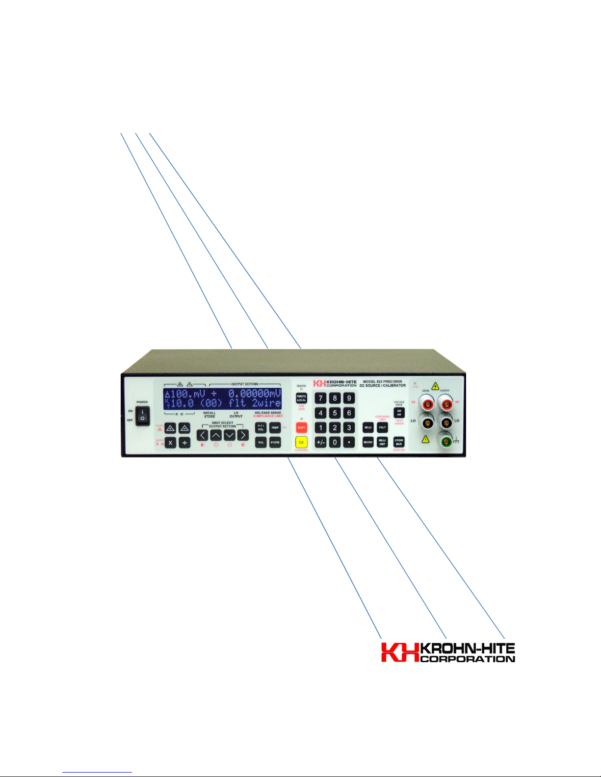
Model 523 DC Source/Calibrator
_________________________________________________________________________________
[iii]
2.2.2
Tone Annunciator ...................................................................................................................................... 11
2.2.3
Leading and Trailing Zeros ......................................................................................................................... 11
2.2.4
>15 Volt Indicator ...................................................................................................................................... 12
2.2.5
Shift Ke ..................................................................................................................................................... 12
2.2.6
Remote/Local Ke ...................................................................................................................................... 12
2.2.7
Clear Entr Ke ........................................................................................................................................... 13
2.2.8
Setting the GPIB Address ........................................................................................................................... 13
2.2.9
Crowbar Ke .............................................................................................................................................. 14
2.2.10
Voltage Ke ................................................................................................................................................ 14
2.2.11
Current Ke ................................................................................................................................................ 15
2.2.12
Compliance Limits ...................................................................................................................................... 16
2.2.13
2-Wire/4-Wire Ke (Output Termination) ................................................................................................. 17
2.2.14
Lo To Chassis Ke (flt/chs) ......................................................................................................................... 17
2.2.15
Delta Ke (ENTER ∆ ) .................................................................................................................................. 17
2.2.16
Multipl /Divide Ke (ENTER × ÷) ............................................................................................................... 18
2.2.17
+/– Polarit Ke ......................................................................................................................................... 19
2.2.18
Store/Recall Ke ......................................................................................................................................... 19
2.2.19
Temp Ke ................................................................................................................................................... 20
2.2.20
CAL Ke ...................................................................................................................................................... 20
2.2.21
Clear Mem Ke ........................................................................................................................................... 21
2.2.22
Serial No. ................................................................................................................................................... 21
2.2.23
Digit Select and Controls ........................................................................................................................... 21
2.2.24
Displa Brightness and Contrast Control ................................................................................................... 22
2.3
CONDITIONS THAT WILL PRODUCE AN ERROR MASSAGE .................................................................................... 22
2.3.1
Too High Entr of a Voltage or Current Level ............................................................................................ 22
2.3.2
Too High Entr of a Compliance Voltage Level .......................................................................................... 23
2.3.3
Too High Entr of a Delta Voltage Level .................................................................................................... 23
2.3.4
Output Limit Condition .............................................................................................................................. 23
2.3.5
Storing or Recalling Be ond the Maximum Location of 30. ...................................................................... 23
2.3.6
Recalling from a Location That Has No Stored Setup in It. ........................................................................ 24
2.3.7
Illegal GPIB Address Entr .......................................................................................................................... 24
2.4
OUTPUT CONNECTIONS ....................................................................................................................................... 24
2.4.1
Front and Rear Panel Terminals ................................................................................................................ 24
2.4.2
Wire and Cable Connections ..................................................................................................................... 25
2.4.3
Temperature Control ................................................................................................................................. 26
SECTION 3 - GPIB PROGRAMMING.............................................................................................................................. 7
3.1
INTRODUCTION ............................................................................................................. ERROR! BOOKMARK NOT DEFINED.
3.1.1
Setting the GPIB Address ........................................................................................................................... 28
3.1.2
GPIB Instruction S ntax ............................................................................................................................. 29
3.1.3
Crowbar ..................................................................................................................................................... 29
3.1.4
Voltage ....................................................................................................................................................... 29
3.1.5
Current ....................................................................................................................................................... 30
3.1.6
Compliance ................................................................................................................................................ 30
3.1.7
2 Wire/4 Wire Output Termination ........................................................................................................... 30
3.1.8
Lo Float/Chassis (flt/chs) ........................................................................................................................... 31
3.1.9
Delta ∆ ....................................................................................................................................................... 31
3.1.10
Multipl /Divide ×/÷.................................................................................................................................... 32
3.1.11
+/– Polarit ................................................................................................................................................ 32
3.1.12
Store/Recall ............................................................................................................................................... 33
3.2
TOGGLE ................................................................................................................................................................... 33
3.3
SPECIAL COMMANDS ........................................................................................................................................... 33
3.3.1
Reset Command (*RST or *rst) .................................................................................................................. 34
3.3.2
Calibration Command (*CAL or *cal) ......................................................................................................... 34