Sonatest RapidScan2 User manual

RapidScan2
Ultrasonic Instrumentation
Quick Start Guide
Part Number: 147361

1
Setting up the RapidScan2 System
Terminology used in this document includes:
•“instrument” – the black Peli-case and its contents; this does not include the laptop
•“laptop” – the laptop which is connected to the instrument
Connecting RapidScan Components
Connecting the Cardbus Adapter
The laptop should be supplied with a PC CIA or PCIe adapter card to connect itself with the data
capture electronics within the RapidScan instrument. PCIe can only be used on newer laptops.
The socket for the adapter card is usually on the left hand-side of the laptop. The adapter card may
currently be separate as in Figure 1: PC CIA and PCIe Adapter Cards.

2
The adapter card may be supplied already inside the laptop, as in Figure 2: An attached but
unconnected adapter card.
If the cardbus adapter is already attached to the laptop, remove it (usually by pressing it in
and then it can be pulled out).
If the cardbus adapter is not already attached to the cable from the RapidScan instrument, attach
the adapter and tighten both screws. This cable can be identified as it is black and on the left hand
side of the top of the instrument, near to the power connector and switch. See Figure 3: A correctly
connected adapter card and RS instrument.

3
Insert the adapter card connected to the cable into the PC CIA/PCIe slot on the left-hand
side of the laptop. Double-check that the two screws on the connector are tight. See Figure 4:
Inserting adapter card into laptop.
A successfully connected RapidScan instrument and laptop can be seen in Figure 5 below.

4
Connecting Power to the Instrument
Insert the mains cable into the instrument as shown in Figure 6, and switch the instrument on
using the power switch. Note that the cardbus adapter must be inserted properly before this
step if the data capture electronics are to work properly.
If the button does not illuminate when switched, check the condition of the fuse. The fuse holder is
located below the socket.
The equipment is able to run on 110V AC power or 220V AC power.

5
Filling Wheel Probe Tyre with Water
Ensure wheel probe tyre is filled with water. If the wheel probe has not been used since delivery, it
will not contain water. To fill, remove both plastic bungs on the side of the wheel, see Figure 7.
Use provided funnel to insert water until the tyre is full, see Figure 8.
Replace both bungs back in wheel probe.

6
Connecting the Wheel Probe Ultrasonics
Connect the wheel probe to the instrument by plugging in the large multiway connector as
shown in Figure 9. With the connector unplugged, turn the black handle on the connector to
the open position and offer the connector up to the RapidScan2 unit. Little or no force should be
required in order to do this. If the connector does not fit with zero force applied, check the condition
of the connector terminal pins. With the connector in place, turn the handle to the lock position.

7
Connecting the Wheel Probe ncoder
The RapidScan 2 system uses a simple 1-dimensional encoder to measure the distance that the
wheel-probe has moved during the scan. The output from the encoder is provided to the instrument
via the second cable attached to the probe. This must be connected to the socket marked “Encoder”
on the instrument.
Insert the encoder connector into the first encoder socket on the RapidScan2 as in Figure 10.
This completes the steps for the connection of the items making up the RapidScan 2 system.
Powering up the Laptop
Connect power to the laptop, and re-check that the cardbus adapter card is inserted properly
in to the laptop.
Ensure that the RapidScan instrument is switched on. The laptop can now be switched on. Switching
on the laptop before the instrument means that the communication between the laptop and
ultrasonic hardware will not work correctly and C-scan sessions cannot be started.
Log on using the Operator user account, no password is required.

8
Starting the Software
Click on the RapidScan 2 icon to start the software.
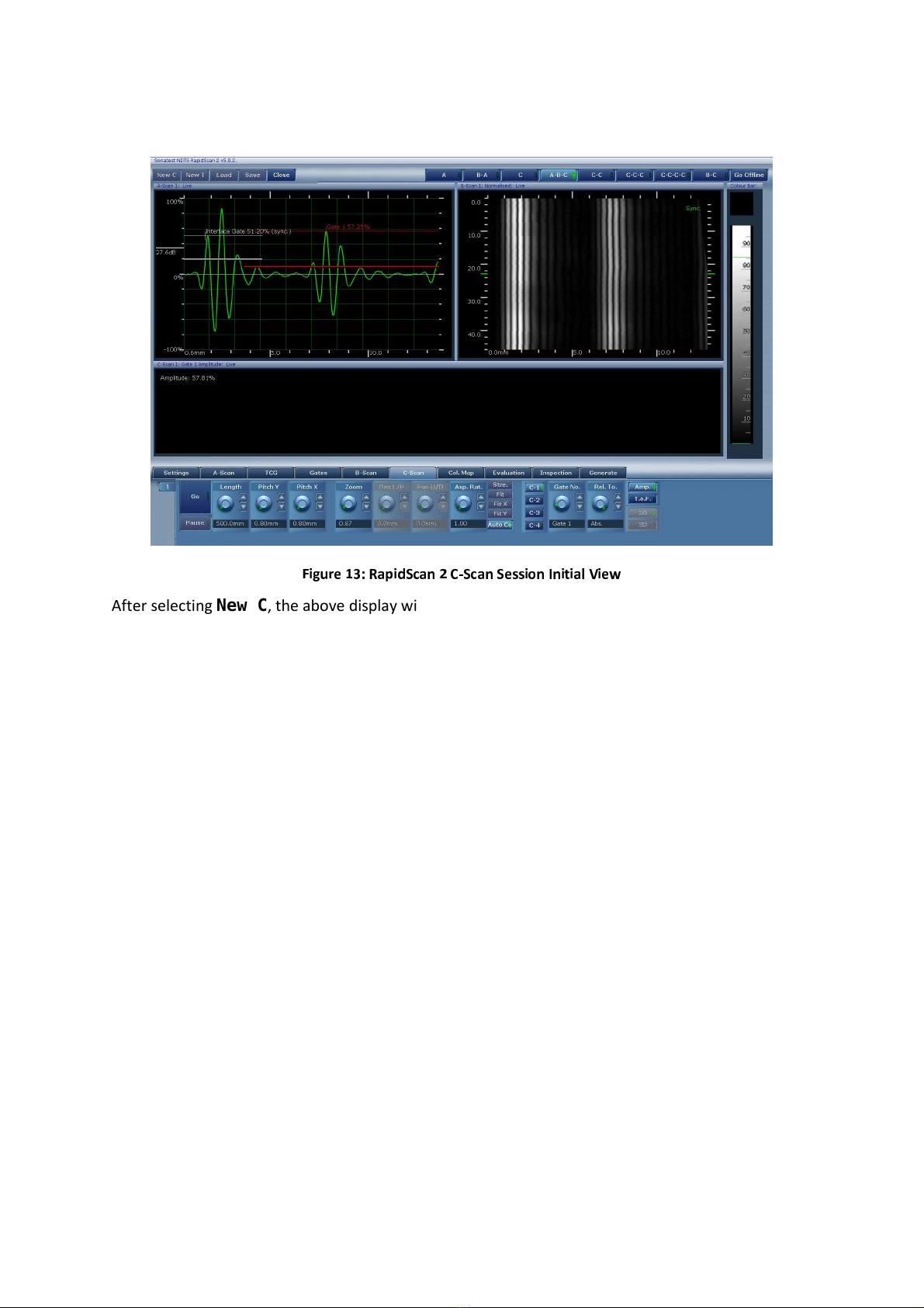
Click on the New C button to start a new C-scan session.
9
After selecting New C, the above display will appear.

10
Using Predefined Instrument Settings
The RapidScan software includes some pre-defined instrument settings for various tools, including
the wheel probe. These can be easily recalled using the Inspection menu, and then either used
directly or altered for the current scan requirements.
To configure the RapidScan instrument with the predefined inspection settings for the wheel probe,
select the Inspection menu. See Figure 14.
Select stripe under the Part control and wheel under the Tool control. Select the Import
button. The RapidScan system is now ready to scan, continue to the Performing a C Scan section on
page 17.
Alternatively, a custom inspection can be set up using the following Configuring the Ultrasonic
Settings section.

11
Configuring the Ultrasonic Settings
Select the Generate menu, see Figure 15.
Ensure Device is set to encoder, Shape is set the stripe, Tool is set to wheel. Enter a name
for the inspection in the Name box. Hit the Create button.

12
Probe and Scan Setup
The settings for the probe and ultrasonic hardware now need to be initialised.
Array Settings
Select the Settings menu, then choose sub-menu two by clicking on the number 2 below and to
the left, see Figure 16.
Press the wheel-probe onto the part firmly as it would be held during scanning. Adjust the P.Zero
(probe zero) control so that the interface echo is entirely within the A-scan and begins
approximately 1mm from the start of the trace, see Figure 16.
P.Zero should be approximately:
Wheelprobe: 25mm
Sliding array or miniature bubbler: 10mm
Adjust C.Freq. (probe array frequency) to match the probe (typically 2.25 Hz , 5 Hz, 11.5 Hz.)

13
Material Settings
Select the A-Scan menu, see Figure 17.
Set the Gain dial so that the interface echo is approximately 80% of FSH (full-screen height.)
Set Mat.Vel. (material velocity) to match component; typically 2900m/s for composite, 5920 for
steel.
Set Range to component thickness plus 30-50% (e.g. 11-12mm for an 8 mm sample)
Set PRF to 10khz for samples under 5-10mm, 5kHz for anything thicker.
The A-scan shown in Figure 17 demonstrates RapidScan 2 configured with these settings.

14
Time-Corrected Gain Settings
If the amplitude of the backwall echo is significantly lower than the interface, then TCG may be
applied to increase the gain according to depth into the sample.
Select the TCG menu, see Figure 18.
Select the Log. and Interface buttons.
Adjust the Gradient dial until the backwall echo is a similar height to the interface echo as in
Figure 18.

15
Gate Settings
Select the Gates menu.
Interface Gate
Select the Interf. gate on the Gate control (white gate.) See Figure 19.
Check that Active, Lock Vel. and Auto Regate buttons are activated.
Set Start, Width and Threshold dial controls so that the interface gate covers the entire
interface echo cleanly (above low level artefacts.)
The mouse can also be used to position the gate; drag the beginning of the gate drawn on the A-scan
left or right to set the Start, drag the end left or right to set the Width and drag the middle up or
down to set the Threshold.
Measurement Gate
Select Gate 1 (red gate) using the mouse or dial control.
Set Trig-by dial to Interf.
Set Start to beyond the end of the interface echo. The interface and gate 1 are allowed to overlap.
Set Width long enough to break backwall echo and extend beyond almost to the length of the A-
scan.
Set Threshold to about 5% FSH (full-screen height.) See Figure 19.

16
Setting the View Layout
Select the C-C-C view on the top of the screen to view multiple C-scans during scanning or select
A-B-C view to see a single C-scan as well as the A and B-scans during scanning.
Select the C-Scan menu., see Figure 20.
Select C-1, and set Gate No. to Gate 1, select Amp. and set Rel. To to Abs.
Select C-2, and set Gate No. to Gate 1, select ToF. and set Rel. To to Interface.
Select C-3, and set Gate No. to Interface, select Amp. and set Rel. To to Abs.

17
Performing a C Scan
Ensure that the area of the sample to be scanned has a thin film of water applied using the water
spray bottle provided.
Recording and valuating Scan Data
Hit the Go button and provide firm pressure downwards and forwards to the wheel probe to scan
the sample.
Depending on the view layout and sample chosen, the result of the scan will look similar to Figure 21
or Figure 22.

18
Select A-B-C view and drag the mouse cursor on the C-scan using the right button to evaluation A-
scans and B-scans at different positions on the sample.

19
Setting up the Scan Colour-Map
Select C-2 to view the depth C-scan, note the range of the colour-map may not be configured to
match the depth of the sample.
Click Col-Map menu. Select C-2 and change the Low value to match the data collected, see Figure
23.
Table of contents
Other Sonatest Test Equipment manuals

Sonatest
Sonatest Masterscan D-70 User manual

Sonatest
Sonatest Sitescan 150 User manual

Sonatest
Sonatest Sitescan 250 User manual

Sonatest
Sonatest SOFRANEL WheelProbe 2 User manual

Sonatest
Sonatest Steelgage II User manual

Sonatest
Sonatest Microgage III Series User manual

Sonatest
Sonatest Sitescan D-50 User manual

Sonatest
Sonatest Wave User manual


